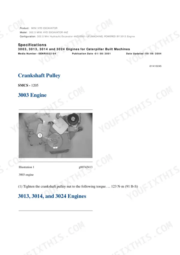
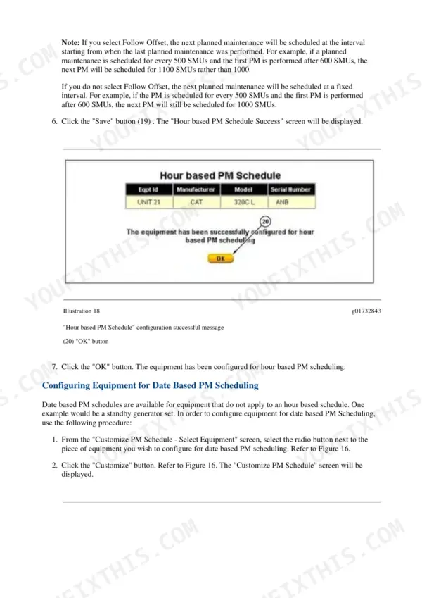
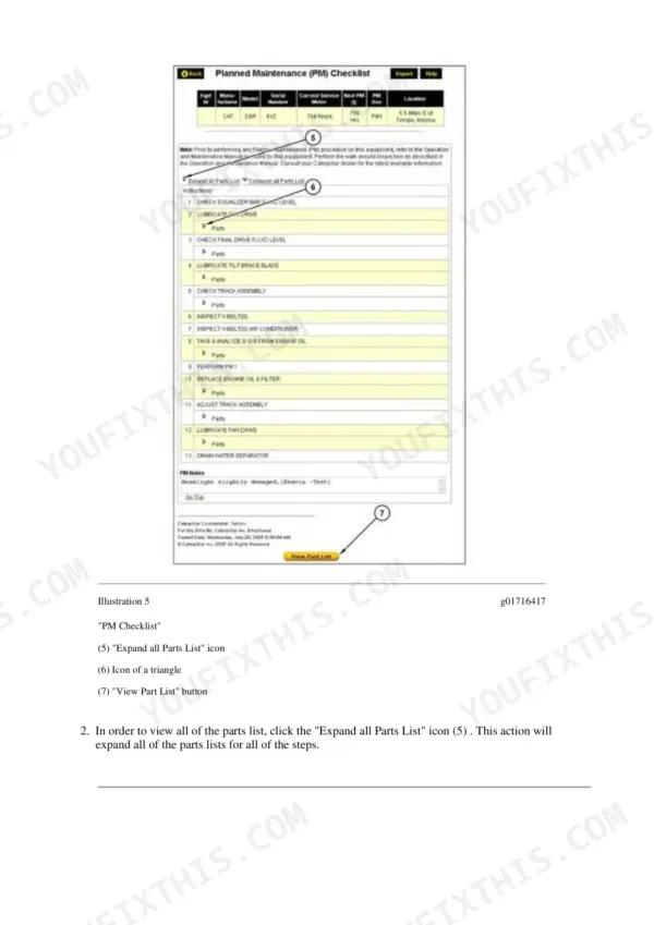
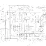
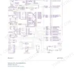
This is the factory repair manual for the 1999-2005 Caterpillar 302.5 mini hydraulic excavator (serial 4AZ00001 and up) with the Cat 3013 diesel. Across 2,386 pages you get teardown and rebuild coverage for the 3013 engine (cylinder head, pistons, crankshaft, timing gears, valve lash), the full hydraulic system with real test specs - main relief at 20600 kPa on the piston pump circuits, 17700 kPa on the gear pump, line relief at 23750 kPa for boom and stick - plus travel motors, swing motor, final drives, undercarriage, and the fuel system. The electrical section runs over a thousand pages of harness tests and schematic sheets, which matters on a machine famous for chafed starter wiring. Metric torque charts close it out.
What's Inside This Repair Manual
| System | Pages | Key Topics |
|---|
| Air Inlet and Exhaust System | 2-31 | Air Cleaner, Turbocharger, Exhaust Manifold, Muffler |
| Basic Engine | 32-306 | Cylinder Head, Pistons, Crankshaft, Timing Gears, Valve Lash |
| Cooling System | 307-376 | Water Pump, Thermostat, Cooling System Test |
| Electrical and Starting System - Component Tests | 377-1035 | Alternator Test, Battery Test, Charging System, Electric Starting Motor, Glow Plugs, Electrical Connector Inspection |
| Electrical and Starting System - Schematics and Specifications | 1036-1415 | System Schematic, Wiring Harness Open and Short Circuit Tests, Electrical Component and Connector Locations, Engine Oil Pressure Switch |
| Engine Arrangement | 1416-1472 | 3013 Engine Arrangement, Engine Specifications |
| Frame and Body | 1473-1493 | Frame, Guards, Covers |
| Fuel System | 1494-1599 | Injection Nozzle Test, Fuel System Pressure, Fuel Shutoff Solenoid |
| Hydraulic System | 1600-1992 | Main Relief Valve, Line Relief Valve, Pilot System Pressure, Piston and Gear Pump, Load Control Valve, Accumulator Charge |
| Implements | 1993-2011 | Boom, Stick, Bucket Linkage |
| Lubrication System | 2012-2041 | Oil Pump, Oil Pressure, Lubrication Routing |
| Operator Station | 2042-2061 | Controls, Pilot Accumulator Charge, Cab |
| Power Train | 2062-2162 | Swing Motor Test, Travel Motors, Final Drives |
| Service Equipment and Supplies | 2163-2179 | Tooling, Fluids, Cleaning Procedures |
| Undercarriage | 2180-2241 | Track Adjuster, Front Idler, Rollers |
| Work Tools | 2242-2250 | Attachments, Work Tool Specifications |
| Torque Specifications | 2251-2295 | Standard Metric Bolt Torque Charts |
| Schematic | 2296-2386 | 302.5 Electrical System Schematic Sheets, Electrical Power Graphic Symbols |
Quick Reference Specifications
| Specification | Value | Page |
|---|
| Gear Pump |
| Relief Valve (Main) Setting (P3) | 17700 ± 500 kPa (2567 ± 73 psi) | p. 1639 |
| Piston Pump |
| Relief Valve (Main) Setting (P1, P2) | 20600 ± 500 kPa (2988 ± 73 psi) | p. 1640 |
| Boom and Stick |
| Relief Valve (Line) Setting (Boom, Stick) | 23750 ± 250 kPa (3445 ± 36 psi) | p. 1641 |
| Bank Valve |
| Pilot and Travel Speed Manifold Relief Valve (1) Pressure | 3900 kPa (565 psi) | p. 1647 |
| Parking Brake, Two Speed Valve, Accumulator, Pilot Valves |
| Pilot and Travel Speed Manifold Relief Valve (2) Pressure | 3400 kPa (490 psi) | p. 1647 |
| Accumulator (4) |
| Accumulator Oil Storage Capacity | 0.5 L (0.53 qt) | p. 1648 |
| Accumulator Charge Pressure | 900 kPa (130 psi) | p. 1648 |
| Accumulator Nitrogen Volume | 30 cc (1.83 in³) | p. 1648 |
| Hydraulic Oil Filter (2) |
| Hydraulic Oil Filter Bypass Pressure | 172 kPa (25 psi) | p. 1654 |