
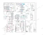
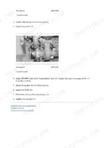
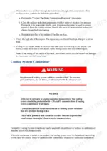
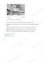
This is the full factory repair library for the Cat 312B and 312B L, not an operator's booklet. It walks the 3054 engine from cylinder head to crankshaft, covers the Stanadyne injection pump with testing and timing adjustment, and gives real numbers - wastegate opens at 88 +/- 4 kPa (12.8 +/- 0.6 psi), exhaust manifold pulls to 44 N.m (33 lb ft). Hydraulics get the deepest coverage: main and pilot valve circuits, travel motor and anti-reaction valves, swing parking-brake solenoid, drift-reduction valves and the blade circuit. Add final drive and swing gear work, track adjuster and idler service, boom/stick/bucket pin replacement, 15 bucket configurations, full torque tables, and foldout hydraulic and electrical schematics for S/N 6SW, 9NW, 9FS and 2KW machines.
What's Inside This Caterpillar 312B, 312B L Repair Manual
| System | Pages | Key Topics |
|---|---|---|
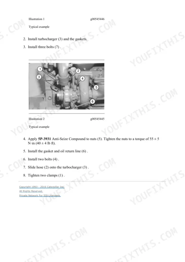
| Air Inlet and Exhaust System | 1-66 | Naturally Aspirated vs. Turbocharged Operation, Turbocharger Components and Function, Wastegate Operation and Testing, Air Cleaner Inspection and Maintenance, Exhaust Temperature Testing |
| Basic Engine | 67-409 | Cylinder Block and Cylinder Head, Crankshaft and Main Bearings, Camshaft and Valve Train, Piston, Ring and Connecting Rod Service |
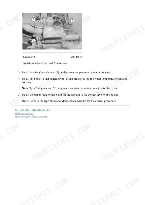
| Cooling System | 410-479 | Radiator and Coolant-Level Test Procedure, Water Temperature Regulator (Thermostat), Fan Drive and Belt Tension, Coolant Specifications |
| Electrical and Starting System - Systems Operation | 480-1090 | VIMS Monitor Panel and Instrument-Panel Operation, EquipmentManager / Product Link Software Setup, Service Meter and Repair-History Logging, Fuel-Use and Idle-Time Reporting, User Checklist and Login Administration |
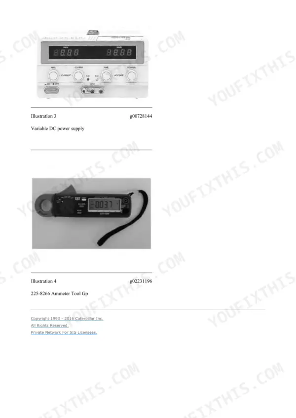
| Electrical and Starting System - Testing and Adjusting | 1091-1391 | Air Inlet Heater Circuit Leak Test, VIMS/ECM Module Presence and Wiring Verification, Digital Multimeter Resistance and Voltage Checks, Monitor Character-Display Diagnostic Entry |
| Electrical and Starting System - Troubleshooting, Specifications & Disassembly | 1392-1664 | Wiring/Connector Fault-Tracing Conventions, Event and Diagnostic Code Handling (Do-Not-Clear Caution), Alternator Charging System High-Idle Test, Connector/Terminal Specifications and Housing Installation |
| Engine Arrangement | 1665-1719 | Engine Design and Configuration Overview, Worn Piston Ring Symptoms, Crankcase Breather Routing, Loose Alternator Belt Diagnosis, General Engine Identification Information |
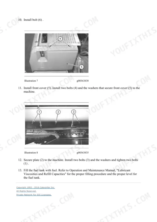
| Frame and Body | 1720-1765 | Counterweight Removal and Installation, Swing Drive Disassembly and Assembly, Upper Structure to Undercarriage Frame Separation, Swing Gear and Bearing Replacement, Fan Guard and Hood Removal |
| Fuel System | 1766-1930 | Stanadyne Fuel Injection Pump Operation, Fuel Return-Line Circuit, Injection Pump Testing and Timing Adjustment, Fuel Filter and Injector Disassembly and Specifications |
| Hydraulic System | 1931-2664 | Main and Pilot Control Valve Circuit Operation, Boom and Stick Drift-Reduction Valves, Swing Parking-Brake Solenoid Valve, Travel Motor and Anti-Reaction Valve Circuits, Blade Circuit and Proportional Reducing Valve |
| Implements | 2665-2724 | Boom Removal, Installation and Bearing/Seal Replacement, Stick (Short/Medium/Long Variant) Removal and Installation, Bucket-Linkage Removal and Bearing/Seal Replacement, Grease-Line Routing for Boom and Stick |
| Lubrication System | 2725-2778 | Engine Oil Pump Inner/Outer Rotor Clearance Measurement, Lubrication Circuit Operation, Oil Pump Disassembly and Specifications |
| Machine Arrangement | 2779-2790 | Scheduled Service-Interval Reference, Heating and Air-Conditioning Service Publication Index |
| Operator Station - Systems Operation | 2791-2971 | HVAC Air-Inlet and Defroster Controls, Automatic Temperature-Control Switch Operation, Cab/Operator-Station System Layout |
| Operator Station - Testing and Adjusting | 2972-3339 | Fuse-Circuit Continuity Test, Air-Conditioning Pressure/Temperature Charge Chart, A/C Refrigerant Recommended Charge Weight, Diagnostic Test Result Checklist |
| Operator Station - Troubleshooting, Specifications & Disassembly | 3340-3638 | A/C Refrigerant Leak Detection and Recovery Procedure, Blower Motor and Evaporator Airflow Troubleshooting, Relief-Valve and Suppressor Wiring Checks, Blower-Wheel Rotation and Damper Positioning Checks |
| Power Train | 3639-3731 | Duo-Cone Conventional Seal Installation, Final Drive Disassembly and Assembly, Final-Drive Sprocket Replacement, Track Roller Service, Track Separation and Connection |
| Service Equipment and Supplies | 3732-3781 | Service Equipment Operation and Testing, Coolant-System Safety Precautions, Disassembly and Assembly of Service Equipment Components |
| Torque Specifications | 3782-3826 | Metric (ISO) and English (SAE) Fastener Torque Tables, Ground Engaging Tool (G.E.T.) Fastener Torque, O-Ring, Flare and Pipe-Thread Fitting Installation Torque, Hose-Clamp Torque Values - Universal Caterpillar/Mitsubishi Chart, Not Machine-Specific |
| Undercarriage | 3827-3892 | Track Adjuster Removal, Disassembly and Assembly, Front Idler and Recoil-Spring Service, Track Carrier-Roller Disassembly and Assembly, Track Roller Disassembly and Assembly |
| Work Tools | 3893-3936 | Multiple Bucket Variant Specifications (15 Configurations), Bucket Pin-Bore and Retaining-Nut Dimensions, Bucket Adjuster and Quick-Coupler Service, Bucket Removal and Installation Procedure |
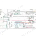
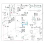
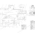
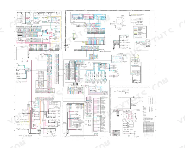
| Schematics (Foldout Diagram Set) | 3937-3973 | 312/312B/312B L Medium-Pressure Hydraulic Schematic (Attachment), Single/Double-Action One-Pump Hydraulic Variants, Stick-Lowering Control Valve Hydraulic Circuit, 312B and 312B L Electrical Wiring Schematic (S/N 6SW, 9NW, 9FS, 2KW), Hydraulic System with Blade Schematic, Fluid Power / Electrical Graphic Symbol Legend |
Quick Reference Specifications
| Specification | Value | Page |
|---|---|---|
| Wastegate opening pressure (2674A081) | 88 +/- 4 kPa (12.8 +/- 0.6 psi) | p. 12 |
| Exhaust manifold tightening torque | 44 N.m (33 lb ft) | p. 23 |
| Muffler nut tightening torque | 30 +/- 7 N.m (22 +/- 5 lb ft) | p. 44 |
| Turbocharger shaft end play (min) | .03 mm (.001 inch) | p. 49 |
| Air inlet heater voltage | 12 volts | p. 50 |
Caterpillar 312B, 312B L Common Problems This Manual Covers
Machine overheats or runs hot under load
Start with the coolant-level check and the water temperature regulator operation described in the Cooling System section — the book explains when the regulator bypasses coolant straight to the water pump inlet and when it opens, which is what you are actually testing. Then verify fan drive and belt tension. On these machines a plugged hydraulic cooler or radiator core chokes airflow long before the regulator is at fault, so clear the cores from the engine side outward before condemning parts.
Manual Section: Cooling System p. 414Travel drive weak, erratic, or one track not pulling
The usual culprits are travel motor case drain leakage or worn seals in the swivel joint passing pressure between circuits — note the manual calls it the swivel joint, so search that term, not centre joint. Frame And Body gives the removal sequence including plugging the hose assemblies against oil loss and pulling the locking bolt; the Hydraulic System section maps the travel motor and anti-reaction valve circuits so you can decide whether the loss sits in the motor or upstream of it.
Manual Section: Frame And Body p. 1746Low power and slow cycle times
Rule out the cheap stuff first. The Air Inlet And Exhaust System section covers air cleaner inspection, turbocharger checks including wastegate opening at 88 +/- 4 kPa and minimum shaft end play of .03 mm (.001 inch), and exhaust temperature testing, all before you dig into hydraulic diagnostics.
Manual Section: Air Inlet And Exhaust System p. 4Engine runs poorly after fuel system repair
The 3054 is unforgiving of injection pump timing and gear alignment mistakes, and the work is split across two sections. Fuel System carries Fuel Injection Pump - Remove and - Install, separated by engine type, plus the return-line circuit and injector specifications. The timing-pin procedure and the timing gear and hub alignment for the Stanadyne and Delphi pumps live in the Basic Engine section — look there rather than in Fuel System, which is where most people waste their first hour.
Manual Section: Fuel System p. 1886Frequently Asked Questions
One side of my 312B travels weak or won't pull straight. Will this manual help me find the cause?
That complaint usually traces to travel motor case drain leakage or worn seals in the swivel joint bleeding pressure between circuits — the book calls it the swivel joint, not a centre joint. Removal, plugging of the hose assemblies and the locking-bolt sequence are laid out in Frame And Body; the travel motor circuits themselves are mapped in the Hydraulic System section so you can isolate whether the loss is in the motor or upstream of it. p. 1746
The engine runs rough or won't start right after the injection pump was off. Is the timing procedure in here?
Yes, and in two places worth knowing apart. The 3054 may carry a Stanadyne or a Delphi injection pump; the timing-pin procedure, timing gear and hub alignment sit in the Basic Engine section, while Fuel System carries Fuel Injection Pump - Remove and - Install split by engine type, plus how the timing advance is energised and retarded in normal running. Pump timing and gear alignment errors are the classic cause of a bad runner after fuel system work. p. 1886
Does it have the cylinder head bolt torque specs and sequence?
Head work lives in the Basic Engine section, which covers cylinder block and head service along with crankshaft, camshaft and piston/rod procedures and their fastener values. The separate Torque Specifications section adds the standard metric and SAE tables plus O-ring, flare and pipe-thread fitting torques. We won't quote head numbers from memory here - use the printed spec and sequence in the book. p. 3782
What does the manual cover on the 312B monitor panel?
The Electrical And Starting System section documents the monitor panel in detail: how the controller talks to it over the data link, the mode keys and what each selection requests, and the character display used for diagnostics. Be aware of one gap rather than discovering it after purchase — this manual does not print a service-indicator reset procedure; it covers monitor operation, service meter units and repair-history logging, not an hour-counter reset. p. 500
Will this match my machine and attachments?
It covers both the 312B and the longer 312B L. The foldout electrical wiring schematic covers serial prefixes 6SW, 9NW, 9FS and 2KW, blade-equipped machines get their own hydraulic schematic, and the Work Tools section carries specifications for 15 bucket configurations plus quick-coupler and bucket adjuster service. p. 1086