
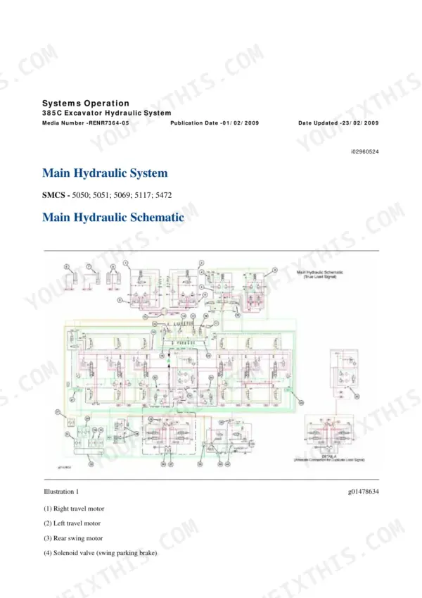
This is the full 7676-page repair book for the Cat 385C L and 385C excavators, delivered as a ZIP with 14 separate full-size schematic PDFs on top - electrical and hydraulic sheets, including the interactive cab/chassis and engine-control schematics you actually need on a laptop next to the machine. It covers the C-18 side and the machine side: testing and adjusting for the hydraulic system with real pressure and flow numbers, Machine ECM diagnostics with Cat ET, disassembly and assembly for swing drive, final drives, injectors and the front linkage. Wear limits come in three tiers - new, rebuild and service limit - so you can decide whether a part goes back in or in the bin.
What's Inside This Caterpillar 385C L, 385C Repair Manual
| System | Pages | Key Topics |
|---|---|---|
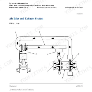
| Air Inlet and Exhaust System | 1-205 | Turbocharger, Aftercooler, Exhaust Manifold, Inlet Manifold Pressure, Excessive Black Smoke, High Air Filter Restriction |
| Basic Engine | 206-925 | Cylinder Head, Pistons and Connecting Rods, Crankshaft Main Bearings, Camshaft Bearings, Rocker Arm and Shaft, Flywheel Housing, Cylinder Liner, Bearing Clearance |
| Cooling System | 926-1135 | Water Pump, Radiator, Water Temperature Regulator, Engine Oil Cooler, Fan Motor Speed, Coolant in Engine Oil |
| Electrical and Starting System: Systems Operation | 1136-2229 | Electronic Control Module (Machine), Sensors, Relays, Solenoid Valve (Proportional Reducing), Modes of Operation, Monitoring System |
| Electrical and Starting System: Testing and Adjusting | 2230-2633 | Wiring Harness (Open Circuit), Wiring Harness (Short Circuit), Electrical Connector, Angle Sensor, Calibration, Connector Contact Description |
| Electrical and Starting System: Troubleshooting | 2634-3325 | Diagnostic Code List, Caterpillar Electronic Technician, CAN Data Link, Electrical Component and Connector Locations, MID 039 Procedures |
| Electrical and Starting System: Specifications, Disassembly and Assembly | 3326-3499 | Alternator and Regulator, Electric Starting Motor, Battery, Coolant Temperature Sensor, Engine Oil Pressure Sensor, Atmospheric Pressure Sensor |
| Engine Arrangement | 3500-3575 | Engine Performance, Engine Cranks But Will Not Start, Engine Misfires, Low Engine Oil Pressure, Engine Overspeed, Poor Acceleration |
| Frame and Body | 3576-3703 | Swing Drive, Swing Gear and Bearing, Counterweight, Upper Frame, Engine Enclosure Group, Swing Bearing Movement |
| Fuel System | 3704-3921 | Electronic Unit Injector, Fuel Transfer Pump, Fuel Filter Base, Water Separator, Fuel Priming Pump, Injector Trim File, Air in Fuel |
| Hydraulic System: Systems Operation, Testing and Adjusting | 3922-4406 | Main Control Valve, Relief Valve (Signal), Relief Valve (Line), Relief Valve (Pilot), Accumulator (Pilot), Swing Pump, Travel Motor, Cylinder Drift, Travel on Level Ground |
| Hydraulic System: Troubleshooting, Specifications, Disassembly and Assembly | 4407-5927 | Swing Motor, Counterbalance Valve (Travel), Swing Cushion Valve, Counterweight Circuit Valves, Piston Motor (Hydraulic Fan), Boom Lines, Auxiliary Hydraulic Lines |
| Implements | 5928-6025 | Boom, Stick, Bucket Linkage, Bearings and Seals, System Pressure |
| Lubrication System | 6026-6124 | Engine Oil Pump, Engine Oil Filter Base, Engine Crankcase Pressure (Blowby), Excessive Engine Oil Consumption, Low Engine Oil Pressure |
| Machine Arrangement | 6125-6141 | Service Intervals, Heating and Air Conditioning Service Publications |
| Operator Station | 6142-7236 | Joystick Control, Hydraulic Lockout Control, Heating and Air Conditioning Unit, Refrigerant Compressor, Evaporator Coil, Blower Motor, Automatic Temperature Control Unit |
| Power Train | 7237-7370 | Final Drive, Sprocket, Track Roller, Duo-Cone Conventional Seals, Pump Drive Coupling |
| Service Equipment and Supplies | 7371-7453 | Required Tools, Hydraulic Tank and Filter, Oil Filter (Return), Fuel Filter Base, Cab Pressurization and Filtration System, Manifold Gauge Set (Refrigerant) |
| Torque Specifications | 7454-7503 | Metric (ISO) Fasteners, English (SAE) Fasteners, Ground Engaging Tool (G.E.T.) Fasteners, Straight Thread O-Ring Fittings, Hose Clamps, Bulkhead Nuts |
| Undercarriage | 7504-7639 | Hydraulic Track Adjusters, Front Idler and Recoil Spring, Track Carrier Roller, Track Roller Frame, Track Roller Mounting |
| Work Tools | 7640-7676 | Bucket, Bucket Adjuster, Combined Function Hydraulic System, One-Way Flow Hydraulic System |
Quick Reference Specifications
| Specification | Value | Page |
|---|---|---|
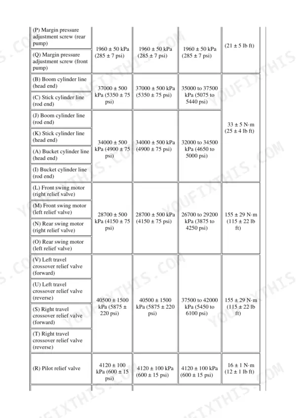
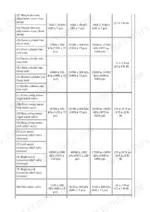
| Signal relief valve - boom, stick, bucket (digging mode) | 32000 ± 500 kPa (4650 ± 75 psi) | p. 4285 |
| Signal relief valve - travel and heavy lift circuits | 35000 ± 500 kPa (5075 ± 75 psi) | p. 4288 |
| Line relief valve - boom cylinder head end | 37000 ± 500 kPa (5350 ± 75 psi) | p. 4295 |
| Line relief valve - bucket cylinder head end | 34000 ± 500 kPa (4900 ± 75 psi) | p. 4296 |
| Swing motor relief valve | 28700 ± 500 kPa (4150 ± 75 psi) | p. 4307 |
| Travel crossover relief valve | 40500 ± 1500 kPa (5875 ± 220 psi) | p. 4401 |
| Pilot relief valve | 4120 ± 100 kPa (600 ± 15 psi) | p. 4266 |
| Margin pressure - front and rear pump | 1960 ± 50 kPa (285 ± 7 psi) | p. 4281 |
| Initial standby pressure | 2000 kPa (290 psi) | p. 4300 |
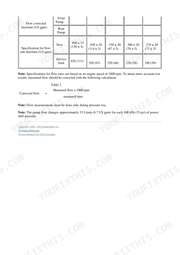
| Front pump flow at 12000 kPa - new | 490 ± 15 L/min (130 ± 4 US gpm) | p. 4369 |
| Front pump flow at 12000 kPa - service limit | 420 L/min (111 US gpm) | p. 4369 |
| Swing pump flow at 5000 kPa - new | 450 ± 15 L/min (119 ± 4 US gpm) | p. 4389 |
| Pilot pump flow - new | 90 ± 5 L/min (23.8 ± 1.3 US gpm) | p. 4395 |
| Pilot pump flow - service limit | 74 L/min (19.5 US gpm) | p. 4395 |
| Swing motor case drain flow - new | 22 L/min (5.8 US gpm) | p. 4307 |
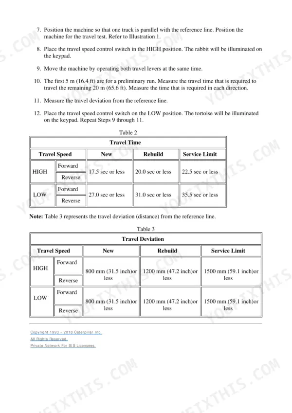
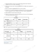
| Travel time, three revolutions High forward - new | 17.5 sec or less | p. 4237 |
| Travel time, three revolutions High forward - service limit | 22.5 sec or less | p. 4237 |
| Machine drift on a 12 degree slope - new | 10 mm (0.39 inch) or less | p. 4244 |
| Machine drift on a 12 degree slope - service limit | 25 mm (0.98 inch) or less | p. 4244 |
| Hydraulic oil temperature for testing | 55 ± 5 °C (131 ± 9 °F) | p. 4312 |
Caterpillar 385C L, 385C Common Problems This Manual Covers
Hard starting, misfire or sudden shutdown from water and dirt in the fuel
The Fuel System section covers the water separator, fuel transfer pump, fuel filter base and priming pump, plus the air-in-fuel test procedure. It also documents electronic unit injector replacement and the injector trim file step that gets skipped and causes rough running afterward.
Manual Section: Fuel System p. 3719Boom or stick drifts down under load, or the whole machine creeps on a slope
Testing and Adjusting gives the cylinder drift procedure with hard numbers: 10 mm or less on a 12 degree slope when new, 25 mm as the service limit. It then points you at line relief valves - boom head end is set at 37000 ± 500 kPa - and the control valve checks that separate seal leakage from valve problems.
Manual Section: Hydraulic System - Systems Operation, Testing and Adjusting p. 4244Machine pulls to one side, travels slow, or the tracks are loose and noisy
The Undercarriage section covers hydraulic track adjusters, front idler and recoil spring service, and track roller mounting. Pair it with the travel tests in Testing and Adjusting: three revolutions in high forward should take 17.5 seconds or less new, 22.5 at the service limit, which tells you whether a travel motor is actually down on power.
Manual Section: Undercarriage p. 4237Warning lights, dead gauges or intermittent electrical faults that come and go with vibration
The Electrical and Starting System troubleshooting section pairs the diagnostic code list with connector location drawings, then the testing procedures show how to prove an open or short in a harness with a meter. Most intermittent faults on these machines end at a corroded connector contact, and the connector inspection procedure is written for exactly that.
Manual Section: Electrical and Starting System - Troubleshooting p. 2634Frequently Asked Questions
What are the hydraulic pressure settings for the 385C L, and does the manual show how to check them?
Yes, with tolerances. Signal relief for boom, stick and bucket in digging mode is 32000 ± 500 kPa (4650 ± 75 psi), travel and heavy lift circuits run 35000 ± 500 kPa (5075 ± 75 psi), and pilot relief is 4120 ± 100 kPa (600 ± 15 psi). The Testing and Adjusting section walks through gauge hookup points and tells you to test at 55 ± 5 °C oil temperature - checking pressures on cold oil is how people end up chasing ghosts. p. 4285
Can I read and clear diagnostic codes on this machine, or do I need a dealer?
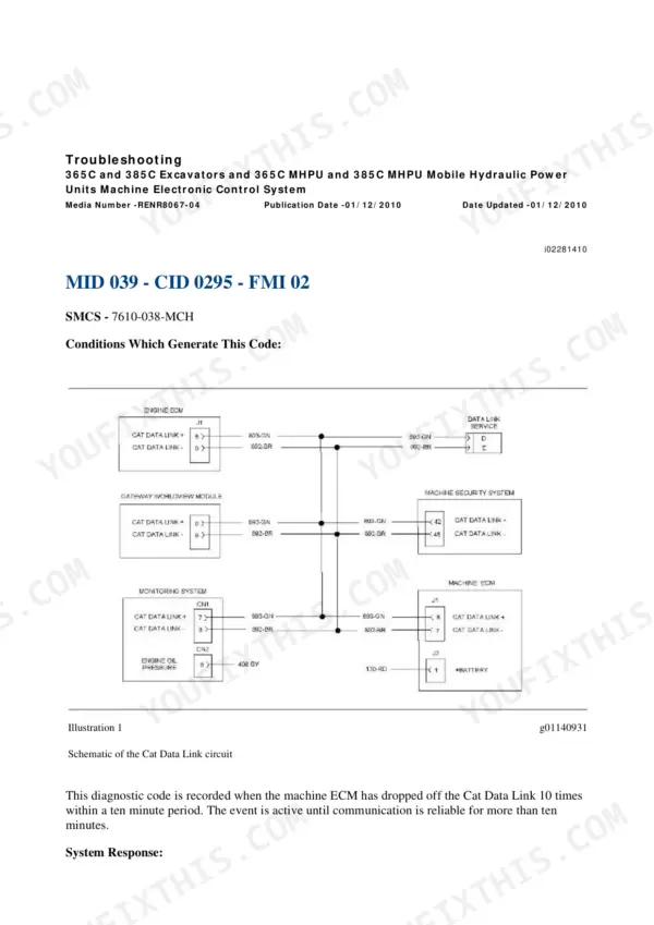
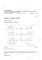
The 385C has a Machine ECM (MID 039) and the manual covers the full electronic side: the diagnostic code list, Cat Electronic Technician hookup, the CAN data link, and component and connector location drawings so you can find the module or sensor a code points at. You still need Cat ET software and an adapter for full work, but the troubleshooting section also gives wiring harness open-circuit and short-circuit test procedures you can run with a multimeter. p. 1173
Are torque specs included for things like track shoe bolts and swing bearing bolts?
There is a dedicated Torque Specifications section covering metric ISO and SAE fasteners, ground engaging tool fasteners, straight thread O-ring fittings, hose clamps and bulkhead nuts. Component-specific torques sit in the disassembly and assembly procedures - swing gear and bearing under Frame and Body, track roller mounting and track shoes under Undercarriage. The fastener charts give the range by thread size, so a bolt without a callout in its own procedure still has a number. p. 7459
The machine feels weak and slow when hot. Will this manual help me figure out if it is the pumps?
That is exactly what the pump flow tests are for. Front pump should move 490 ± 15 L/min at 12000 kPa when new, with a service limit of 420 L/min - below that, the pump is telling you something. Same style of numbers for the swing pump (450 ± 15 L/min at 5000 kPa) and pilot pump (90 new / 74 service limit). The procedures give the test rig setup, so you measure instead of swapping parts on a hunch. p. 4369
What exactly do I get in the download?
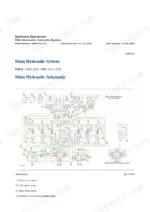
One ZIP file: the 7676-page repair manual covering systems operation, testing and adjusting, troubleshooting, specifications and disassembly and assembly for every system from the turbocharger to the bucket linkage, plus 14 separate full-size schematic PDFs for the electrical and hydraulic systems. The schematics being separate files matters - you can print a hydraulic sheet at full size or keep it open on a second screen while you trace a circuit. p. 1


Reviews
There are no reviews yet.