


Built around the Cnh Industrial F5 engine family, this 393-page service manual (OEM #47730922) covers F5BFL413, F5DFL463, F5GFL413, and F5HFL463 variants in factory-spec detail. Packed with torque tables, exploded assembly views, and a full crankcase specification section, it gives you piston ring end gap tolerances (0.20–0.35 mm on the top ring) alongside complete tightening sequences for every critical fastener. Electrical system overviews and block diagrams illustrate the entire electrical side: fuel injection, engine cooling, oil system, intake and exhaust, engine control, and starting circuits. Stage your high-pressure fuel line fittings at 20–30 N·m, then rotate an additional 90°; torque turbocharger mounting nuts to 28 N·m. No more guessing whether that forum spec applies to your variant. One download and your phone becomes your shop reference: bookmark to any section, search any spec by keyword.
What's Inside This CNH Industrial F5 Tier 4B Manual
| System | Pages | Key Topics |
|---|---|---|
| Introduction | 7-18 | Foreword - Important Notice Regarding Equipment Servicing, Safety Rules, Safety Rules - Ecology and the Environment, Basic Instructions - Shop and Assembly |
| Engine | 19-284 | Engine and Crankcase |
| Electrical Systems | 285-389 | Fuel Injection System, Engine Cooling System, Engine Oil System, Engine Intake and Exhaust System, Engine Control System, Engine Starting System |
Quick Reference Specifications
| Specification | Value | Page |
|---|---|---|
| Turbocharger mounting nuts torque | 28 N·m (21 lb ft) | p. 180 |
| Oil supply line banjo bolt torque | 35 N·m (26 lb ft) | p. 180 |
| High pressure fuel line fittings torque (Stage 1) | 20 - 30 N·m (15 - 22 lb ft) | p. 166 |
| High pressure fuel line fittings torque (Stage 2) | Turn additional 90 ° | p. 166 |
| Piston ring end gap - Top | 0.20 - 0.35 mm (0.0079 - 0.0138 in) | p. 23 |
| Piston ring end gap - Middle | 0.60 - 0.80 mm (0.0236 - 0.0315 in) | p. 23 |
| EGR cooler mounting bolts and nuts torque | 20 - 30 N·m (15 - 22 lb ft) | p. 279 |
| EGR flex pipe torque | 25 N·m (18 lb ft) | p. 279 |
| Engine coolant temperature sensor resistance at -20 °C (-4 °F) | 10.5 kOhm | p. 294 |
| Exhaust manifold temperature sensor resistance at 25 °C (77 °F) (Straight sensor) | 219.6 Ω | p. 313 |
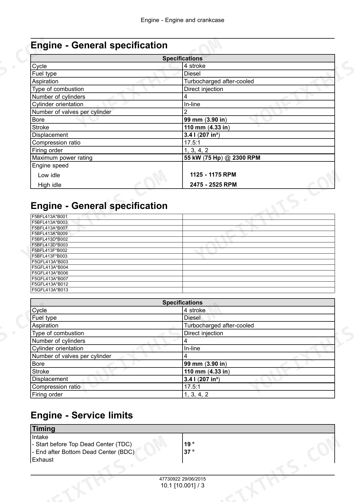
| Engine Displacement | 3.4 l (207 in³) | p. 22 |
| Engine Firing Order | 1, 3, 4, 2 | p. 22 |
CNH Industrial F5 Tier 4B Common Problems This Manual Covers
CNH Industrial F5DFL463 engine milky or foamy oil on dipstick, coolant disappearing without external leaks
Check the dipstick and oil filler cap for gray foam or chocolate-colored residue. Inspect piston rings after pulling the cylinder head; top ring end gap spec is 0.20 - 0.35 mm (0.0079 - 0.0138 in) per page 23. If gap is out of spec or cylinder bore exceeds 99.020 mm (3.8984 in), plan for full overhaul.
Manual Section: Engine lubrication system - Troubleshooting p. 23Sudden power loss and excessive black smoke under load, no active fault codes stored
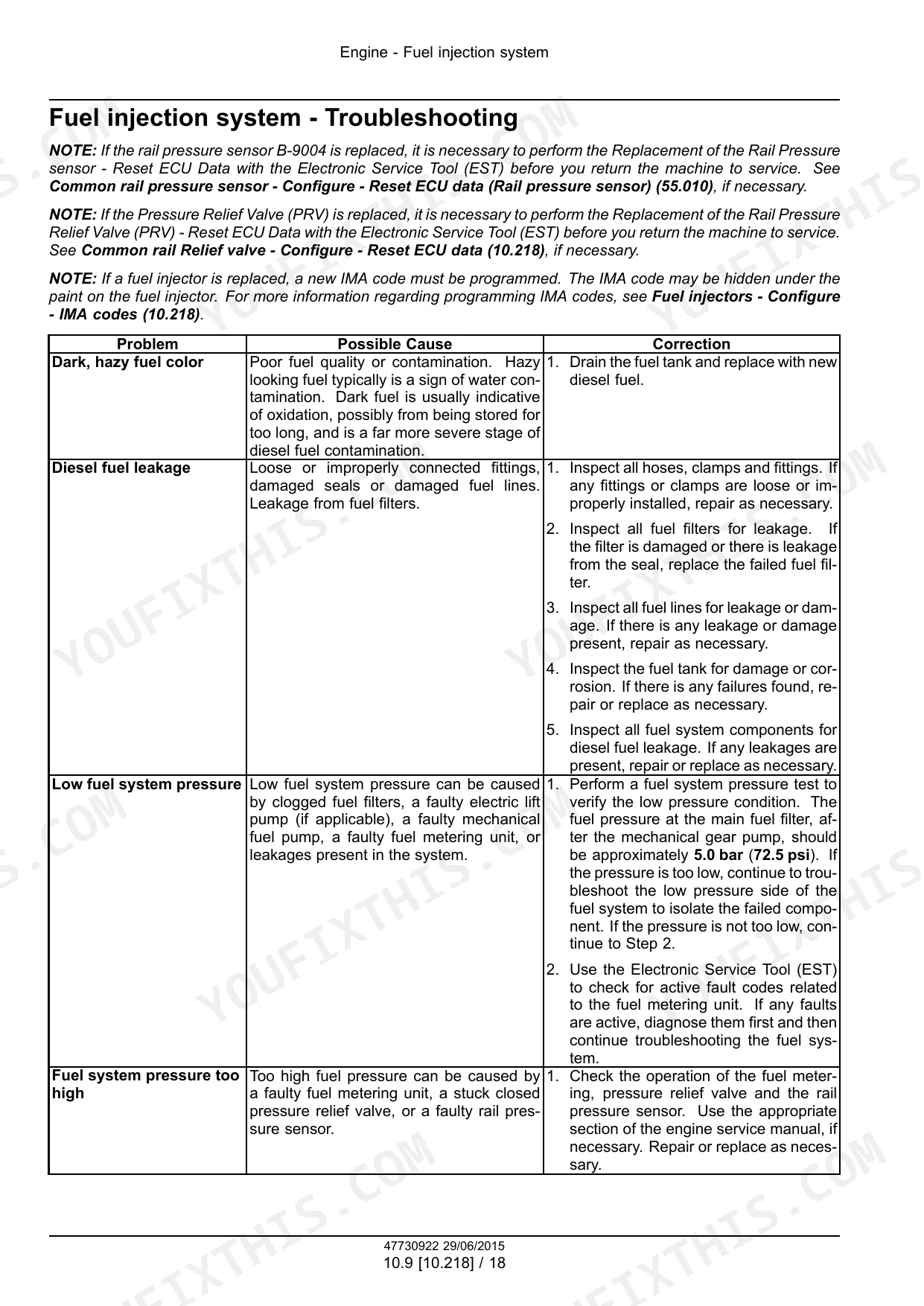
Verify fuel filter condition and check for restrictions in the supply line. Review fuel injection troubleshooting starting and measure common rail pressure. If low, inspect injectors for fouling and leaks. Reinstall high-pressure fuel line fittings in two stages: 20 - 30 N·m (15 - 22 lb ft) Stage 1, then an additional 90°.
Manual Section: Fuel injection system - TroubleshootingTurbocharger whining or grinding noise, blue-gray smoke from exhaust, oil consumption up
Inspect the oil supply line to the turbocharger for blockage and check shaft radial play by hand; excessive movement confirms bearing failure. Remove the unit and torque mounting nuts to 28 N·m (21 lb ft) on reinstall per page 180. Test wastegate modulator valve Y-9008 resistance; spec is 21.8 - 24.2 Ω per page 183.
Manual Section: Turbocharger - Troubleshooting p. 180Engine overheating with error code 146 active, coolant temperature high, excessive white smoke from tailpipe
Verify coolant level and pressure-test the system for external leaks before pulling sensors. Measure coolant temperature sensor resistance; at -20 °C (-4 °F) it should read 10.5 kOhm per page 294. If the sensor checks out, inspect the thermostat for sticking and flush the cooling passages for scale or debris blocking flow.
Manual Section: Engine cooling system - Troubleshooting p. 294Low oil pressure warning at idle, oil level correct, no visible external leaks
Check oil pressure with a mechanical gauge at the main gallery. Minimum pressure at 500 RPM is 0.6 - 0.9 bar (8.7 - 13.0 psi); at 2500 RPM expect 2.9 - 4.0 bar (42.0 - 58.0 psi) per page 205. If pressure reads low with correct oil viscosity and level, pull the pump and inspect the relief valve for debris.
Manual Section: Engine lubrication system - Troubleshooting p. 205Hard starting in cold weather, glow plug light cycling but engine cranks slowly without firing
Test each glow plug with a current probe; a dead plug draws zero current and needs replacement. Torque new plugs to 8 - 10 N·m (71 - 89 lb in) per page 340. Also check crankshaft sensor resistance, spec is approximately 900 Ω per page 326, since a weak signal can mimic cold-start symptoms.
Manual Section: Electrical Systems - 55 p. 340Frequently Asked Questions
What are the recommended service intervals?
The manual does not explicitly list a comprehensive table of recommended service intervals. However, specific procedures mention intervals for certain actions, such as allowing the starter to cool for 30 seconds after cranking for 20 seconds (page 161) or installing the flywheel housing within 10 minutes of sealant application (page 91). p. 161
What fluids and capacities does this machine require?
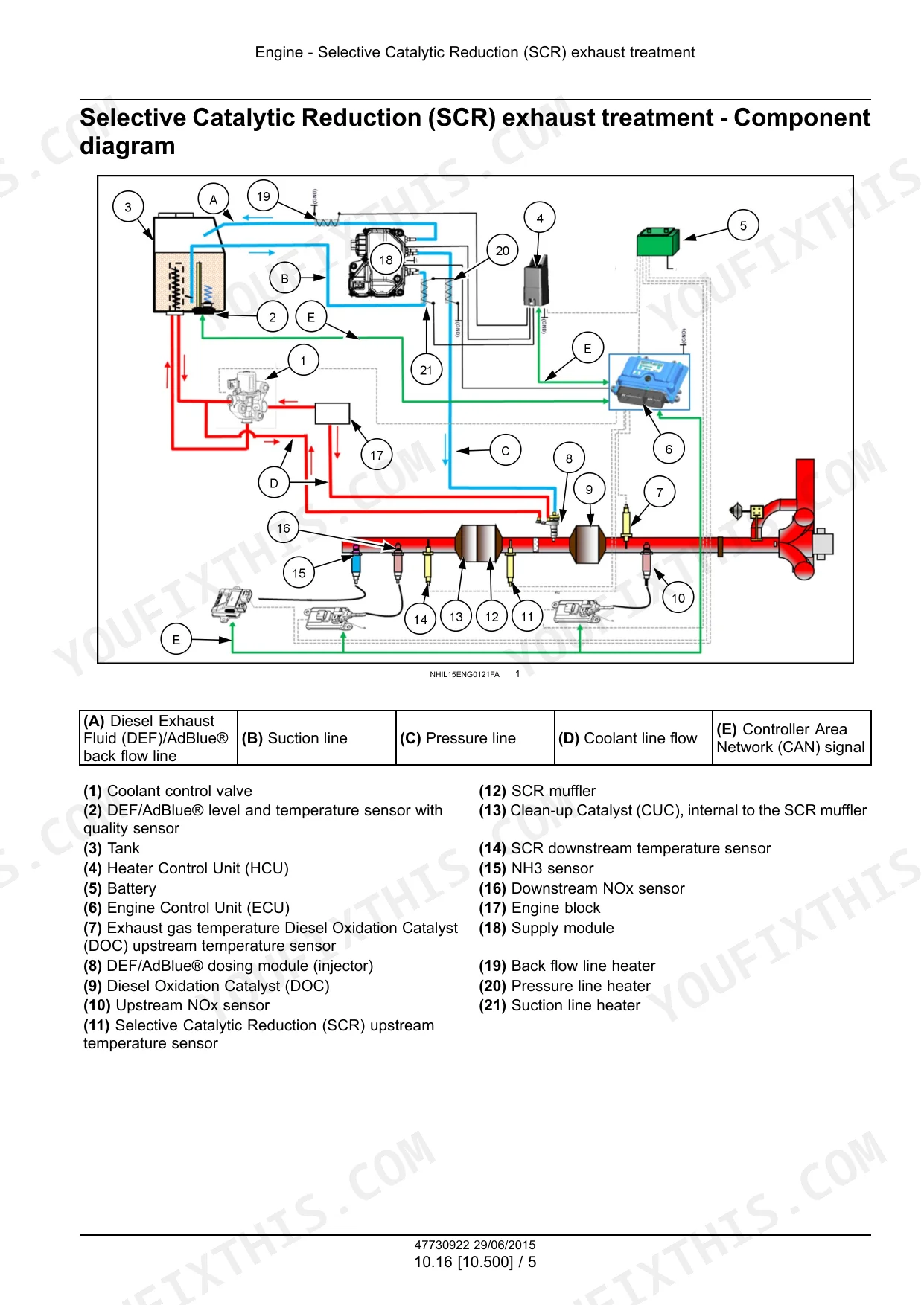
The engine uses Diesel fuel and has a displacement of 3.4 liters (207 in³). For the Diesel Exhaust Fluid (DEF)/AdBlue® dosing module, the 12 V system requires 3700 mA at 14 V battery voltage, and the 24 V system requires 2750 mA at 28 V battery voltage. The DEF/AdBlue® fluid freezes at -11 °C (12 °F). p. 22
How to troubleshoot engine won't start?
If the engine does not start, especially if it's due to air in the fuel system, you should bleed the fuel system. For machines with a primer button, remove the fuel bleed screw (1) from the filter housing, press the primer button, and reinstall the screw when fuel is present. For machines without a primer button, turn the key to ON for 30 seconds, then OFF, loosen the bleed screw (1) on the filter base to purge air, tighten it, and crank the engine for 20 seconds at a time, allowing 30 seconds for the starter to cool. p. 161
What are the hydraulic system specifications?
The manual mentions hydraulic fluid in safety rules but does not provide specific hydraulic system specifications such as pressure, flow rates, or capacities. p. 10
Is this Service Manual a digital download?
This is a 393-page searchable PDF ready for immediate download. Works on any device, so pull it up on your phone while you're under the hood. No shipping, no waiting.
Is this Cnh Industrial F5 Series Service Manual printable?
The PDF is DRM-free. Print whatever sections you need to take out to the shop. Standard letter or A4 paper works.
Can I find wiring schematics in this Cnh Industrial F5 Series manual?
Yes, full electrical schematics are included with wire colors, connector locations, and circuit descriptions.


Reviews
There are no reviews yet.