
This 280-page Ford 5640, 6640, 7740, 7840, 8240, 8340 Shop Manual is the Ford 7740 shop manual pdf you pull up when the tractor won't start and forum posts aren't cutting it. Inside you get full electrical wiring diagrams with harness routing and connector pinouts, hydraulic schematics covering both closed-center load sensing and open-center systems, and a dedicated troubleshooting section for charge pressure faults and warning lights. You also get exploded views for engine teardown and a torque table you can trust. Reset the service interval to 0300 hours through the dash function switches, and check oil sump capacity before you ever crack a bolt. Stop chasing wiring faults with a test light and a hunch. This searchable PDF carries bookmarks for every system, so you jump straight from cab electrical to rear axle without hunting through 280 pages by hand.
Complete the set for your 5640–8340
- Operator Manual: Ford 5640, 6640, 7740, 7840 S Range Operator Manual
Other edition of this manual
What's Inside This Ford 5640–8340 Manual
| System | Pages | Key Topics |
|---|---|---|
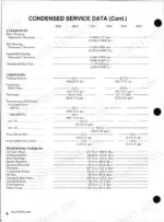
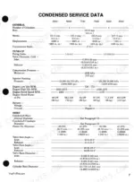
| Information & Instructions | - | How to Use the Index, Specifications, Procedural Data, Index, Table of Condensed Service Specifications, Procedures Paragraphs |
| Dual Dimensions | - | U.S. Customary Systems of Measurement, Metric (Si) Systems of Measurement, First Specification, Second Specification, Converted Measurement |
| Brakes | - | Adjustment, Brake Discs and Actuating Assembly, Master Cylinder, System Bleeding |
| Clutch, Engine | - | Clutch Assembly, R&R, Clutch Linkage, Clutch Master Cylinder, Clutch Release Bearing, Tractor Split |
| Cooling System | - | - |
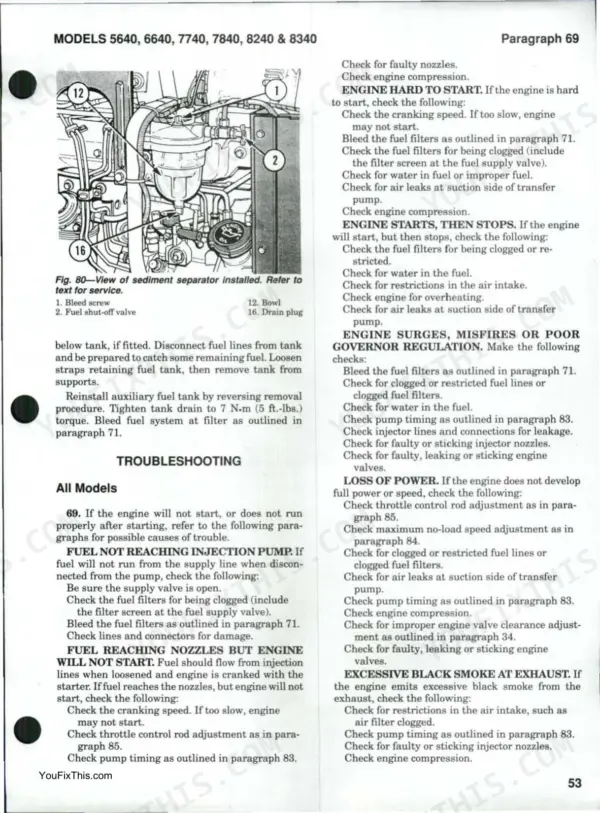
| Diesel Fuel System | - | - |
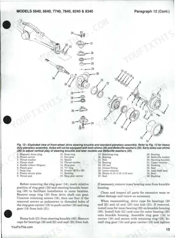
| Differential, Main Drive Bevelgears, Final Drive & Rear Axles | - | Split Between Transmission and Rear Axle Center Housing, Differential and Differential Lock, Differential Bearing Preload, Bevel Pinion, Rear Axle and Final Drive |
| Dual Power (16 X 4 Transmission) | - | - |
| Electrical System | - | - |
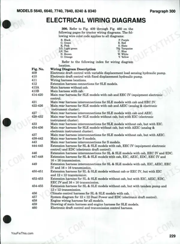
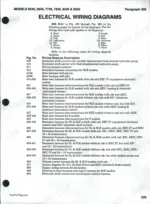
| Electrical Wiring Diagrams | - | Wire Color Code, Wiring Diagram Description, Wiring Harness Locations, Extension Harness Connections, Main Harness, Main Rear Harness |
| Engine & Components | - | Engine, R&R, Cylinder Head, Rocker Arms, Valve Clearance, Timing Gears, Crankshaft Oil Seals |
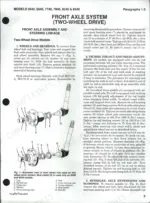
| Front Axle (Two-Wheel Drive) | - | Axle Center Member, Pivot Pins and Bushings, Front Support, Spindles, Axle Extentions and Bushings, Tie Rod, Toe-Out and Tread Adjustment, Wheels and Bearings |
| Clutch Assembly, R&R | - | Remove and Overhaul, Clutch Disc, Pressure Plate, Diaphragm Type Pressure Plate |
| Clutch Linkage | - | Mechanically Actuated Clutch Linkage Adjustment, Hydraulically Actuated Clutch Linkage Adjustment, Clutch Pedal Free Travel, Cable Operated Interlock Mechanism |
| Clutch Master Cylinder | - | Models with Hydraulically Actuated Clutch Linkage, R&R and Overhaul, Bleeding System |
| Clutch Release Bearing | - | Models with Mechanically Actuated Clutch Linkage, Models with Hydraulically Actuated Clutch Linkage, R&R and Overhaul |
| Tractor Split | - | All Models Except 16 × 16 Transmission, Separation Procedure, Reassembly Procedure |
| Radiator | - | All Models, Remove and Reinstall, Installation Procedure |
| Radiator Pressure Cap and Thermostat | - | All Models, Radiator Pressure Cap, Thermostat Location, Thermostat Removal, Thermostat Opening Temperature, Outlet Housing Retaining Screws Torque |
| Water Pump | - | - |
| Adjustments | - | - |
| Filters and Bleeding | - | - |
| Fuel Injection Pump | - | Remove and Reinstall, Pump Timing, Engine Speed, Governor Control Linkage |
| Fuel Injectors | - | Locating a Faulty Injector, Injector Testing, Remove and Reinstall, Overhaul |
| Fuel Tanks | - | - |
| Control Valve | - | Operation, Solenoid, Pilot Valve, Valve Spool, R&R, Overhaul |
| Dual Power Unit | - | Remove and Reinstall, Overhaul Dual Power, Planetary Gear Set End Play |
| Lubrication | - | Transmission Lubricant Capacity, Oil Level, Recommended Lubricant, Drain and Replace, Hydraulic Oil Filter |
| Pressure Test | - | Dual Power Clutch Pressure, Lubrication Circuit Pressure Relief Valve, Dual Power System Oil Pressure |
| Troubleshooting | - | No Power to Rear Wheels (Direct Drive), No Power to Rear Wheels (Underdrive), Engine Stalls or Lugs (Direct Drive to Underdrive), Engine Stalls or Lugs (Underdrive to Direct Drive) |
| Alternator and Regulator | - | Operating Tests, Battery Temperature Sensor, Charging Current and Voltage, R&R and Overhaul, Component Tests |
| Instrumentation | - | Models with Analog or Analog/Electronic Instrument Cluster, Warning Lights, Main Display, Touch-Sensitive Function Switches, Battery Voltage, Dash Connectors |
| Starting Motor | - | Operating Tests, R&R and Overhaul, Brush Minimum Length, Armature Shaft End Play, No-Load Test |
| Cam Followers | - | Removal, Specifications, Clearance |
| Camshaft and Bearings | - | Removal, End Play, Backlash, Bushings, Journals, Installation |
| Connecting Rods and Bearings | - | Big End Bearings, Piston Pin Bushings, Rod Twist and Bend, Crankpin Specifications, Bearing Liner Clearance, Side Float |
| Connecting Rod and Piston Units | - | Removal, Identification Marks, Piston Pin Snap Ring, Bearing Liner Alignment, Connecting Rod Bolts, Tightening Torque |
| Crankshaft and Main Bearings | - | Main Bearing Support, End Thrust, Removal, Bearing Liners, Main Journal Diameter, End Play |
| Crankshaft Oil Seals | - | Front Oil Seal Removal, Front Oil Seal Installation, Rear Oil Seal Removal, Rear Oil Seal Installation, Rear Oil Seal Run-Out Check, Rear Oil Seal Cover Installation |
| Cylinder Head | - | Remove and Reinstall, Rocker Arms, Valve Clearance, Valves, Stem Seals and Seats, Valve Guides and Springs |
| Engine Balancer (5640, 6640, 7740) | - | Balancer Removal, Balancer Gear Backlash, Balancer Reassembly, Balancer Lubrication Port, Balancer Gear Timing Marks |
| Engine, R&R | - | Electrical Component Disconnection, Fuel System Component Disconnection, Cooling System Component Disconnection, Hydraulic System Component Disconnection |
| Exhaust Valve Rotators | - | - |
| Flywheel | - | Flywheel Removal, Clutch Removal, Flywheel Installation, Flywheel Retaining Screws Torque, Starter Ring Gear Installation |
| Oil Pump and Relief Valve | - | Oil Pump Removal, Oil Pump Overhaul, Oil Pump Backlash, Relief Valve Test, Relief Valve Adjustment, Relief Valve Spring Pressure |
| Oil Sump | - | Sump Removal, Oil Drainage, Component Disconnection, Sump Retaining Screws, Sump Reinstallation |
| Pistons and Rings | - | - |
| Hydraulic Lift (Electronic Draft Control) | - | Operation, Error Code Recovery, Hydraulic Lift Autocalibration Procedure, Fault Diagnostic Chart, Hydraulic Lift Cover, Electronic Draft Control Valve |
| Hydraulic Lift (Top Link Sensing) | - | External Linkage Adjustment, Hydraulic Lift Cover and Cylinder, Internal Linkage Adjustment, Lift Assist Cylinder, Operation, Priority Valve Pack |
| Hydraulic System | - | - |
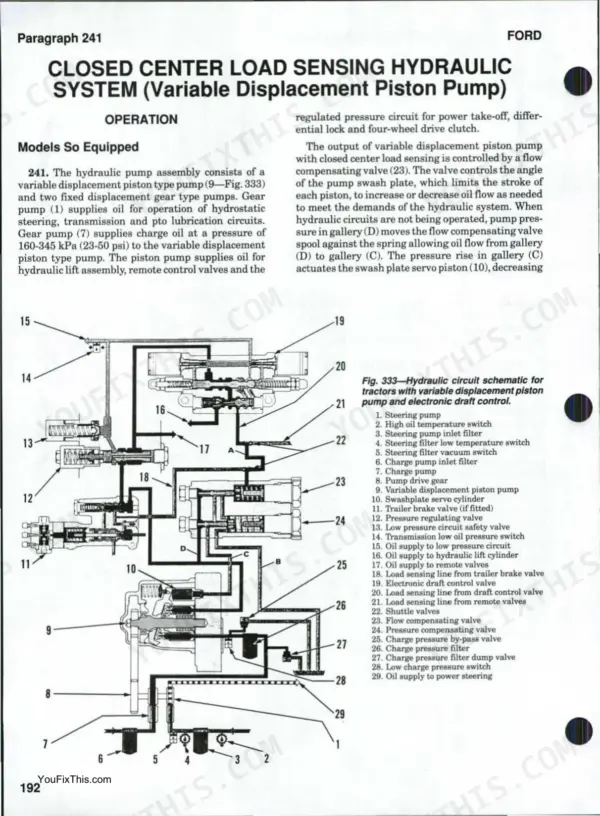
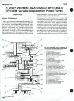
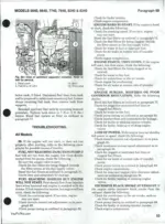
| Hydraulic System (Closed Center Load Sensing) | - | Operation, Pressure Testing, Pump Overhaul, Troubleshooting |
| Hydraulic System (Open Center ) | - | Engine Mounted Auxiliary Gear Pump, Operation, Pressure Testing, Transmission Mounted Tandem Gear Pump |
| Hydrostatic Steering | - | Fluid and Bleeding, Power Cylinder, Pump, Steering Valve, Tests and Adjustment, Troubleshooting |
| Power Take-Off | - | Operating Principles, PTO Clutch and Control Valve (Mechanically Operated), PTO Clutch and Control Valve (Electric Solenoid Operated), PTO Output Shafts and Gears |
| Reduction Gearbox | - | - |
| Remote Control Valves | - | Adjustments, Remote Control Valve, Remote Valve Couplers |
| Transmission (8 X 2 Constant Mesh ) | - | Lubrication, Remove and Reinstall, Shift Cover, Shift Rails and Forks, Mainshaft, Main Countershaft |
| Transmission (16 X 16 Power Shift Built Prior to September 1993) | - | Clutch Calibration, Electrical Component Description, Gearshift Cover, Gearshift Linkage, Pressure Testing, Transmission Control Valve |
| Transmission (16 X 16 'Quad Mod' Power·shift Built September 1993 and After) | - | Clutch Fill Time Calibration, Clutch Spring Pressure Calibration, Gear Shift Control Cables, Pressure Testing, Transmission Control Valve, Transmission Overhaul |
| Transmission (12 X 12 Synchro-Shift) | - | Lubrication, Remove and Reinstall, Shift Covers, Top Cover, Gear Shift Linkage, Front-Wheel Drive Output Assembly |
| Transmission (12 X 12 Synchro·Shift with Dual Power ) | - | Clutch Calibration, Dual Power Unit, Electro-Hydraulic System, Lubrication Control Valve, Pressure Testing, Transmission Control Valve |
Quick Reference Specifications
| Specification | Value | Page |
|---|---|---|
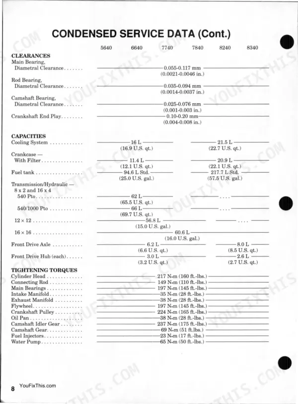
| Oil Sump | 58 | p. 5 |
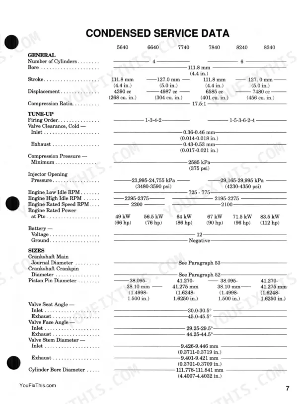
| Number of Cylinders | 4 (5640, 6640, 7740), 6 (7840, 8240, 8340) | p. 7 |
| Compression Ratio | 17.5:1 | p. 7 |
| Valve Clearance, Cold - Inlet | 0.36-0.46 mm | p. 7 |
| Cooling System Capacity | 16 L (5640, 6640, 7740), 21.5 L (7840, 8240, 8340) | p. 8 |
| Crankcase With Filter Capacity | 11.4 L (5640, 6640, 7740), 20.9 L (7840, 8240, 8340) | p. 8 |
| Transmission (12 x 12 Synchro-Shift) Capacity | 56.8 L | p. 191 |
| Fuel Injectors Torque | 23 N.m (17 ft.-lbs.) | p. 75 |
| Radiator Pressure Cap | 90 kPa (13 psi) | p. 62 |
Ford 5640–8340 Common Problems This Manual Covers
Ford 5640 engine misfires and loses power under heavy load with excessive black exhaust smoke
Test each injector to locate the faulty unit using the procedures. Remove the defective injector and overhaul or replace it. Upon installation, torque the fuel injectors to exactly 23 N.m (17 ft.-lbs.) as specified on page 75 to ensure proper sealing.
Manual Section: Fuel Injectors p. 75Engine coolant boiling over into the overflow tank and running hot during field operation
Inspect the radiator pressure cap for worn seals or weak springs. Test the cap and verify it holds exactly 90 kPa (13 psi) as outlined on page 62. Replace the cap immediately if it fails to hold pressure to prevent coolant loss and overheating.
Manual Section: Radiator Pressure Cap and Thermostat p. 62Transmission power shifts are not smooth and gears clash when changing speeds on the go
Drain the transmission case and clean the hydraulic oil filter screen. Refill the system with fresh fluid, ensuring you add the full 56.8 L capacity for the 12 x 12 Synchro-Shift transmission as noted on page 191. Check the oil level dipstick after running the tractor.
Manual Section: Transmission (12 X 12 Synchro-Shift) p. 191Engine ticking noise from the top end with poor starting performance in cold weather
Remove the valve cover and inspect the rocker arms for excessive wear. Adjust the cold inlet valve clearance to 0.36-0.46 mm using a feeler gauge as specified on page 7. Verify the locknuts are tight before reinstalling the cylinder head cover and testing the engine.
Manual Section: Cylinder Head p. 7Frequently Asked Questions
How do I reset the hour meter on Ford 5640, 6640, 7740, 7840, 8240, 8340 tractors for programmed service warnings?
To program the hour meter for service warnings, turn the key switch ON (do not start the engine), then press and hold function switch (23-Fig. 124) for approximately three seconds until an audible beep is heard. The interval should typically be set to "0300" for 300 hours of operation. To reset the maintenance interval program, press function switches (23 and 27) simultaneously. p. 75
What are the torque specifications for the front axle pivot pin and pivot bracket screws on Ford 5640 40 Series tractors?
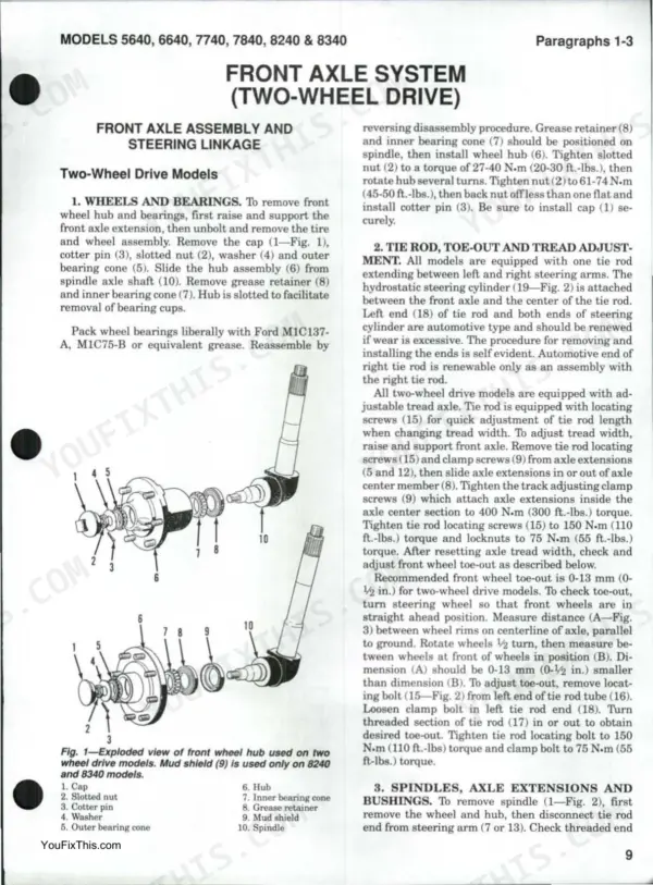
The screws retaining the axle pivot pin should be tightened to 70-90 N.m (52-66 ft.-lbs.) torque. For the front and rear pivot brackets, the attaching screws should be tightened to 317-388 N.m (234-286 ft.-lbs.) torque. p. 11
What are the error codes for hydraulic system failure on Ford 5640 tractors with electronic draft control?
The electronic draft control system displays error codes for various hydraulic system failures. Examples include Code 2 for poor or no signal from performance monitor radar, Codes 3, 4 & 5 for speed sensor errors, and Codes 6 & 7 for slip control potentiometer or circuit failure. Codes 14 & 15 indicate right hand load sensing pin or circuit failure. p. 208
How do I clear the transmission warning light and error codes on Ford 7740 tractors?
To clear error codes and reset the transmission warning light, turn the key start switch On and Off after completing a repair to the electrical system. To erase all stored error codes from memory, hold down the Digit Set button for about 10 seconds while in the error code recovery mode. p. 133
What format is this Ford 5640 & variants manual in?
Instant PDF download. You get the full 280-page searchable Shop Manual immediately after payment. Open it on your laptop, tablet, or phone right in the shop.
Can I print specific sections of this Ford 5640 & variants Shop Manual?
Yes. The PDF has no DRM restrictions, so print any page or section you need for your shop. Works with any standard printer.
Does this Ford 5640 & variants Shop Manual cover the hydraulic system?
Yes. The manual includes hydraulic circuit diagrams, system schematics, and component specifications with pressure ratings.


Reviews
There are no reviews yet.