


This is the FPT N Series F4G Tier 3 Technical and Repair Manual covering the F4GE9484F*J608 and F4GE9454J*J604 diesel engines used in Hyundai agricultural applications. Across 142 pages it documents this 4.5 liter, four cylinder engine from general specifications through a complete bench overhaul.You get the data a rebuild actually needs: clearance tables, tightening torques, injection pump values for the Bosch VE 4/12 F rotary mechanical pump, and step by step overhaul operations. The manual walks through engine removal at the bench, disassembly and reassembly of the front and rear components, and the checks and inspections that confirm each stage.A dedicated tools chapter lists the special equipment for the job, and the fuel section explains the feed pump, priming pump, and fuel filter. Written for qualified technicians, it is the reference for servicing or fully rebuilding these F4GE engines.
What's Inside This Fpt F4GE9484F*J608, F4GE9454J*J604 Manual
| System | Pages | Key Topics |
|---|---|---|
| Introduction | 5-18 | Preface to User’s Guideline Manual, Symbols, General Warnings, General Warnings on the Electric System, Conversions Between the Main Units of Measurement of the International System and Most Used Derived Quantities, Key of Lecture of the Headings and Footnotes |
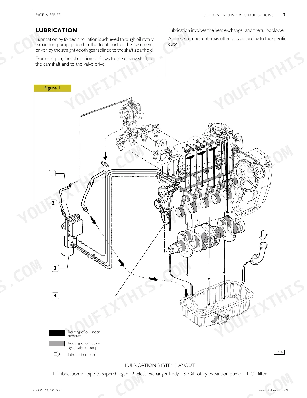
| General Specifications | 19-26 | Lubrication, Oil Vapour Recirculating System, Cooling System, Air Induction Boost Diagram, Inter-Cooled Engine Version, Exhaust Gas Re-Circulation System (EGR) |
| Fuel | 27-34 | 4-Cylinder Engines with Bosch Ve 4/12 F Rotary Mechanical Pump (Working Principles), Feed Pump (Example of Identification), Priming Pump, Fuel Filter |
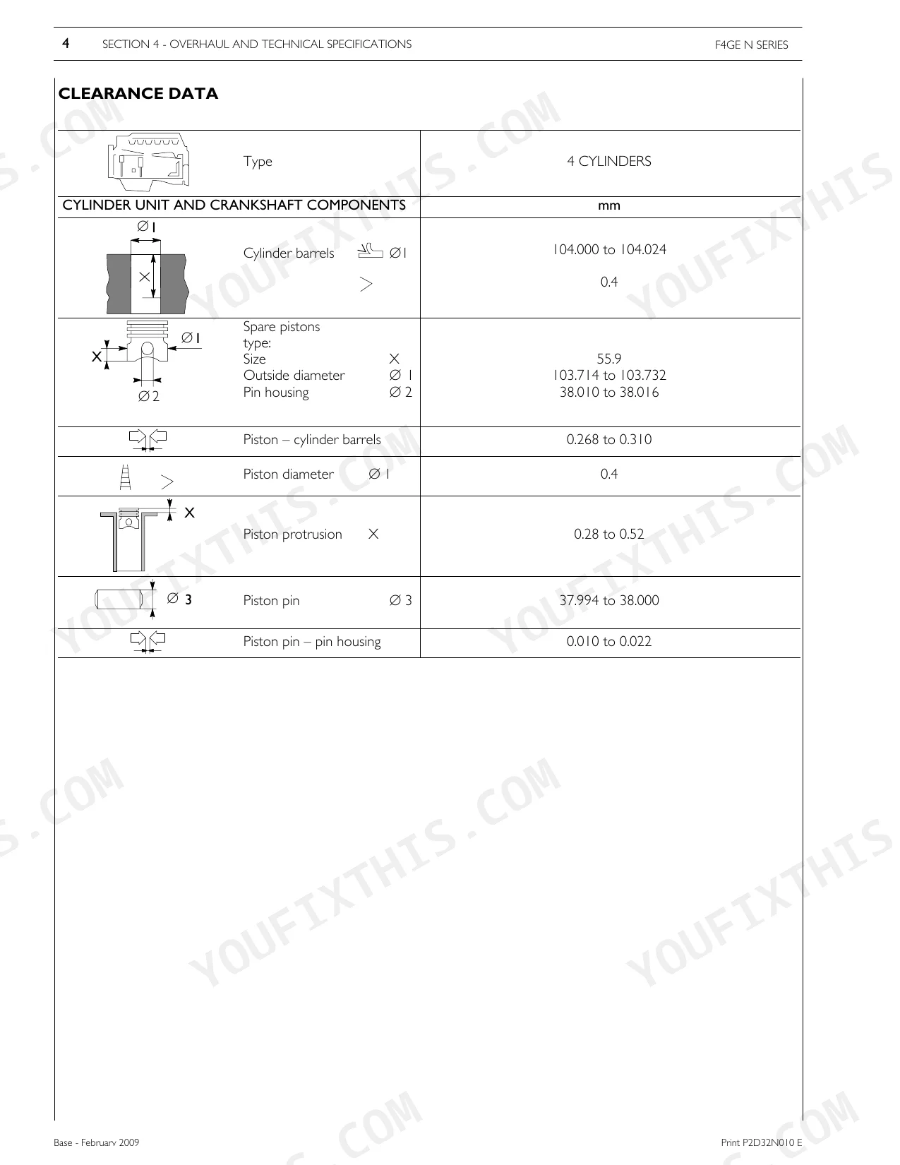
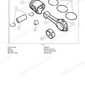
| Overhaul of the Engine | 37-44 | Clearance Data, General Information, Part One - Mechanical Components |
| Disassembly of Application Components | 45-52 | - |
| Installation of Front Components | 53-66 | Installation of Rear Components, Flywheel Installation |
| Rotary Feed Pump Disassembly and Assembly Procedure | 67-71 | Completion of Engine |
| Cooling Liquid Temperature Sensor | 72-78 | Checks and Inspections, Power Take-Off Disassembly and Assembly Procedure, Part Two - Electrical Equipment, Electrical Component Layout |
| Part Three - Troubleshooting | 79-88 | Electromagnets Assembled to Feed Pump |
| Maintenance Procedures | 89-92 | Part Four - Maintenance Planning, Maintenance Schedule |
| Alternator Belt Replacement | 93-96 | Check of Drive Belt Tensioning, Check of Fuel System, Fuel Filter Replacement |
| Overhaul and Technical Specifications | 97-130 | Clearance Data, Table of Pre-Delivery Values for Bosch Injection Pumps Ve 4/12 F, Engine Overhaul, Engine Removal at the Bench, Repair Operations |
| Tools | 131-138 | Revolving Stand for Overhauling Units, Injection Pump Gear Extractor, Tool to Remove Output Shaft Front Gasket, Tool to Remove Output Shaft Rear Gasket, Injector Pull-Out Tool |
| Appendix | 139-142 | Safety Prescriptions, Standard Safety Prescriptions, Prevention of Injury, During Maintenance, Respect of the Environment |
Quick Reference Specifications
| Specification | Value | Page |
|---|---|---|
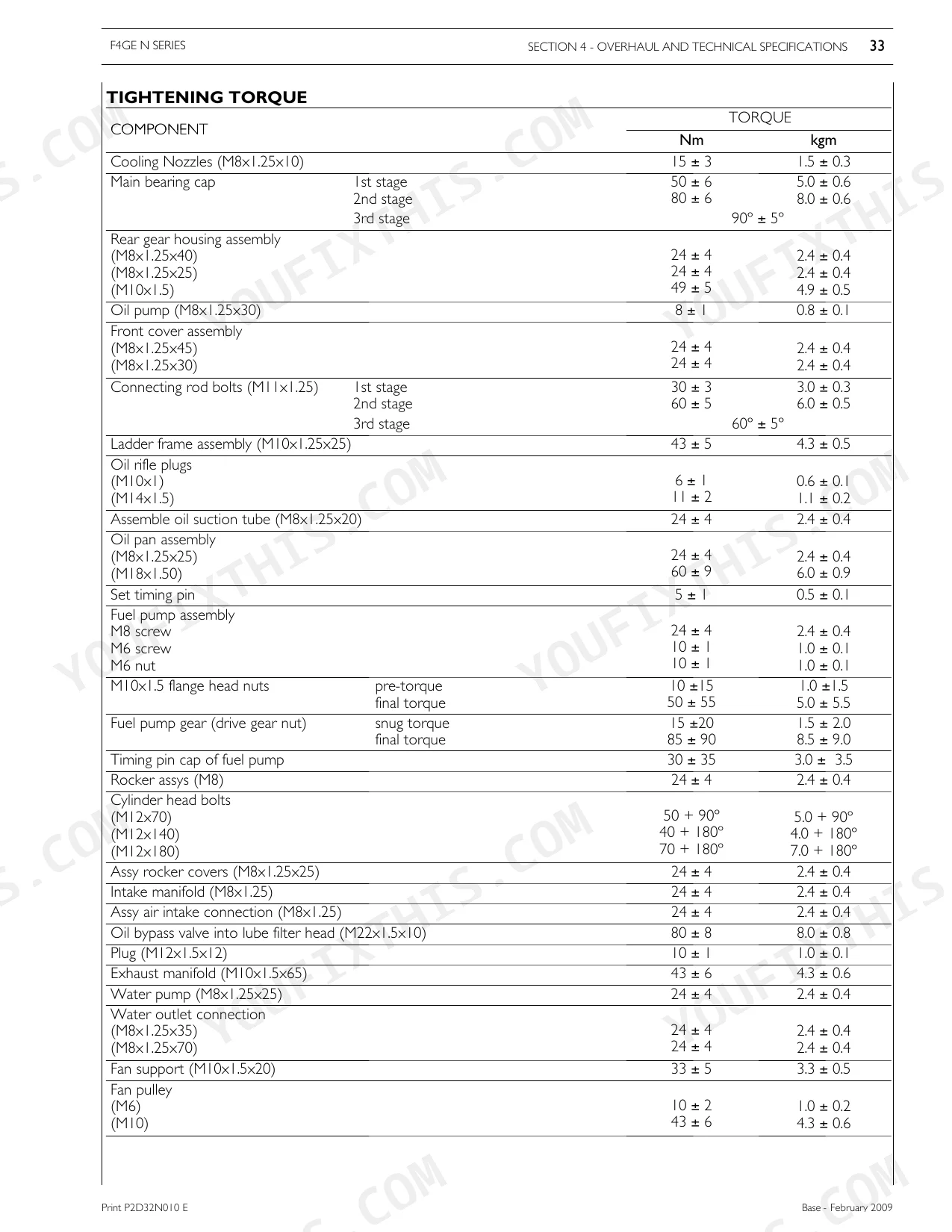
| Cylinder head bolts (M12x70) torque | 50 + 90º Nm | p. 129 |
| Cylinder head bolts (M12x140) torque | 40 + 180º Nm | p. 129 |
| Fuel injectors torque | 60 ± 5 Nm | p. 129 |
| Big end half bearings clearance | 0.250 to 0.500 mm | p. 101 |
| Half bearings - Crankpins clearance | 0.038 to 0.116 | p. 102 |
| Main bearings (No. 1 — 5) clearance | 0.040 to 0.106 | p. 102 |
| Main bearings (No. 2 — 3 — 4) clearance | 0.039 to 0.111 | p. 102 |
| Crankshaft Journals diameter | 82.990 ÷ 83.010 mm | p. 102 |
| Crankshaft Crankpins diameter | 68.987 ÷ 69.013 mm | p. 102 |
| Small end bush housing dimension | 40.987 to 41.013 mm | p. 101 |
| Big end bearing housing dimension | 72.987 to 73.013 mm | p. 101 |
| Oil bypass valve into lube filter head (M22x1.5x10) torque | 80 ± 8 Nm | p. 129 |
Fpt F4GE9484F*J608, F4GE9454J*J604 Common Problems This Manual Covers
Rod bearing failure from oil starvation
Low oil pressure, rod knock, or a sudden seizure on these engines is often traced to connecting rod bearing damage caused by lubrication loss. The clearance data and bearing specifications for diagnosing and reworking the bottom end are in the overhaul chapter.
Manual Section: Overhaul and Technical Specifications p. 97Bottom end damage after bearing wear
When a worn bearing spreads metal debris through the crankcase, the crankshaft journals and crankpins must be measured and often reground or replaced. The overhaul section gives the journal and crankpin diameters and the clearance limits.
Manual Section: Overhaul and Technical Specifications p. 97High pressure fuel leak or fire risk
A fuel smell or visible leak near the injection system is a serious safety concern on direct injection diesels. The fuel section explains the Bosch VE 4/12 F rotary pump, feed pump, priming pump, and fuel filter so leaks can be located and corrected.
Manual Section: Fuel p. 27Power loss and intake restriction
Loss of power, rough running, or increased smoke can follow carbon buildup and air path restriction. The general specifications chapter documents the air induction boost, inter-cooled version, and the exhaust gas re-circulation (EGR) system that affect breathing.
Manual Section: General Specifications p. 19Shortened oil service life
Oil consumption concerns or premature oil breakdown usually come from the wrong viscosity or missed intervals under heavy agricultural duty. The agricultural application chapter covers the maintenance planning, oil and filter service, and specific overhaul for these engines.
Manual Section: Agricultural Application p. 35Overhaul without the correct special tools
Rebuilding these engines calls for dedicated equipment such as the revolving overhaul stand, injection pump gear extractor, and the output shaft gasket removal tools. The tools chapter lists each special tool the procedures reference.
Manual Section: Tools p. 131Frequently Asked Questions
Which engines does this manual cover?
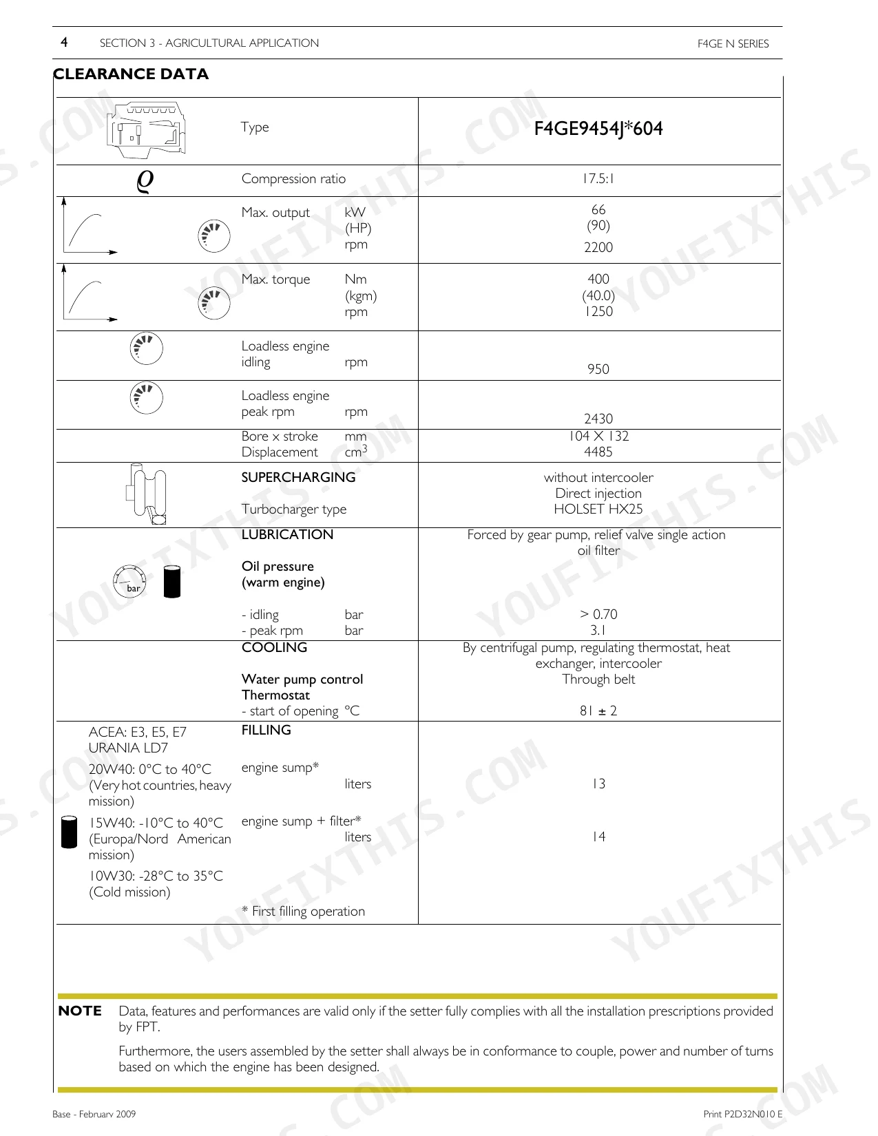
It covers the FPT N Series F4G Tier 3 diesel engines F4GE9484F*J608 and F4GE9454J*J604, as used in Hyundai agricultural applications. Both are the 4.5 liter, four cylinder variants.
Does it include cylinder head and rod torque specifications?
Yes. The Overhaul and Technical Specifications chapter lists tightening torques including the cylinder head bolts and the connecting rod bolt stages, along with the angular values used for the final passes. p. 97
Are clearance and rebuild data included?
Yes. The Overhaul and Technical Specifications chapter gives the clearance data, crankshaft journal and crankpin diameters, bearing clearances, and the pre-delivery values for the Bosch injection pumps. p. 97
Does it explain the fuel and injection system?
The Fuel chapter describes the 4-cylinder engines with the Bosch VE 4/12 F rotary mechanical pump, including working principles, the feed pump, priming pump, and fuel filter. p. 27
Is this manual a digital download?
Yes, it is an instant PDF download. The full 142-page searchable Technical and Repair Manual is available immediately after payment. Open it on a laptop, tablet, or phone right in the shop.
Am I able to print pages from this manual?
Absolutely. No DRM or copy protection. Print the whole manual or just the pages you need. Any home or office printer works.
Reviews
There are no reviews yet.