


This Gehl service manual covers the 40 Series skid-steer loaders: the SL4640, SL4840, SL5640, and SL6640, all built on Deutz 2011 series diesel engines. Publication 917002, it runs 232 pages and guides assembly and disassembly, removal and installation, adjustment, testing, and troubleshooting across the whole machine.Coverage spans specifications, safety, lubrication, the mainframe, wheel drives, controls, the hydrostatic and hydraulic systems, electrical, and the Deutz engines, supported by schematics, photographs, and line drawings. You get the values a repair needs, including hydraulic system pressure, reservoir and fuel capacities, axle housing and wheel nut torque, drive chain deflection, charge pressure settings, and tilt cylinder rod extension.Whether you are chasing a no crank fault, replacing a tilt solenoid valve, testing charge pressure, or rebuilding a control valve, this manual gives owners and independent mechanics the procedures to service an SL4640, SL4840, SL5640, or SL6640.
What's Inside This Gehl SL4640–SL6640 Series Manual
| System | Pages | Key Topics |
|---|---|---|
| A | 222 | Additional Safety Reminders 2-1, Air Cleaner and Exhaust Components - SL4640 Naturally Aspirated 10-6, Air Cleaner and Exhaust Components - SL4640 Turbocharged 10-7 |
| B | 222 | Battery Removal and Installation 10-18 |
| C | 223 | Chaincases 3-3, Charge Pressure Test and Adjustment 7-11, Chassis Components 4-3, Chassis Electrical Components 9-5, Control Arm Assembly Removal and Installation 6-19 |
| D | 224 | Operation - Right and Left Instrument Panels 9-1, Dimensional Specifications 1-2, Dome Light Bulb Replacement 9-25, Drive Chain Adjustment 5-2 |
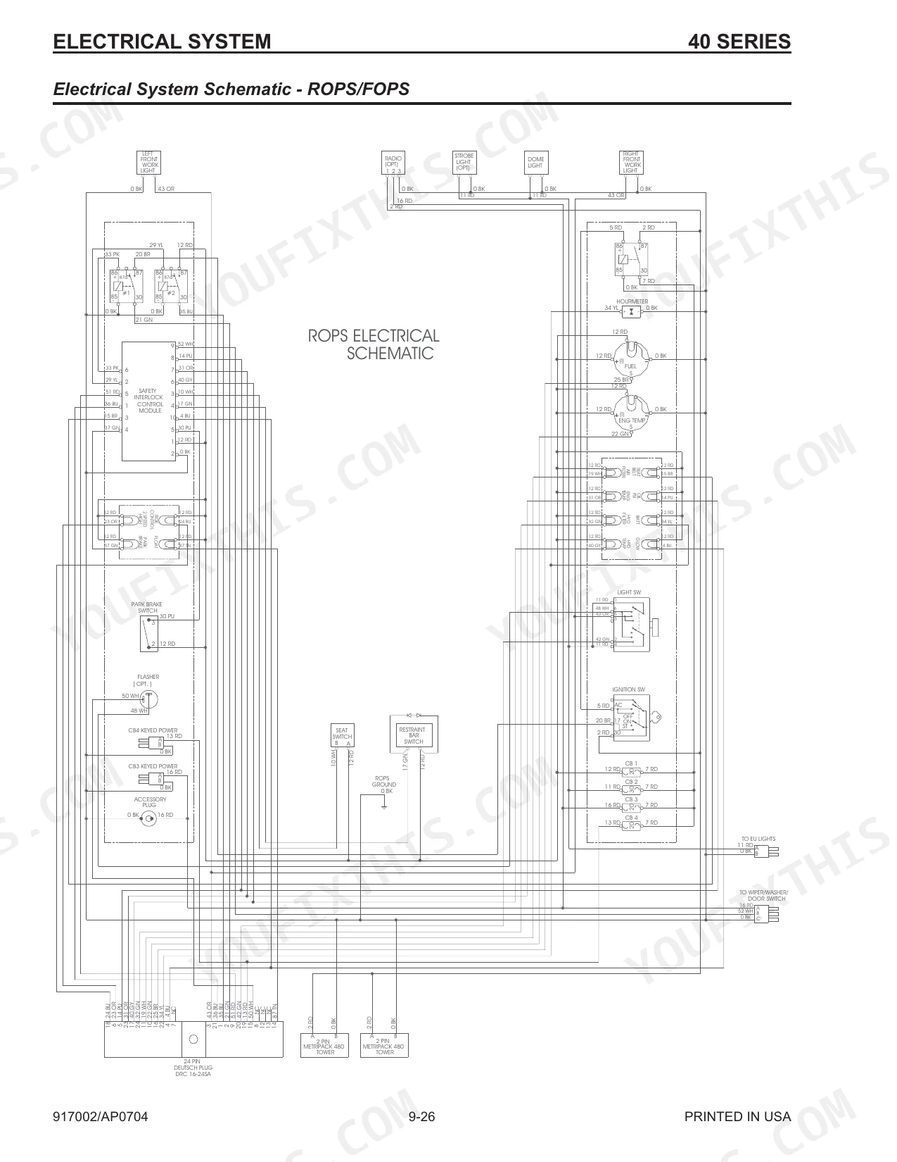
| E | 225 | Electric Auxiliary Hydraulics Control - Hand/Foot Components 6-26, Electrical Lights Components 9-23, Electrical System Chapter, Electrical System Schematic - Chassis 9-27 |
| F | 225 | Fan Belt Adjustment 10-21, Fan Shroud Adjustment 10-25, Fan Shroud Removal and Installation 10-24, Foot Throttle Adjustment - T-Bar and Dual Hand 6-38 |
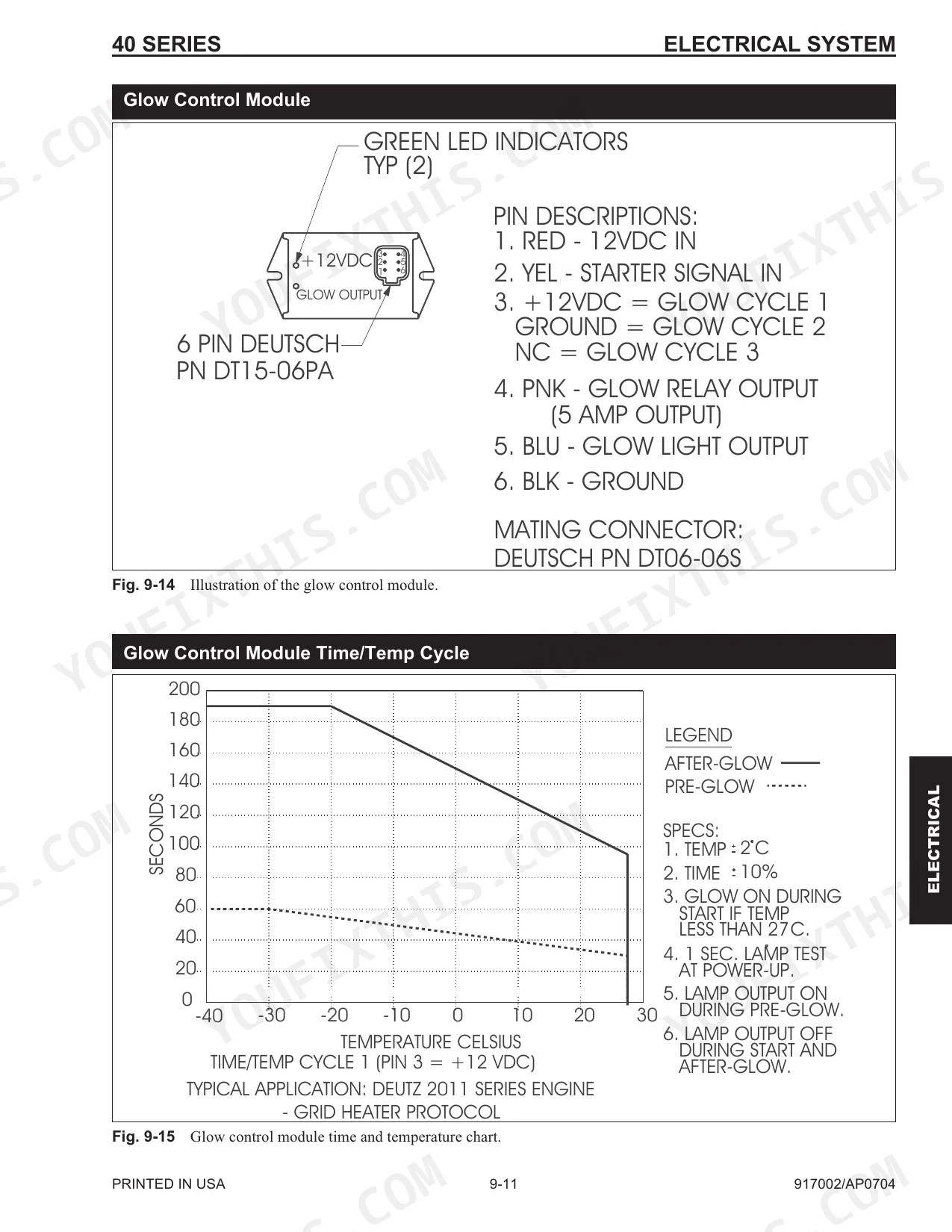
| G | 225 | Gear Pump Removal and Installation 8-34, Glow Control Module 9-11, Glow Control Module Test 9-12, Glow Control Module Time/Temp Cycle 9-11, Glow Relay Test 9-12 |
| H | 226 | Hand Throttle Adjustment - Hand/Foot 6-37, Hand Throttle and Throttle Cable Removal and Installation - Hand/foot 6-36, Hand Throttle Tension Adjustment 6-35, Hand Throttle |
| I | 227 | Ignition Switch Electrical Components 9-7, Interlock Control Module Test 9-14, Interlock Control Module Truth Table 9-15, Introduction 1-2 |
| L | 228 | Lift and Tilt Solenoid Valve - Disassembly and Assembly 8-41, Lift Cylinder Components 8-31, Lift Cylinder Removal and Installation 8-29, Lift Cylinder Test 8-22 |
| M | 228 | Mainframe Chapter, Mandatory Safety Shutdown Procedure 2-2, Master Circuit Breaker/Glow Circuit Breaker Test 9-8 |
| N | 228 | Neutral Centering Device Adjustment 6-18 |
| O | 229 | Oil Cooler Components - SL4640 and SL4840 Naturally Aspirated 10-11, Oil Cooler Components - SL4640 Turbocharged 10-12 |
| P | 229 | Pilot Valve Removal and Installation - Hand/foot Models 8-48, Pivot Tube Removal and Installation - T-Bar, Hand/Foot and Dual Hand 6-16, Power Relay Test 9-9 |
| R | 229 | Rear Grille and Engine Cover Components 4-5, Rear Grille Latch Removal and Installation 4-24, Rear Grille Removal and Installation 4-24, Rear Work Light Bulb Replacement 9-24 |
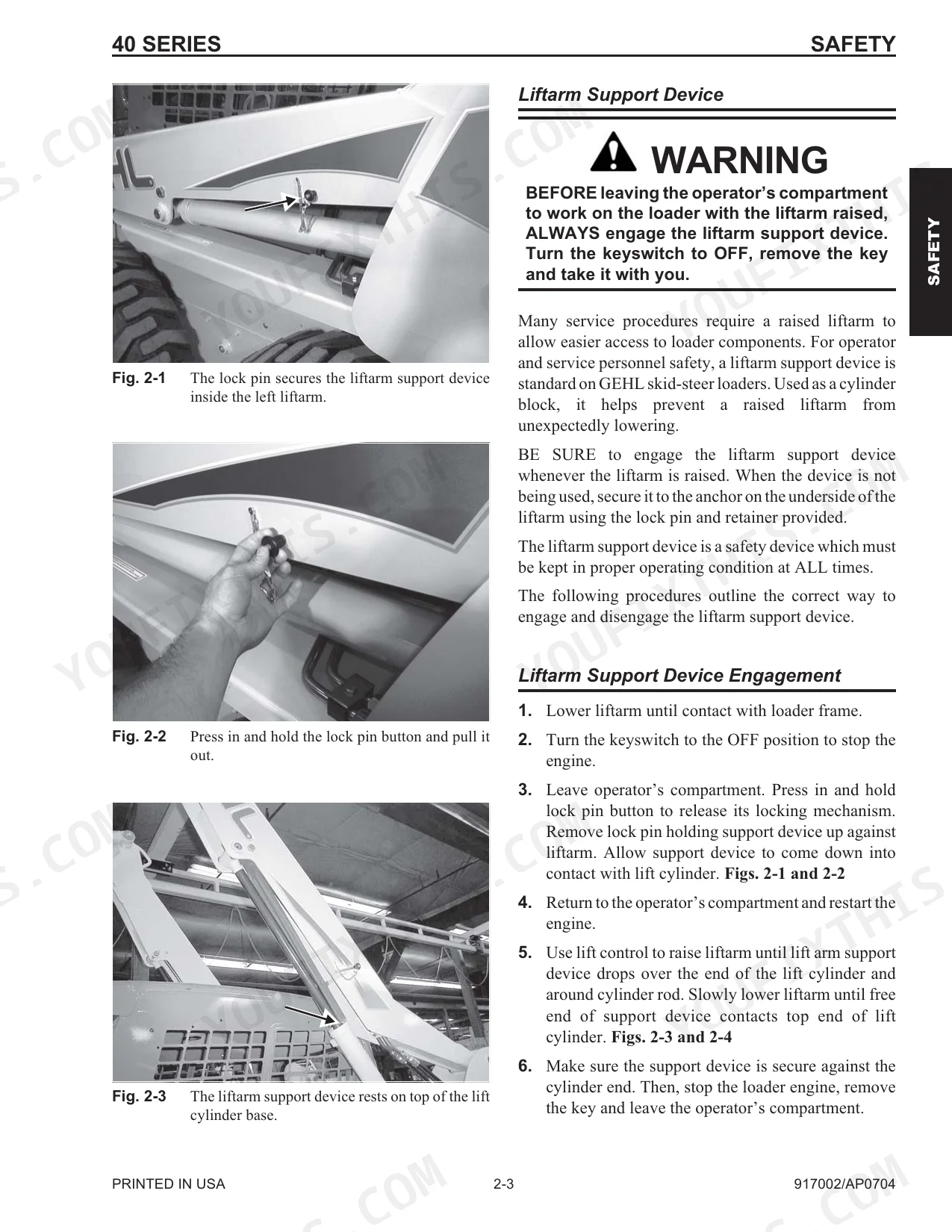
| S | 230 | Safety Chapter, Safety Lock Valves - Removal and Installation 8-39, Seat Removal and Installation 4-7, Seat Slide Replacement 4-7, Seat Switch Removal and Installation 9-19 |
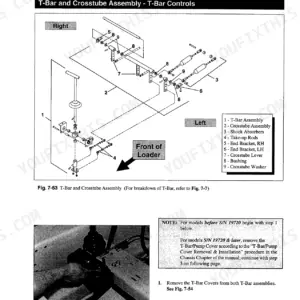
| T | 230 | Table of Contents 1-I, T-Bar Control Handle Assembly 6-9, T-Bar Control Models - Lift and Tilt Components 6-2, Throttle Components - Hand and Foot Components 6-32 |
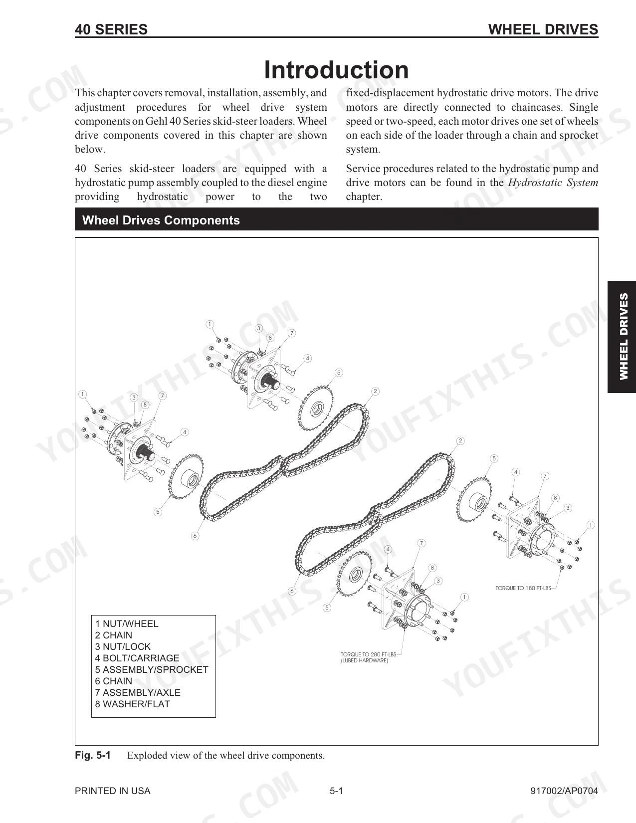
| W | 231-232 | Wheel Drives Chapter, Wheel Drives Components 5-1 |
Quick Reference Specifications
| Specification | Value | Page |
|---|---|---|
| All Models | ||
| Hydrostatic system fittings torque | 55 ft-lbs | p. 91 |
| Solenoid coil retaining nut torque | 45 in-lbs (5.1 N•m) | p. 147 |
| Chaincases (each) Capacity | 8 US qts (7,5 L) | p. 7 |
| Battery CCA | 950 CCA | p. 7 |
| Alternator Output | 95 A | p. 7 |
| Axle Housing Locknuts Torque | 280 ft-lbs (380 N•m) | p. 46 |
| Wheel Nut Torque | 180 ft-lbs (244 N•m) | p. 46 |
| SL4640 | ||
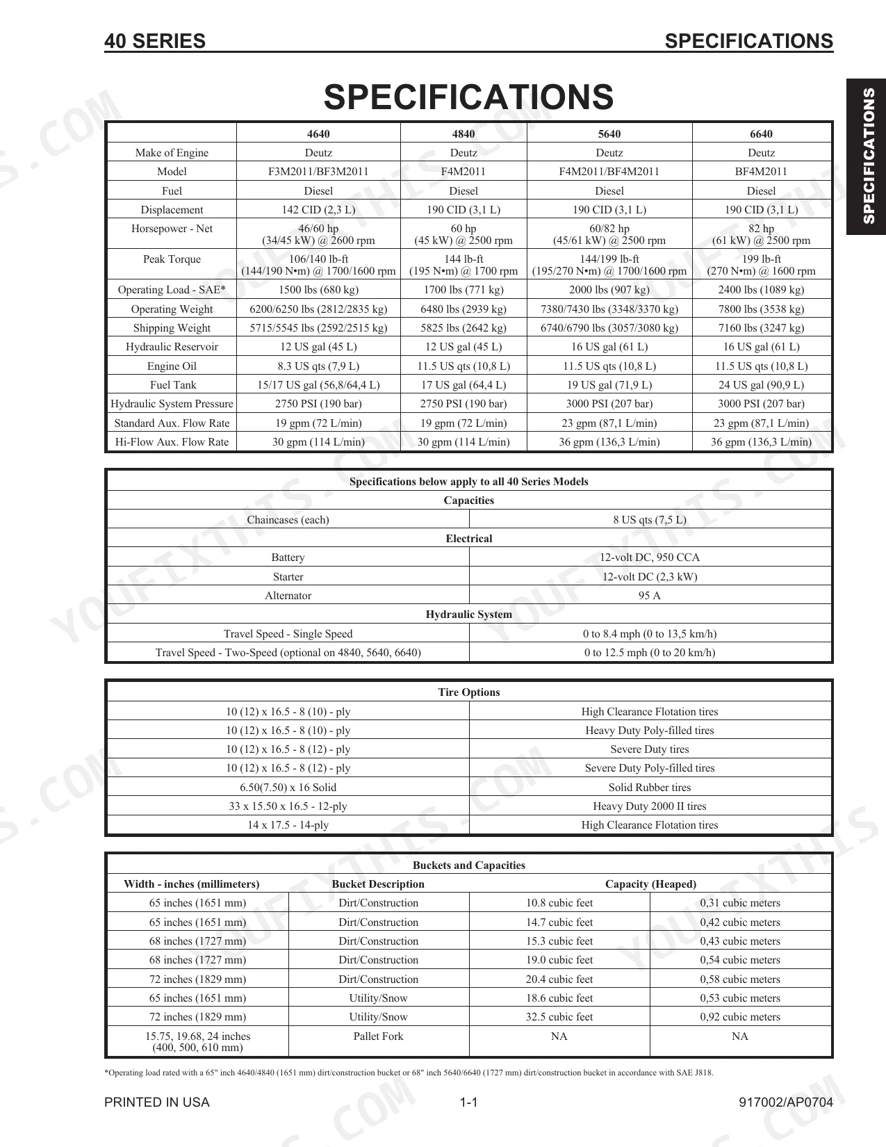
| Operating Load - SAE | 1500 lbs (680 kg) | p. 7 |
| SL4640/4840 | ||
| Hydraulic Reservoir Capacity | 12 US gal (45 L) | p. 7 |
| Engine Oil Capacity | 8.3 US qts (7,9 L) | p. 7 |
| Hydraulic System Pressure | 2750 PSI (190 bar) | p. 7 |
| SL4840 | ||
| Fuel Tank Capacity | 17 US gal (64,4 L) | p. 7 |
Gehl SL4640–SL6640 Series Common Problems This Manual Covers
Weak or intermittent hydraulic function
Hydraulics that are weak, intermittent, or inoperative usually trace to low oil, external leaks, or a control valve fault. The control valve removal and installation coverage walks through pulling and servicing the valve.
Manual Section: Control Valve Removal and Installation p. 150Bucket will not tilt while lift works
A bucket that will not tilt while the lift arm still works points to the tilt solenoid valve or its wiring. The lift and tilt solenoid valve disassembly and assembly coverage addresses this component.
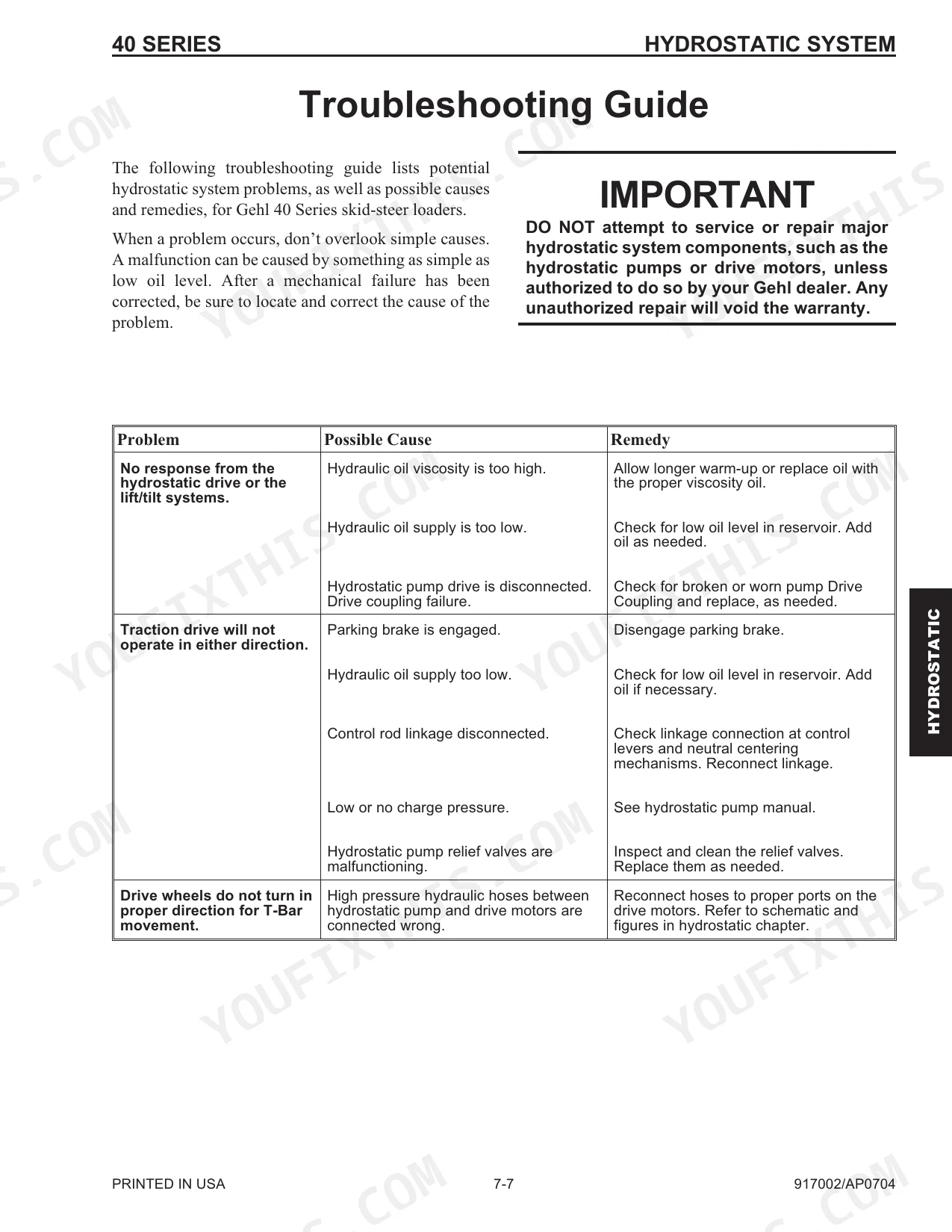
Manual Section: Lift and Tilt Solenoid Valve Disassembly and AssemblySluggish drive or low charge pressure
A drive that feels weak often traces to charge pressure being out of range. The charge pressure test and adjustment coverage shows how to check and set it on the hydrostatic system.
Manual Section: Charge Pressure Test and Adjustment p. 103No crank or starter and electrical fault
A no crank complaint usually means the battery, cables, relays, or starter circuit. The battery removal and installation coverage sits in the electrical work where these faults are traced.
Manual Section: Battery Removal and Installation p. 212Air intake leak or engine derate
Loose clamps or cracked intake tubes let air in and cost engine performance. The air filter element removal and installation coverage is part of the intake and engine service.
Manual Section: Air Filter Element Removal and Installation p. 211Drive chain stretch or wheel end wear
Skid steer wheel drives stretch their chains and wear axle bearings over time. The axle housing assembly removal and installation coverage handles the wheel end and drive components.
Manual Section: Axle Housing Assembly Removal and Installation p. 49Frequently Asked Questions
Which models does this manual cover?
It covers the Gehl 40 Series skid-steer loaders: the SL4640, SL4840, SL5640, and SL6640, all built on Deutz 2011 series diesel engines. The manual is publication 917002 and runs 232 pages.
Does it cover the tilt solenoid and control valve?
Yes. The control valve removal and installation coverage walks through servicing the valve, and the manual also details the lift and tilt solenoid valve where a bucket that will not tilt is diagnosed. p. 150
Are electrical schematics included?
Yes. The electrical coverage includes chassis electrical components and system schematics, along with tests for the glow control module, interlock module, and relays. p. 169
Does it list charge pressure and torque specifications?
Yes. The charge pressure test and adjustment coverage gives the hydrostatic setting, and the manual lists axle housing and wheel nut torque along with drive chain deflection. p. 103
How will I receive this Service Manual?
Immediate download of the complete 232-page searchable Service Manual. Access it on any device — laptop at your desk or phone in the field.
Am I able to print pages from this manual?
No restrictions at all. Print individual pages, full chapters, or the entire manual. The PDF is completely unlocked.
Are there hydraulic schematics in this Gehl SL4640–SL6640 Series manual?
Yes — complete hydraulic schematics with flow diagrams, valve configurations, and pressure specifications are included.


Reviews
There are no reviews yet.