


Part of the Kubota Repair Manuals.
All 579 pages of this Kubota L48 Workshop Manual (OEM #97897-12612) zero in on one machine: the L48 tractor with TL1150, TL1150SG front loader, and BT1100 backhoe. Inside, you get full wiring diagrams covering the starting, glow control, and charging systems; hydraulic schematics tracing circuit flow through the position control valve, steering controller, and directional valves; plus exploded views and step-by-step procedures spanning engine, transmission, clutch, brakes, and both attachments. Troubleshooting charts cover the hydrostatic transmission, wet disc brakes, front axle, and hydraulic system symptoms with probable causes and fixes. Torque the TL1150SG control valve mounting bolts to 36.6–43.4 N·m and the tie-rod lock nut to 117–137 N·m. Your machine is down — stop digging through forums. Download now, search by keyword, and pull up the right spec before you touch the first wrench.
What's Inside This Kubota L48, TL1150, BT1100, TL1150SG Manual
| System | Pages | Key Topics |
|---|---|---|
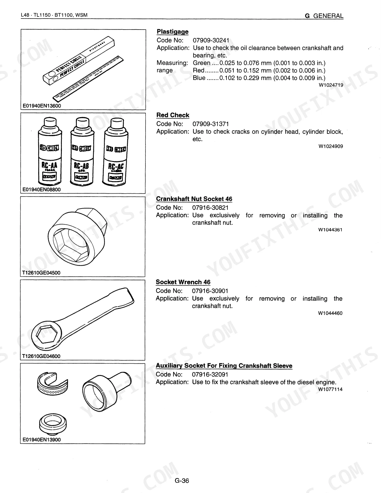
| General Information | - | Safety Decals, Tractor Identification, Fluid Capacities, Maintenance Schedule, Special Tools |
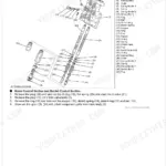
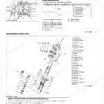
| Engine Mechanism | - | Fuel System, Governor Operation, Steel Ball Mechanism, Control Rack |
| Engine Servicing | - | Engine Overheated, Cylinder Head Surface, Valve Seat, Valve Face, Valve Stem, Valve Recessing, Valve Timing, Valve Spring |
| Clutch Mechanism | - | Features, Linkage Mechanism, Engaged Operation, Disengaged Operation |
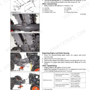
| Clutch Servicing | - | Clutch Mounting Screw, Release Fork Setting Screw, Engine to Clutch Housing Mounting Stud Bolt, Cap Nut for Hydraulic Pipe, Clutch Pedal, Clutch Pedal Stopper Bolt, Transmission Fluid, Battery |
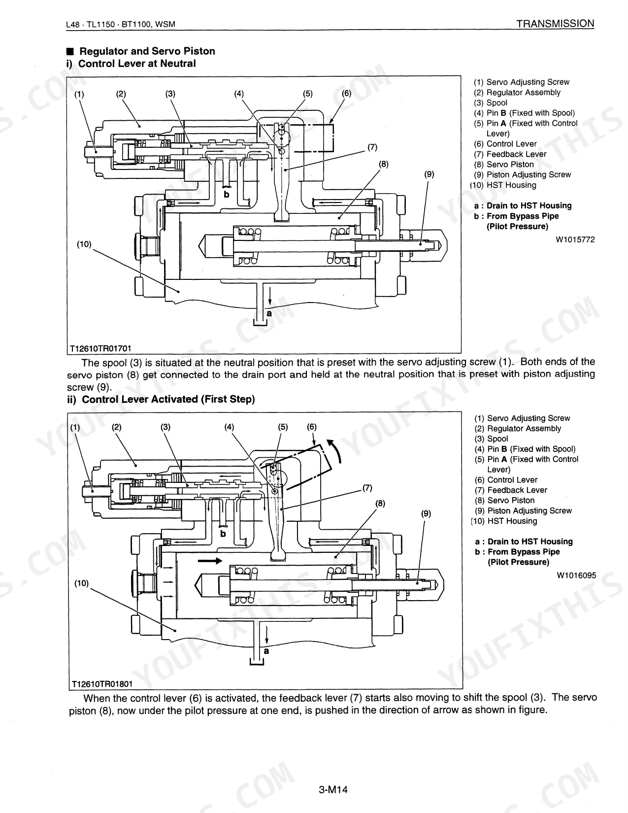
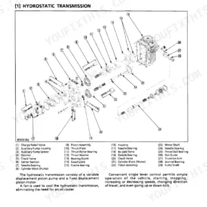
| Transmission Mechanism | - | Hydrostatic Transmission, Range Gear Shift, PTO Shift, Differential Gear, Oil Flow |
| Transmission Servicing | - | Oil Heat, Machine Neutral Position, System Operates in One Direction Only, Gear to Spline, Spiral Bevel Pinion, Differential Case Bore, Differential Pinion Shaft, Differential Pinion |
| Rear Axle Mechanism | - | Features, Final Reduction System, Planetary Gear, Differential Side Gear |
| Rear Axle Servicing | - | Rear Axle, Planetary Gear, Pillow Block, Rear Axle Nut, Rear Axle Cover |
| Brakes Mechanism | - | Features, Wet Disc Brakes, Reduced Wear, Operation |
| Brakes Servicing | - | Brake Pedal, Brake Case, Brake Lever Link Shaft, Brake Lever Link Bushing, Cam Plate, Brake Disc, Plate, Brake Rod |
| Front Axle Mechanism | - | Structure, Front Wheel Alignment, Camber, Toe-In |
| Front Axle Servicing | - | Front Wheels, Front Axle, Tie-Rods, Bevel Gear Case, Front Gear Case, Bevel Gear and Bevel Gear Shaft, Bevel Gear Case Gears, Axle |
| Steering Mechanism | - | Steering Linkage, Hydraulic Circuit, Hydraulic Pump, Steering Controller, Steering Cylinder |
| Steering Servicing | - | Hydraulic Pump, Relief Valve, Steering Controller, Steering Cylinder |
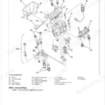
| Hydraulic System Mechanism | - | Hydraulic Circuit, Position Control Valve, Directional Valve, Relief Valve, Hydraulic Cylinder |
| Hydraulic System Servicing | - | Hydraulic Block, Directional Valve, Relief Valve, Hydraulic Cylinder, Cylinder Safety Valve, Hydraulic Pump, Position Control Valve |
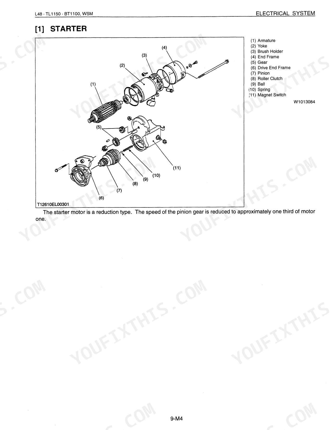
| Electrical System Mechanism | - | Wiring Diagram, Starting System, Glow Control System, Charging System, Lighting System |
| Electrical System Servicing | - | Safety Switch, Engine Stop Solenoid, Charging System, Alternator, Ic Regulator, Lighting System, Easy Checker, Gauges |
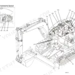
| Frames Servicing | - | Tightening Torques, Front Loader Assembly, Canopy, ROPS, Tractor Frame Disassembly |
| Front Loader Mechanism | - | Specifications, Hydraulic System, Self-Leveling Valve, Control Valve Assembly, Boom/Bucket Cylinder |
| Front Loader Servicing | - | Self-Leveling Valve, Boom Cylinder, Control Valve, Bucket Cylinder, Inlet Section, Outlet Section, Piston Rod |
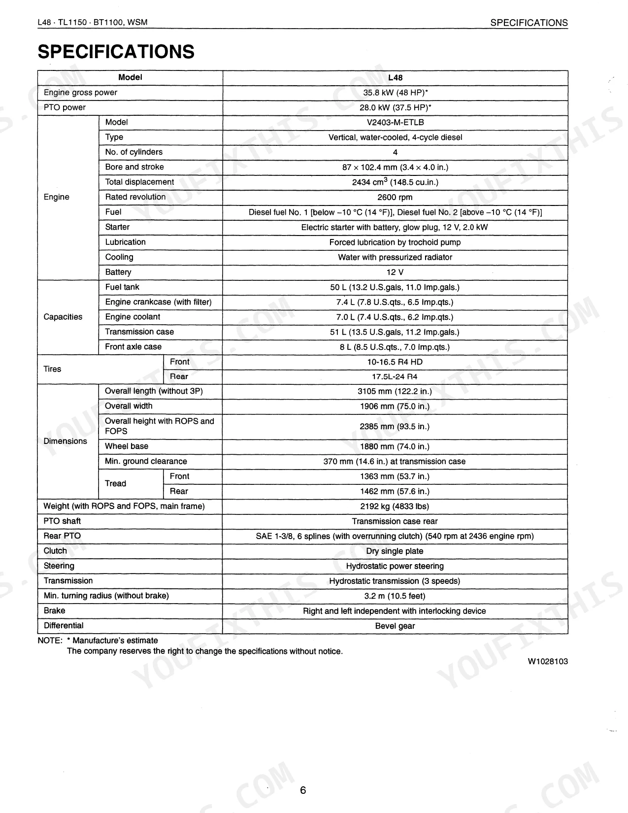
Quick Reference Specifications
| Specification | Value | Page |
|---|---|---|
| L48, TL1150, BT1100 | ||
| General Use Screws, Bolts and Nuts Torque (M6, Grade 8.8) | 9.8 to 11.2 N·m (1.0 to 1.1 kgf·m, 7.2 to 8.3 ft-lbs) | p. 18 |
| Hydraulic System Troubleshooting Guide | Refer to page 8-S1 for a table of symptoms, probable causes, and solutions. | p. 495 |
| Tie-rod lock nut torque | 117 to 137 N·m (12 to 14 kgf·m, 86.1 to 101.3 ft-lbs) | p. 409 |
| Tie-rod end nut torque | 156.9 to 175.5 N·m (16.0 to 18.0 kgf·m, 115.7 to 130.2 ft-lbs) | p. 409 |
| Front Wheel Alignment Toe-in (Factory Specification) | 2 to 8 mm (0.08 to 0.32 in.) | p. 407 |
| Front Wheel Alignment Axial Sway (Factory Specification) | 5.0 mm (0.197 in.) | p. 407 |
| TL1150SG | ||
| Control valve mounting bolt and nut torque (Front Loader) | 36.6 to 43.4 N·m (3.7 to 4.4 kgf·m, 27 to 32 ft-lbs) | p. 576 |
| Control valve section mounting nut (3/8) torque (Front Loader) | 45 N·m (4.6 kgf·m, 33 ft-lbs) | p. 576 |
Kubota L48, TL1150, BT1100, TL1150SG Common Problems This Manual Covers
Kubota L48 front wheel alignment feels sloppy and tie rod ends show excessive play during operation.
Inspect the front-end steering linkage components. Adjust the front wheel alignment toe-in to 2 to 8 mm (0.08 to 0.32 in.) as shown on page 407. Tighten the tie-rod lock nut to 117 to 137 N·m (86.1 to 101.3 ft-lbs) on page 409.
Manual Section: Frames Servicing p. 407Hydrostatic pedal linkage develops slack and feels loose or inconsistent when pressing forward or reverse.
Check the hydrostatic pedal bushings and pins for wear. Remove damaged linkage components and replace them. Torque the M6 grade 8.8 mounting bolts to 9.8 to 11.2 N·m (7.2 to 8.3 ft-lbs) using the general specifications table on page 18.
Manual Section: Transmission Servicing p. 18Loader control valve mounting hardware vibrates loose and causes poor hydraulic response on the front arms.
Verify the control valve is seated correctly. Tighten the control valve mounting bolts and nuts to 36.6 to 43.4 N·m (27 to 32 ft-lbs) as specified on page 576. Inspect the surrounding hydraulic fittings for signs of leakage before testing the boom.
Manual Section: Front Loader Servicing p. 576Low or falling charge pressure after warm up and machine loses hydrostatic performance after 15 minutes.
Drain the hydraulic fluid and inspect the suction-side line for leaks. Consult the troubleshooting procedures on page 169 to isolate the charge pump. Replace worn internal transmission components and torque general M6 case bolts to 9.8 to 11.2 N·m (7.2 to 8.3 ft-lbs).
Manual Section: Transmission Mechanism p. 169Frequently Asked Questions
What are the torque specs for Kubota L48 wheel lug nuts / loader pins / backhoe mounts?
For the Kubota L48, the front wheel mounting nuts should be tightened to 196 N·m (20.0 kgf·m, 144.7 ft-lbs) and the rear wheel mounting nuts to 304 N·m (31.0 kgf·m, 224.2 ft-lbs). For loader components, the boom and bucket cylinder piston mounting nuts require 271.2 to 298.3 N·m (27.7 to 30.4 kgf·m, 200 to 210 ft-lbs). Backhoe cylinder support mounting screws are 176 to 211 N·m (18.0 to 21.5 kgf·m, 130 to 156 ft-lbs), and boom cylinder piston mounting nuts are 414 to 441 N·m (42.2 to 44.9 kgf·m, 305 to 325 ft-lbs). p. 18
Why does my Kubota L48 crank but not start?
If your Kubota L48 cranks but does not start, probable causes include a lack of fuel, air or water in the fuel system, a clogged fuel filter, or incorrect injection timing. Other issues could be a worn fuel camshaft, a malfunctioning injection pump, or a defective engine stop solenoid. Solutions range from replenishing fuel (page G-8) and bleeding the fuel system (page G-32) to replacing the engine stop solenoid (page 9-S13). p. 196
Why is my Kubota L48 hydraulic system acting sluggish?
A sluggish hydraulic system on your Kubota L48 can stem from several issues, such as a malfunctioning position control valve, a weakened or broken relief valve spring, or a clogged oil filter. For front loader operations, specific causes include a self-leveling valve malfunction or defective boom cylinders. If the backhoe is affected, insufficient transmission fluid or a hydraulic pump malfunction could be the cause. Solutions typically involve repair or replacement of faulty components, adjusting linkages, or refilling fluids. p. 305
How will I receive this Kubota L48, TL1150, BT1100, TL1150SG Workshop Manual?
You get a 579-page searchable PDF that downloads instantly after checkout. Open it on your laptop, tablet, or phone, bring it right to the shop floor.
Can I print specific sections of this Kubota L48, TL1150, BT1100, TL1150SG?
The PDF is DRM-free. Print whatever sections you need to take out to the shop. Standard letter or A4 paper works.
Does this Kubota L48, TL1150, BT1100, TL1150SG manual include hydraulic?
Yes, complete hydraulic schematics with flow diagrams, valve configurations, and pressure specifications are included.


Reviews
There are no reviews yet.