


Part of the Hyundai Repair Manuals.
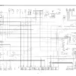
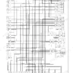
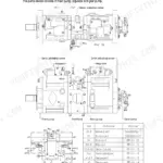
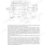
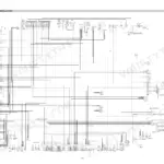
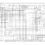
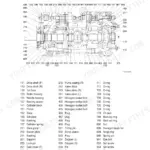
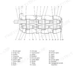
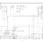
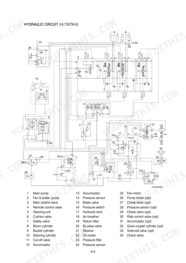
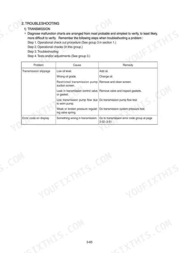
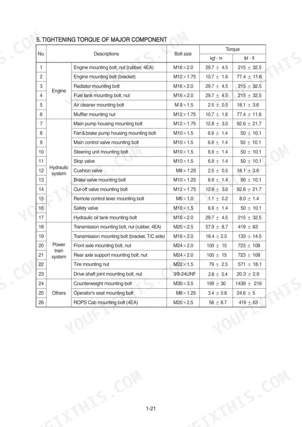
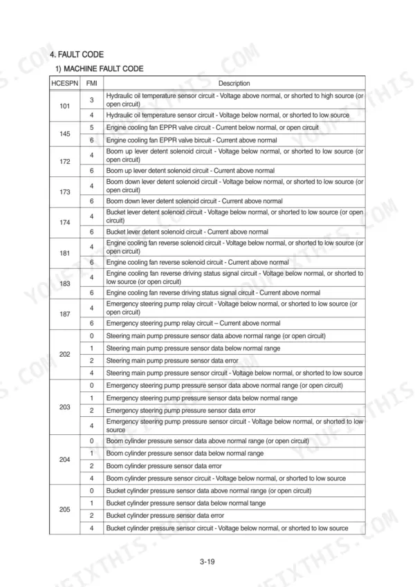
All 521 pages of this Hyundai HL730-9, HL730XTD-9, HL730TM-9 Service Manual PDF focus on one job: putting your wheel loader back to work. Inside: factory electrical circuit diagrams with connector pinouts and component specs, hydraulic circuit schematics covering the main pump and the full work equipment system, plus error code tables that turn a flashing monitor into a real diagnosis. You also get complete disassembly and assembly procedures for the power train, brakes, and steering, each backed by operational checks and adjustment tests. Set the steering unit pressure between 20.5 and 21.5 MPa, then pull the tire mounting nuts to 79 kgf·m (571 lbf·ft) before that wheel goes back on. A loader waiting on forum answers earns nothing. Bookmarked with a real text layer; download it, search any spec by keyword, and get wrenching.
What's Inside This Manual
| System | Pages | Key Topics |
|---|---|---|
| General | 1-9 | Safety Hints, Specifications, Operational Checkout Record Sheet |
| Electrical System | 10-38 | Component Location, Electrical Circuit, Monitoring System, Electrical Component Specification, Connectors, Troubleshooting |
| Engine | 39-45 | Structure and Function, Engine Speed and Stall RPM, Fuel Warmer System |
| Power Train Structure and Function | 47-106 | Power Train Component Overview, Torque Converter, Transmission, Tire and Wheel, Fault Codes |
| Power Train Checks and Adjustments | 107-119 | Power Train Operational Checks, Troubleshooting, Transmission Measuring Points, Tests and Adjustments |
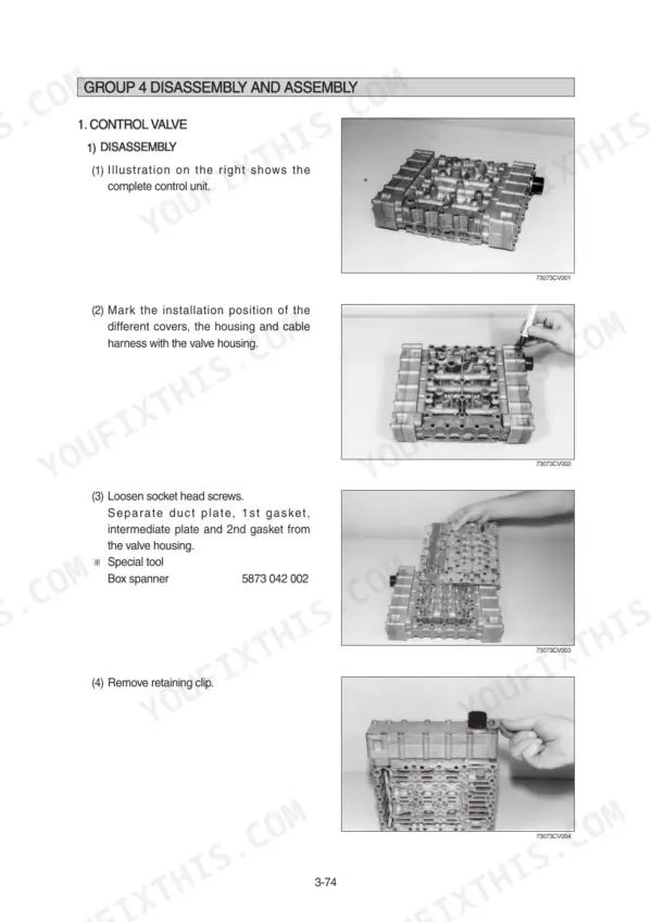
| Power Train Disassembly and Assembly | 120-254 | Transmission, Control Valve, Service Brake, Planetary Reduction, Differential, Pinion, Swinging Support, Negative Brake |
| Brake System | 255-294 | Structure and Function, Operational Checks and Troubleshooting, Tests and Adjustments, Disassembly and Assembly |
| Steering System | 295-354 | Structure and Function, Operational Checks and Troubleshooting, Tests and Adjustments, Disassembly and Assembly |
| Work Equipment | 355-521 | Hydraulic System Outline, Hydraulic Circuit, Main Pump, Component Location, Electrical Circuit, Monitoring System |
Quick Reference Specifications
| Specification | Value | Page |
|---|---|---|
| All Models | ||
| Tire mounting nut | 79 ± 2.5 kgf·m (571 ± 18.1 lbf·ft) | p. 32 |
| Steering cylinder Bore dia×Rod dia×Stroke | Ø 60×Ø35×412 mm | p. 30 |
| Torque limit for cover socket head screws | 0.56 kgf·m (4.06 lbf·ft) | p. 126 |
| Torque limit for duct plate socket head screws | 0.97 kgf·m (7.0 lbf·ft) | p. 127 |
| Steering unit pressure | 20.5-21.5 MPa | p. 317 |
| Torque wrench | 0-7.1 kgf·m | p. 319 |
| Gland tightening torque | 65 ± 7 kgf·m (463 ± 51 lbf·ft) | p. 343 |
| Engine Oil Quantity | 11L | p. 29 |
| Main Relief Valve Set Pressure | 250 kgf/cm2 | p. 30 |
| HL730-9 | ||
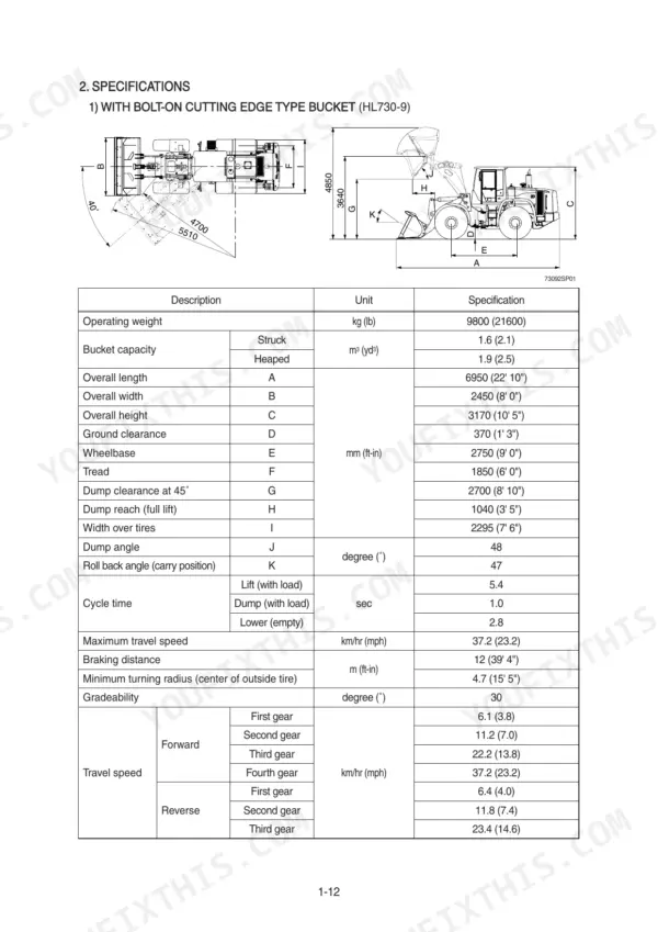
| Operating Weight, HL730-9 | 9800 kg | p. 23 |
| HL730XTD-9 | ||
| Operating Weight, HL730XTD-9 | 10000 kg | p. 24 |
| HL730TM-9 | ||
| Operating Weight, HL730TM-9 | 10200 kg | p. 25 |