
![Hyundai HSL800T Repair Manual [Skid Steer Loader]](https://youfixthis.com/wp-content/uploads/2016/02/2016-02-16_11-07-01-1-300x300.jpg)

Part of the Hyundai Repair Manuals.
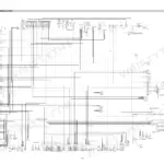
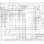
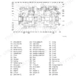
Need factory specs for your Hyundai HSL810 skid steer loader? This 132-page Hyundai HSL810 service manual PDF walks you through the whole machine, from the hydrostatic drive pumps to the boom and bucket cylinders. You get complete wiring diagrams with connector destinations, a full hydraulic circuit diagram, and component testing procedures for main control valve pressure, charge pump pressure, and auxiliary pump flow. Step-by-step teardowns take you through the main pump, travel motor, self level valve, and main control valve spools, backed by a troubleshooting section that chases faults across travel hydraulics, power train, and the electrical system. Set the charge pressure relief valve at 290 psi (20 bar), and torque SAE size 8 flare fittings to 5.1 to 6.3 kgf·m. No more chasing electrical gremlins with a multimeter and a prayer. Bookmarked with a live text layer: pull it up on your phone in the shop and get wrenching.
What's Inside This Hyundai HSL810 Manual
| System | Pages | Key Topics |
|---|---|---|
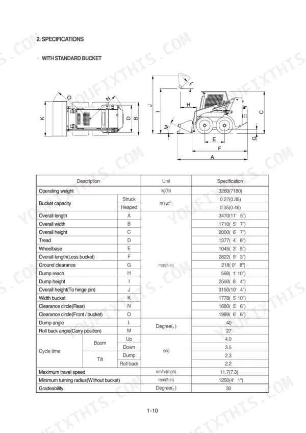
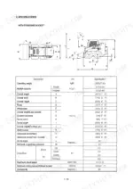
| General | 1-21 | Safety Hints, Machine Specifications (Bucket Capacity, Cycle Time, Engine Compression Ratio and Cooling Method), Axial Tandem Piston Pump Data, Maintenance Schedule |
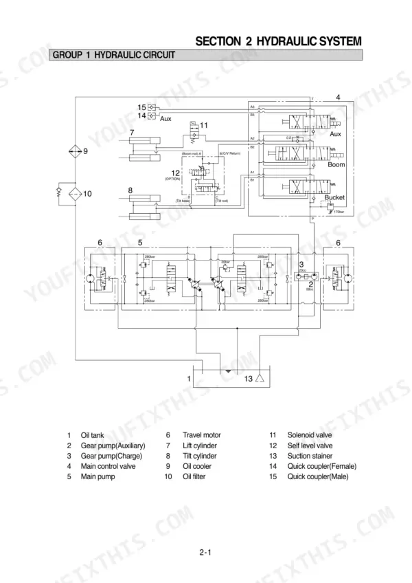
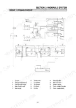
| Hydraulic Circuit and Component Testing | 22-29 | Hydraulic Circuit Diagram, Component Testing Procedures, Main Control Valve Pressure, Auxiliary Pump Flow, Charge Pump Pressure, Hydrostatic Control Pump Pressure |
| Self Level Valve | 30-35 | Structure, Hydraulic Circuit, Self Leveling Operation, Bucket Cylinder Extension, Retracting Boom Cylinder |
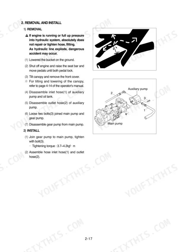
| Auxiliary Pump | 36-41 | Function, Design, Pressure Balance, Removal and Install, Disassembly, Reassembly |
| Main Pump | 42-62 | Removal and Install, General Description, Transmission Hydraulic Support System, Start Up and Maintenance, Troubleshooting, Inspections and Adjustments |
| Travel Motor | 63-72 | Removal and Install, Disc Valve and Balance Plate, Channel Plate, Gear Wheel Set and Input Gear, Cardan Shaft and Bearing Housing, Reassembly with Dust Seals and Back-Up Rings |
| Main Control Valve | 73-79 | Removal and Install, Structure, Boom Spool Disassembly, Bucket Spool Disassembly, Auxiliary Spool Disassembly, Check Valve, Main Relief Valve |
| Boom and Bucket Cylinder | 80-84 | Removal and Install, Boom Cylinder, Bucket Cylinder, Structure, Disassembly and Assembly |
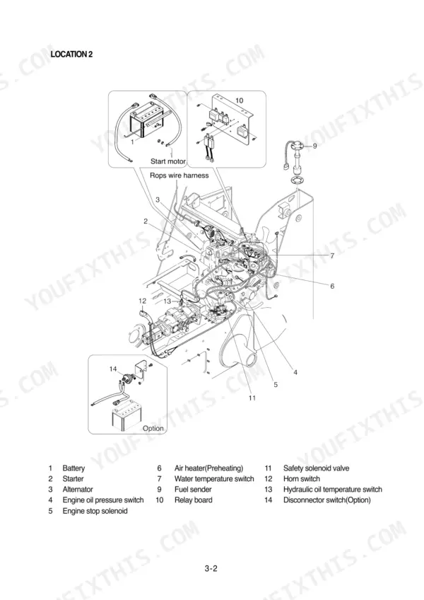
| Electrical System | 85-104 | Component Location, Wiring Diagram, Electrical Component Specification, Connector Destination |
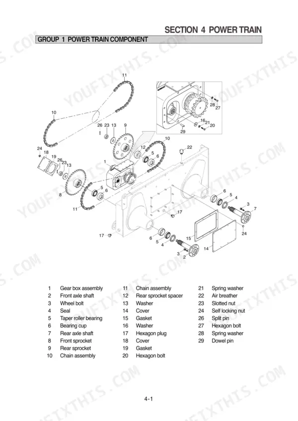
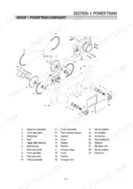
| Power Train | 105-114 | Power Train Component, Front and Rear Axle, Gear Box |
| Control | 115-123 | Hand Control, Foot Control, Parking Brake, Attachment Holder |
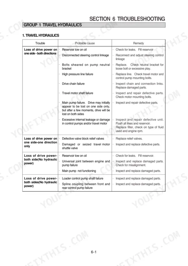
| Troubleshooting | 124-132 | Travel Hydraulics, Boom and Bucket Hydraulic, Power Train, Control, Electrical System |
Quick Reference Specifications
| Specification | Value | Page |
|---|---|---|
| Torque for SAE size 4 flare fitting | 1.1 - 1.6 kgf·m | p. 17 |
| Torque for SAE size 6 flare fitting | 2.6 - 3.1 kgf·m | p. 17 |
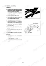
| Nut(2) tightening torque | 14.4 ± 2.2 kgf·m | p. 42 |
| Bolt(3) tightening torque | 6.9 ± 1.4 kgf·m | p. 42 |
| Charge pressure relief valve | 290 psi (20 bar) | p. 46 |
| Pump bolt tightening torque | 61~68 Nm | p. 41 |
| Charge pressure | 220 psi (15.2 bar) | p. 46 |
| M1 System pressure port A gauge | 6000 psi or 400 bar | p. 51 |
| Engine rated gross horse power | 70 ps at 2500 rpm | p. 13 |
| Engine oil quantity | 9.4 L | p. 15 |
| Main relief valve pressure | 170 kg/cm2 | p. 14 |
| Main control valve system pressure | 2400-2500 psi | p. 25 |
Hyundai HSL810 Common Problems This Manual Covers
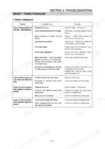
Hyundai HSL810 loses drive power on one side, other track pulls fine
Check the reservoir oil level first, then work through the travel hydraulics chart on page 125. Test charge pump pressure against the 300 psi spec on page 27; a low reading points to the charge relief valve or pump. Inspect the pump neutral bracket and drive chain before condemning the travel motor.
Manual Section: Travel Hydraulics Troubleshooting p. 125Boom raises slow and jerky, bucket weak under load, hydraulic oil running hot
Check the reservoir level and hydraulic filters before pulling anything apart. Test main control valve system pressure using the procedure on page 25; you should see 2400-2500 psi at rated engine speed. A low reading means a tired main relief valve or internal leakage in the main control valve, covered starting on page 73.
Manual Section: Boom and Bucket Hydraulic Troubleshooting p. 22Starter will not engage or cranks slowly, charge lamp stays on after startup
Verify battery voltage and clean both cable terminals before blaming the starter. Trace the start and charge circuits with the wiring diagram on page 87, checking the solenoid signal at each connector along the way. Test alternator output with the engine at its rated 2500 rpm; no charge with good belt tension means the alternator comes out.
Manual Section: Electrical System Troubleshooting p. 85Loud clunk from the chain case when reversing, sprocket feels loose on shaft
Remove the chain case inspection cover and check chain tension and sprocket wear; torque the cover nuts to 103 Nm on reassembly per page 110. Re-torque the sprocket shaft nut to 137 Nm as shown on page 114. Replace the chain if rollers are cracked or stretched; the drivetrain parts breakdown starts on page 106.
Manual Section: Power Train p. 114Hydraulic fittings weeping oil around the boom base, wet film after every shift
Clean the fitting dry and confirm the SAE size before putting a wrench on it. Torque flare fittings to the chart on page 17: a size 8 takes 5.1 to 6.3 kgf·m, a size 12 takes 11.6 to 12.6 kgf·m. Overtightening cracks the flare seat; if it still weeps after a proper torque, replace the hose.
Manual Section: General p. 17Frequently Asked Questions
How do I troubleshoot a Hyundai HSL810 that won’t start?
If the starter will not engage, check if the battery is discharged, the wiring is loose or disconnected, or if the solenoid or starter is defective. Ensure the starter motor is not operated for longer than 30 seconds at a time. p. 131
What are the torque specifications for the main pump installation?
When installing the main pump, the nut (2) should be tightened to 14.4 ± 2.2 kgf·m (104.1 ± 15.9 lbf·ft) and the bolt (3) to 6.9 ± 1.4 kgf·m (49.9 ± 10.1 lbf·ft). p. 42
What is the recommended service interval for changing the hydraulic fluid and filter?
It is recommended that the hydraulic fluid and filter be changed every 500 hours of operation. p. 50
What is the correct engine oil capacity for the HSL810?
The engine oil pan capacity is 9.4 liters (2.4 U.S. gallons). p. 15
What is the required torque for the gear box cover bolts?
The gear box cover bolts (11, 14, 15) should be installed using three bond (#1104) sealant. p. 114
Is this Hyundai HSL810 manual a download or a disc?
Straight to your device: 132 pages of searchable Service Manual, downloadable the moment payment goes through.
Am I free to print this Hyundai HSL810 Service Manual?
Yes. Print a chapter or just the pages for the job at hand, for use in your own shop. Any home or office printer works.






Reviews
There are no reviews yet.