


All 62 pages of this International BD-264, BD-281 Service Manual (OEM #SM13) zero in on the internals of these diesel engines as used in the BTD-6, B-100, B-450, BTD-8, and B-614. Inside: seven complete rebuild sections covering manifolds and cylinder head work, connecting rods and piston sleeve conditioning, the full lubricating system (single and two-stage oil pump, regulating valve), water pump and thermostat, timing gear train with injection pump timing, and crankshaft with main bearing cap replacement procedures. Torque the cylinder head nuts to 110-115 lb. ft., set top compression ring gap to 0.016-0.026 inches, and verify crankshaft main journal running clearance at 0.002-0.003 inches before you button anything up. Your machine is down and forum specs won't cut it on a diesel this old. Bookmarked by section, so you jump straight to crankshaft or valves without scrolling through pages that don't matter right now.
What's Inside This International BD-264, BD-281 Manual
| System | Pages | Key Topics |
|---|---|---|
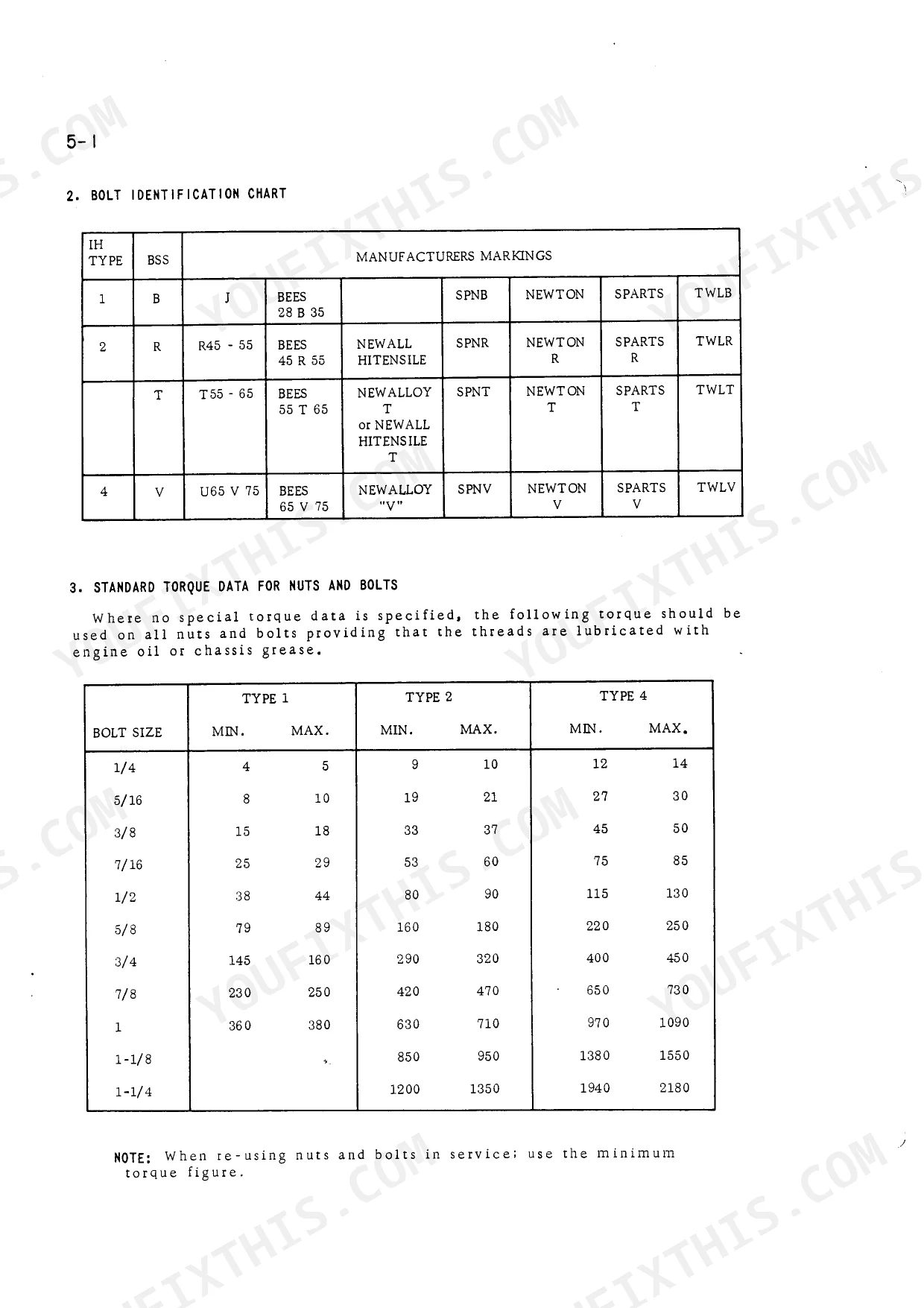
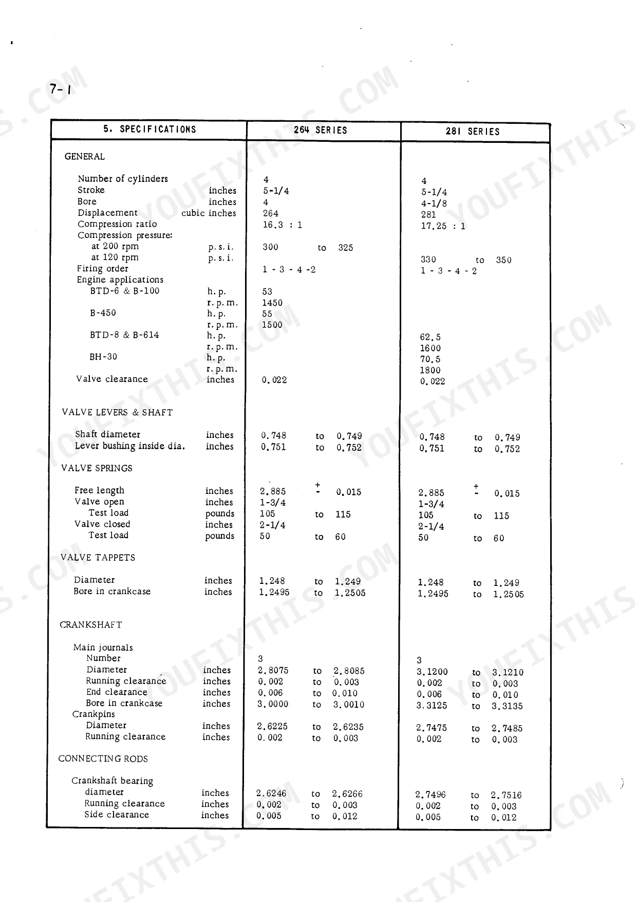
| General | 9-18 | Specifications, Inspection & Repair, Service Tools, Bolt Identification Chart, Standard Torque Data, Special Torque Loadings |
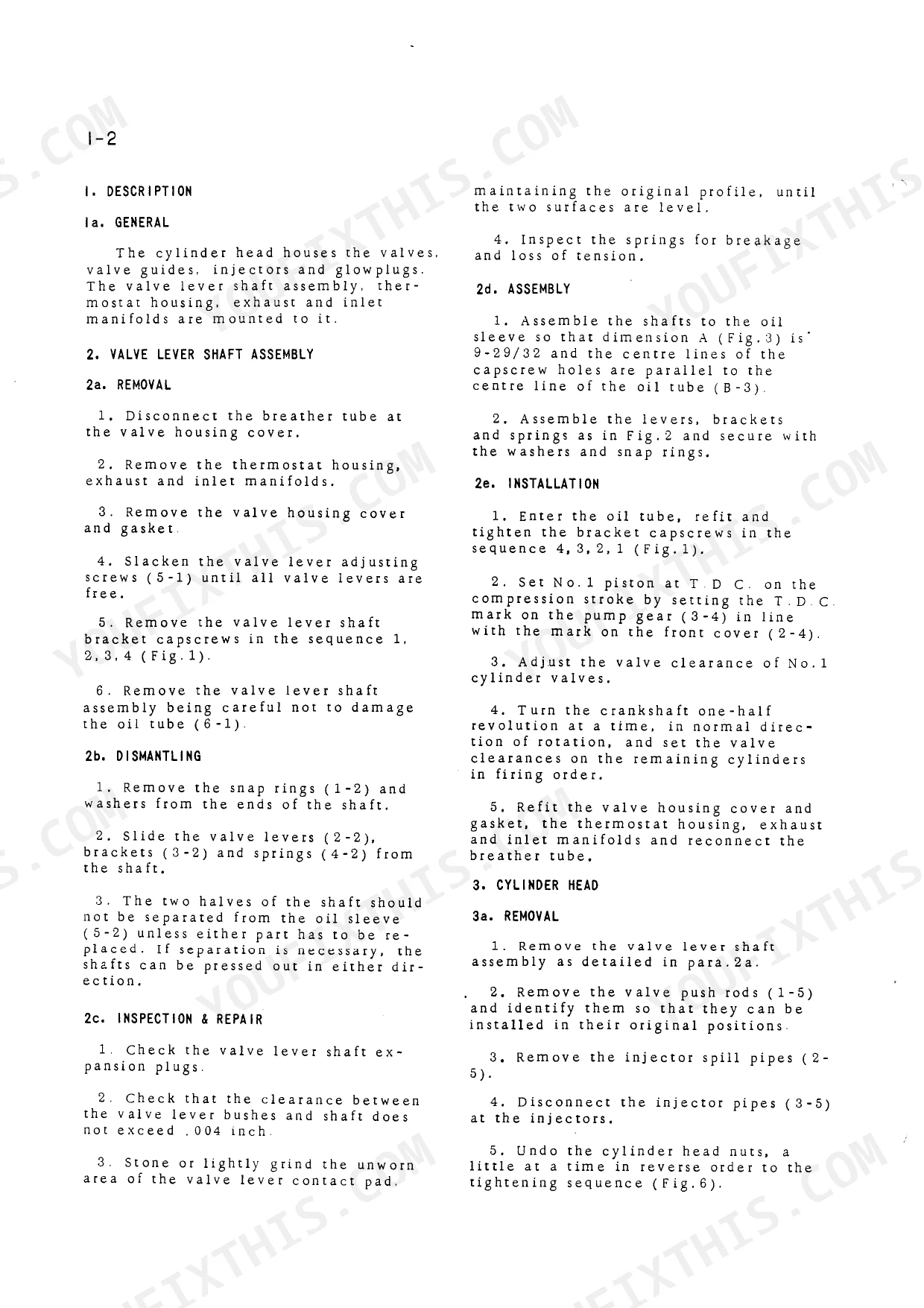
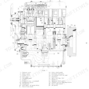
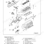
| Manifolds, Cylinders Head and Valves | 19-24 | Valve Lever Shaft Assembly, Cylinder Head, Valves, Valve Guides, Injectors, Manifolds |
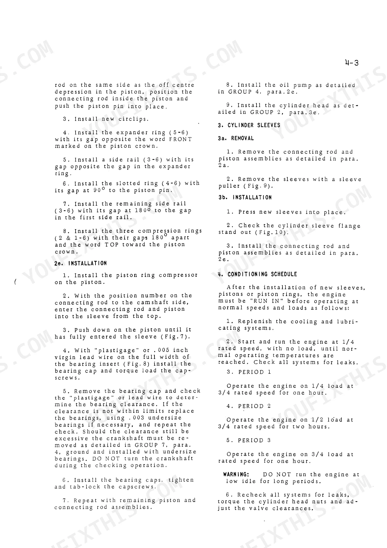
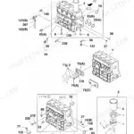
| Connecting Rods, Pistons and Cylinder Sleeves | 25-30 | Connecting Rod and Piston Assembly, Pistons, Cylinder Sleeves, Piston Rings, Piston Pins, Conditioning Schedule |
| Lubricating System | 31-38 | Oil Pump, Oil Filter, Single Stage Pump, Two Stage Pump, Regulating Valve, Oil Delivery Pipe |
| Water Pump and Thermostat | 39-44 | Water Pump, Thermostat, Fan, Packing Gland, Impellor, Bearings |
| Timing Gear Train, Front Cover and Camshaft | 45-52 | Timing Gear Train, Front Cover, Camshaft, Fuel Injection Pump Timing, Crankshaft Pinion, Idler Gear |
| Crankshaft, Main Bearings and Flywheel | 53-62 | Crankshaft, Main Bearings, Flywheel, Rear Engine Support, Crankshaft Bearing Cap Replacement, Crankshaft Gear |
Quick Reference Specifications
| Specification | Value | Page |
|---|---|---|
| Piston rings - Compression - Ring gap - Top | 0.016 to 0.026 inches | p. 17 |
| Piston rings - Compression - Ring gap - Second | 0.013 to 0.023 inches | p. 17 |
| Cylinder head nuts torque | 110 to 115 Lb. ft. | p. 15 |
| Crankshaft Main Journal Running Clearance | 0.002 to 0.003 inches | p. 16 |
| Piston Ring Gap (Top) | 0.016 to 0.026 inches | p. 17 |
| Timing Gear Backlash | 0.003 to 0.006 inches | p. 18 |
| Oil Pump Gears to Housing Clearance | 0.007 to 0.0085 inches | p. 18 |
| Thermostat Operating Range | 176 to 199 °F | p. 18 |
International BD-264, BD-281 Common Problems This Manual Covers
International BD-264 and BD-281 engine won't start or has intermittent starting after normal operation
Check fuel injection pump timing per the procedure on page 45. Verify timing gear backlash is within 0.003 to 0.006 inches (page 18). Inspect the advance mechanism canister for leaks or seal failure. If timing deviation exceeds 5°, remove the injection pump, reset timing to specification, and reinstall before attempting restart.
Manual Section: Timing Gear Train, Front Cover and Camshaft p. 45Engine loses power under load or runs rough with visible exhaust smoke
Inspect the intake manifold for restriction, then check injectors per the service procedure on page 20. Verify injector timing; any deviation greater than 5° will produce rough running under load. Torque cylinder head nuts to 110 to 115 Lb. ft. (page 15) if head has been disturbed. Clean all injector passages before reassembly.
Manual Section: Manifolds, Cylinders Head and Valves p. 20Excessive oil consumption with visible leakage pooling under the four-cylinder engine block
Remove and inspect piston rings per the procedure on page 29. Measure top ring gap in the bore; spec is 0.016 to 0.026 inches (page 17). Check ring clearance in groove: 0.0035 to 0.0055 inches. Replace the full ring set if any measurement is out of spec. Inspect cylinder sleeve bores for scoring before reassembly.
Manual Section: Connecting Rods, Pistons and Cylinder Sleeves p. 29Oil pressure drops below threshold at idle speed or under sustained load
Remove the oil pump and measure gear-to-housing clearance; specification is 0.007 to 0.0085 inches. Inspect the regulating valve for wear and check the oil delivery pipe for blockage. Disassemble and clean the oil filter assembly. Replace pump gears if clearance falls outside spec, then verify pressure returns to normal before closing up.
Manual Section: Lubricating System p. 31Engine overheats repeatedly with coolant temperature climbing above normal operating range
Test the thermostat in hot water; it must begin opening between 176 and 199°F (page 18). Remove and inspect the water pump impeller and bearings per page 39. Check the packing gland for leakage and adjust as needed. Flush the cooling passages, confirm fan blade condition, and verify belt tension before returning the engine to service.
Manual Section: Water Pump and Thermostat p. 39Frequently Asked Questions
What are the torque specs for the cylinder head, crankshaft, and rod bolts?
For the engines, the special torque loadings are as follows: Cylinder head nuts should be torqued to 110 to 115 Lb. ft., Main bearing capscrews to 150 to 170 Lb. ft., and Connecting rod capscrews to 55 to 60 Lb. ft. These specifications are crucial for proper assembly and engine operation. p. 15
How quickly can I access this International BD-264, BD-281 manual after buying?
A 62-page Service Manual in searchable PDF format (3 MB), available the moment you complete checkout. View on computer, tablet, or phone, with no shipping wait.
Can I print specific sections of this International BD-264, BD-281 manual?
No restrictions at all. Print individual pages, full chapters, or the entire manual. The PDF is completely unlocked.
Reviews
There are no reviews yet.