


Part of the John Deere Repair Manuals.
This is the complete John Deere factory technical manual (TM900719, March 2012) for the 5038D, 5042D, 5045D, 5047D and 5050D India-market utility tractors. Across 1,261 pages it covers everything a dealer technician works through: pulling and rebuilding the 3000-series engine, servicing the fuel injection and air systems, tracing the full electrical system with wiring schematics, repairing the AA transmission and PTO clutch assemblies for both 2WD and 4WD variants, servicing the JD Rockshaft hydraulic system, and adjusting the front axle and 3-point hitch. Every repair section is paired with an operation, tests and adjustments section so you can diagnose a fault before you pull anything apart.
What's Inside This John Deere 5038D, 5042D, 5045D, 5047D, 5050D Repair Manual
| System | Pages | Key Topics |
|---|---|---|
| General Information | Safety, General Specifications, Fuel and Lubricants, Serial Number Locations, Features and Accessories | |
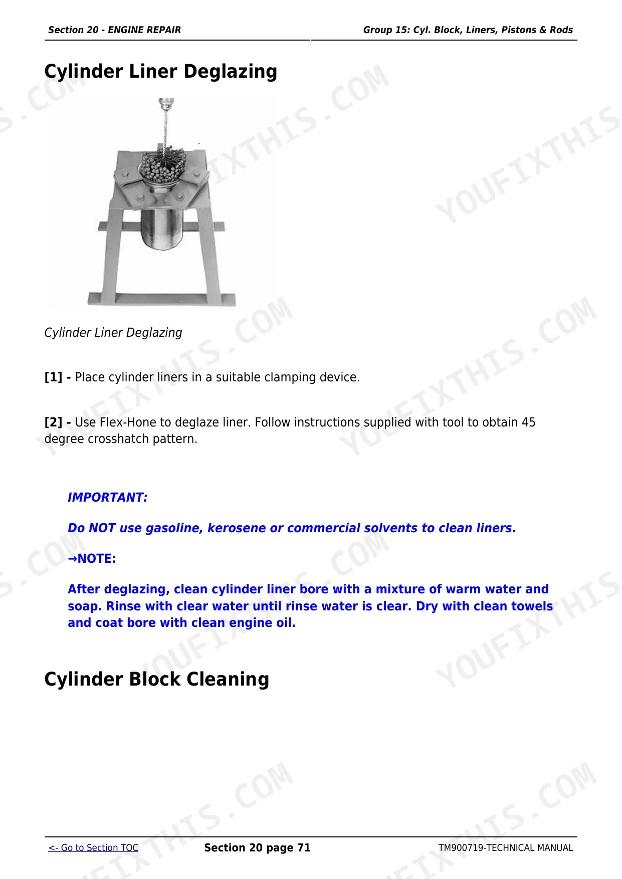
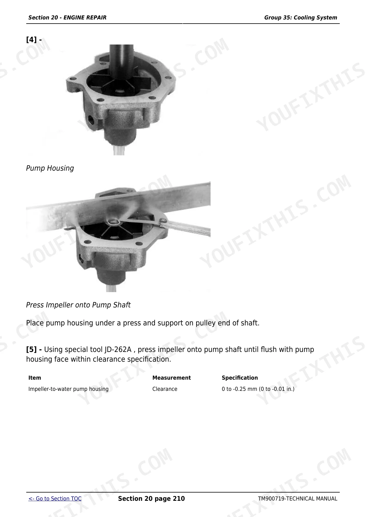
| Engine Repair | Engine, Cylinder Head and Valves, Block/Liners/Pistons and Rods, Crankshaft/Main Bearings and Flywheel, Camshaft and Timing Gear Train, Lubrication System, Cooling System | |
| Fuel and Air Repair | Fuel System, Air Intake and Exhaust System, Speed Control Linkage | |
| Electrical Repair | Battery/Starter and Alternator, Electrical System Components, Wiring Harness | |
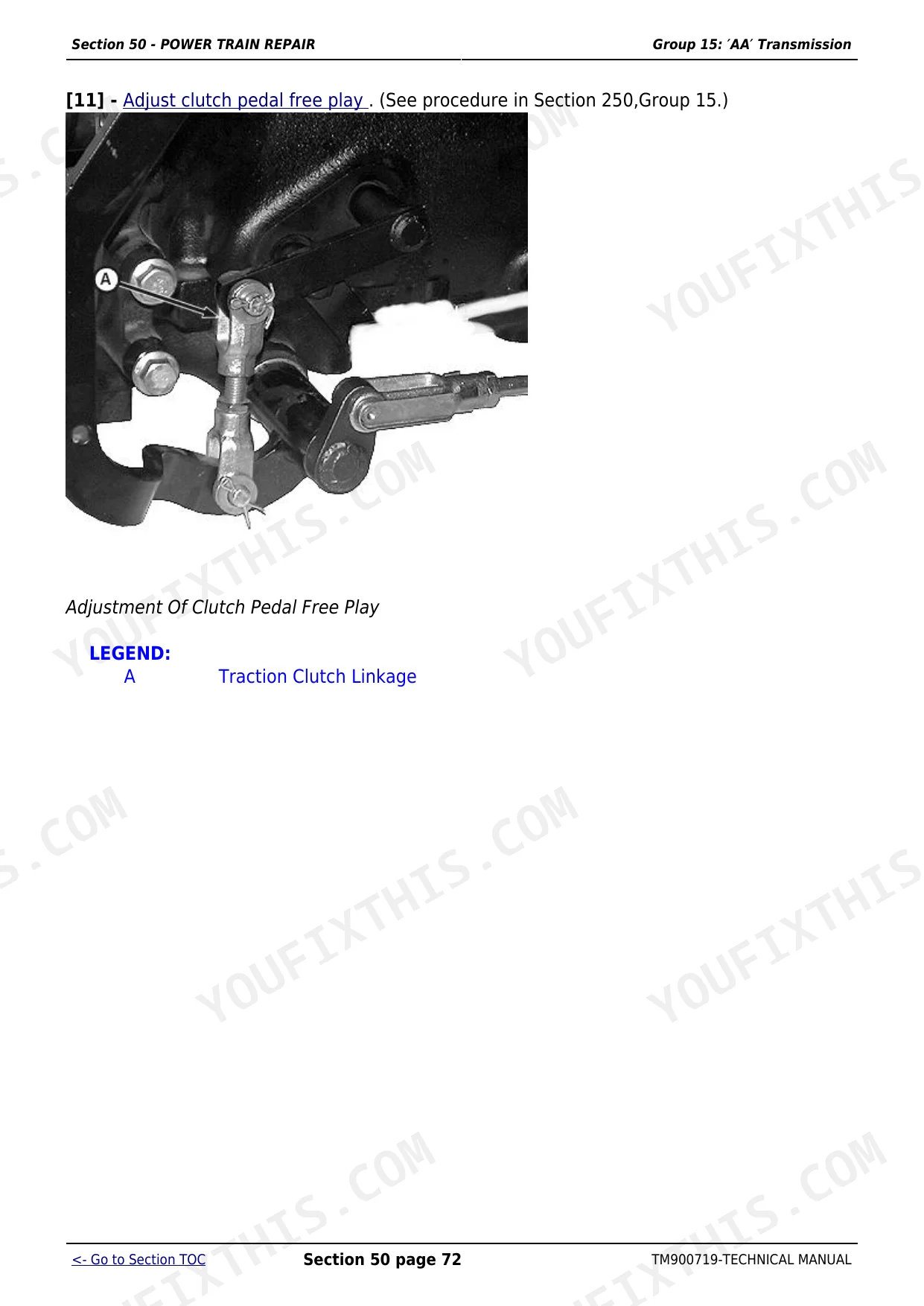
| Power Train Repair | Clutch Housing, Clutch Assembly, Aa Transmission, Mechanical Front Wheel Drive, Rear PTO Dual Clutch, Rear PTO Single Clutch, Differential, Final Drives | |
| Steering and Brake Repair | Steering Gear Box, Tie Rod Ends and Adjustment, Steering Cylinder, Brake Pedal Adjustment, Brake Disc and Caliper, Parking Brake, Master Cylinder, Toe-In Adjustment | |
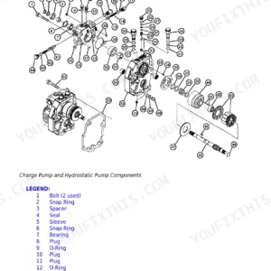
| Hydraulic Repair | Hydraulic Pump and Filter, Jd Rockshaft | |
| Miscellaneous Repair | Front Axle, Wheels, 3-Point Hitch | |
| Operator Station Repair | Seat and Support, Operator Platform, Fenders, ROPS (Roll Over Protective Structure) | |
| Operational Checkout Procedures | Engine Warm-Up and Instrument Check, Hydraulic Function Test, Brake and Steering Verification, PTO Engagement, 3-Point Hitch Check, Transmission and Differential Operation | |
| Engine Operation, Tests and Adjustments | Component Location, Theory of Operation, Diagnosis, Tests and Adjustments | |
| Fuel and Air Operation, Tests and Adjustments | Injection Pump Timing, Fuel Injection Pressure Test, Nozzle Testing and Adjustment, Air Intake Restriction Check, Throttle Linkage, Governor Adjustment, Fuel Filter | |
| Electrical System Operation, Tests and Adjustments | Component Location, Theory of Operation, Wiring Schematics, Diagnosis, Test and Adjust | |
| Power Train Operation, Tests and Adjustments | Component Location - Aa Power Train, Theory of Operation - Aa Transmission, Diagnosis, Tests and Adjustments | |
| Steering and Brake Operation, Tests and Adjustments | Component Location, Steering Circuit Theory, Brake System Theory, Steering Adjustment Procedure, Brake Adjustment and Bleeding, Parking Brake Test | |
| Hydraulic System Operation, Tests and Adjustments | Component Location, Theory of Operation, Diagnosis, Hydraulic Tests, Adjustments - Jd Rockshaft, Hydraulic Schematics |
Quick Reference Specifications
| Specification | Value | Page |
|---|---|---|
| 5038D, 5042D, 5045D, 5050D | ||
| Fuel Tank Capacity | 60 L (15.8 gal) | |
| 5045D 4WD | ||
| Max PTO Power (5045D 4WD) | 28.1 kW (38.2 HP) | |
| All models | ||
| Transmission Oil Capacity (manual steering) | 33 L | |
| Engine Cooling Freeze Protection | -37 deg C (-34 deg F) | |
| Engine to Front Support - Top Cap Screws Torque | 290 N.m (214 lb-ft) | |
| Engine to Front Support Nut Torque | 165 N.m (111 lb-ft) | |
| Cylinder Head Thickness (new) | 104.87-105.13 mm (4.129-4.139 in.) | |
| Max Cylinder Head Material Removal | 0.76 mm (0.030 in.) | |
| Cylinder Head Sealing Surface Flatness Limit | 0.08 mm (0.003 in.) | |
| Intake Valve Stem Diameter (standard) | 7.864-7.884 mm (0.3096-0.3104 in.) | |
| Exhaust Valve Stem Diameter (standard) | 7.848-7.874 mm (0.3090-0.3100 in.) | |
| Valve Stem to Guide Bore Clearance (new parts) | 0.05-0.10 mm (0.002-0.004 in.) | |
| Power steering models | ||
| Transmission Oil Capacity (power steering) | 35 L | |
| Engines with 142-tooth flywheel ring gear | ||
| Flywheel Housing Guide Bore Diameter (142-tooth ring gear) | 26.5 mm (1.04 in.) | |
John Deere 5038D, 5042D, 5045D, 5047D, 5050D Common Problems This Manual Covers
JD Rockshaft drops under load or hydraulic lift is slow and weak
Start by replacing the hydraulic filter and checking the fluid level; contaminated or low fluid is the most common cause of weak lift on these tractors. If lift remains slow, move to the Hydraulic Repair section to remove and test the hydraulic pump for worn seals and check the rockshaft control valve for internal bypass. The Hydraulic System Tests and Adjustments section gives the minimum test pressures to confirm whether the pump, valve or cylinder is at fault before pulling the pump for rebuild.
Manual Section: Hydraulic RepairEngine overheats under field load, temperature gauge climbs to red
First clean the radiator fins, which clog quickly in dusty field conditions on these India-market tractors, and verify the coolant level. If overheating continues, test the thermostat and water pump as described in the Cooling System group of the Engine Repair section. The Engine Operation, Tests and Adjustments section provides the coolant temperature test procedure so you can confirm whether the fault is a stuck thermostat, a failing water pump, or a restricted radiator before replacing components.
Manual Section: Engine RepairPTO slips under load or fails to engage when connecting heavy implements
PTO slip or no-engagement on the 5D-series usually means worn clutch plates in the Rear PTO Dual or Single Clutch assembly. The Power Train Repair section covers both PTO clutch configurations: removal, inspection, plate measurement against wear limits, and reassembly. The Power Train Tests and Adjustments section gives the clutch engagement pressure specs so you can verify hydraulic pressure to the PTO before deciding whether to rebuild the clutch pack or adjust the control linkage.
Manual Section: Power Train RepairFront axle vibration or binding on 4WD models, especially under full steering lock
Vibration under steering lock on the 4WD models is most often a worn or failed front axle universal joint. The Miscellaneous Repair section covers front axle disassembly, U-joint inspection and replacement, and differential bearing checks. Inspect the U-joints for play before assuming the differential is at fault, as worn joints are a known wear item on these tractors and are cheap to replace compared to differential bearings.
Manual Section: Miscellaneous RepairFrequently Asked Questions
What engine is in the John Deere 5038D, 5042D, 5045D, 5047D and 5050D tractors?
All five models run a John Deere 3000-series diesel engine. The Engine Repair section covers complete teardown and rebuild procedures, including cylinder head and valve service, piston and liner replacement, crankshaft and timing gear work, and the lubrication and cooling systems, with the torque values and wear limits you need to bring an engine back to spec.
Why does the JD Rockshaft drop or fail to hold position under load?
A slow-dropping or weak rockshaft almost always points to worn hydraulic pump seals, a clogged hydraulic filter, or internal leakage past the rockshaft control valve. The Hydraulic Repair section covers removing and rebuilding the hydraulic pump and filter assembly, and the Hydraulic System Operation, Tests and Adjustments section gives the specific test pressures so you can confirm whether the fault is in the pump, the valve, or the cylinder before replacing parts.
Does this manual cover both 2WD and 4WD power train repair?
Yes. The Power Train Repair section covers the AA transmission, clutch housing and assembly, rear PTO dual and single clutch, differential and final drives for all models, plus a dedicated Mechanical Front Wheel Drive group covering the 4WD axle. The paired Power Train Operation, Tests and Adjustments section provides the diagnosis flow and pressure test specs for both drivetrains.
What are the torque specs for the engine mounting and head bolts on these tractors?
The General Information and Engine Repair sections list the key assembly values. Engine to front support top cap screws torque to 290 N.m (214 lb-ft); the front support nuts torque to 165 N.m (111 lb-ft). Cylinder head and other fastener torques are listed at the beginning of each service group in the Engine Repair section.
Does the manual include wiring diagrams for diagnosing electrical faults?
Yes. The Electrical Repair section covers battery, starter, alternator and the wiring harness, and the Electrical System Operation, Tests and Adjustments section includes full wiring schematics along with component location diagrams, theory of operation and a diagnosis and test procedure flow to trace intermittent faults from the alternator charge circuit through to the instrument panel.
What format is this John Deere 5038D, 5042D, 5045D, 5047D, 5050D manual in?
This is a 1261-page searchable PDF (47 MB) ready for immediate download. Works on any device, so pull it up on your phone while you're under the hood. No shipping, no waiting.
Is this John Deere 5038D, 5042D, 5045D, 5047D, 5050D Repair printable?
Yes, print as many copies as you want, and there are no restrictions. Many mechanics print the section they need and bring it to the shop floor.


Reviews
There are no reviews yet.