


![John Deere 5425 5625 5725 Narrow / Orchard / HC Operation And Test Manual [Tractors]](https://youfixthis.com/wp-content/uploads/2012/02/Manual_Download-300x300.jpg)

Part of the John Deere Repair Manuals.
This is the complete John Deere factory operation and test manual (TM1654) for the 7210, 7410 and 7510 tractors. Across 1,238 pages it covers every diagnostic procedure on these machines: reading and clearing controller fault codes, performing the operational checkout sequence, testing hydraulic pressures, tracing wiring schematics and calibrating transmission and drive systems. It is organized by system section and gives the exact test steps, pressure values and calibration tolerances a dealer tech uses before condemning a component.
What's Inside This John Deere 7210, 7410, 7510 Manual
| System | Pages | Key Topics |
|---|---|---|
| Safety Information | Safety Procedures, Operational Hazard Warnings | |
| General Information | Operational Checkout, General Reference Information, Test Equipment Calibration | |
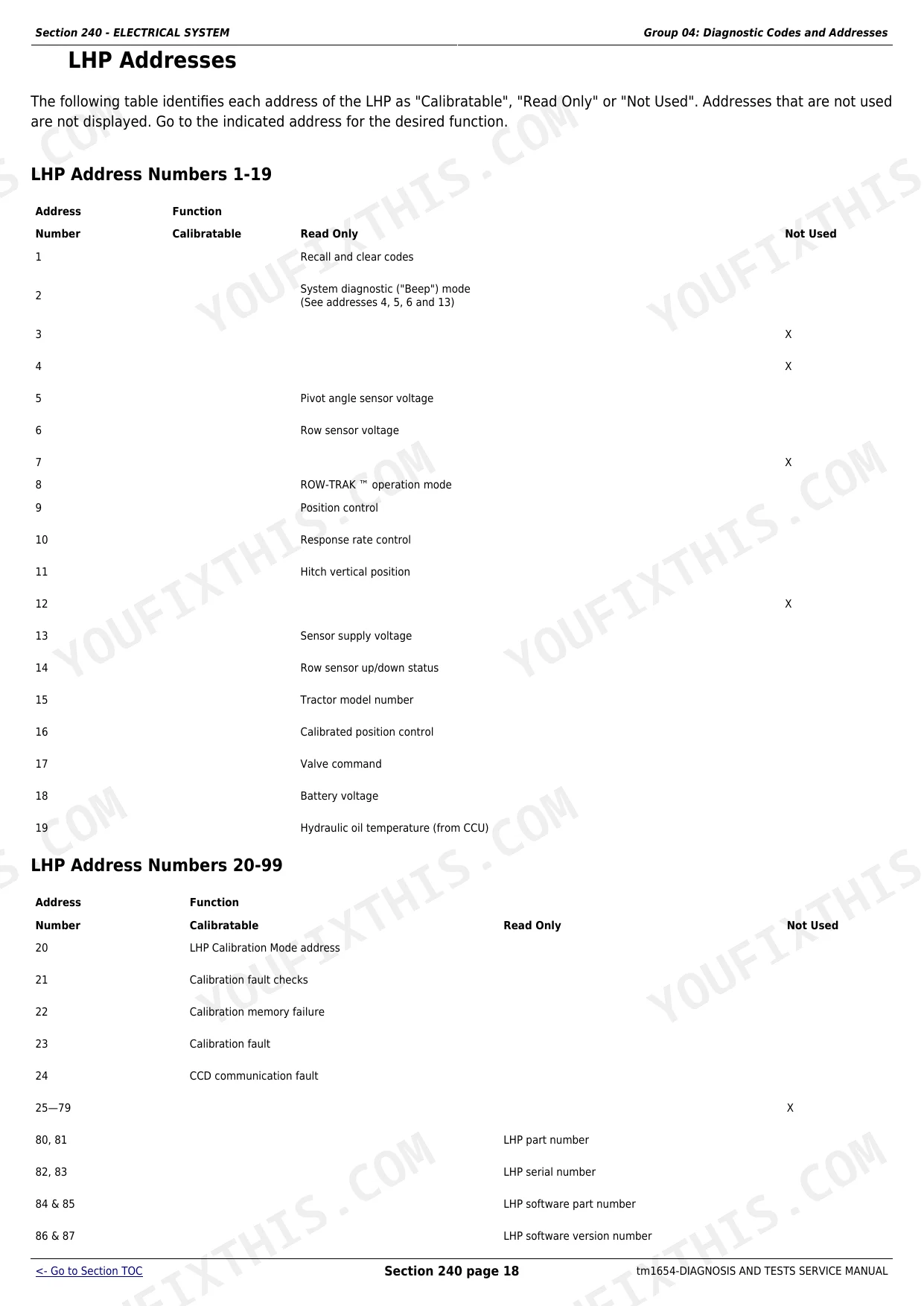
| Diagnostic Trouble Codes | Ccu Code Diagnostics, Hcu Code Diagnostics, Lhp Code Diagnostics, Rcu Code Diagnostics | |
| Observable Symptoms | Brake Symptoms, Operator Station Symptoms, Hydraulic Symptoms | |
| Engine | Engine General Information, Power Output Specs, Test Procedures | |
| Fuel, Air Intake and Engine Cooling | Fuel System Theory of Operation, Air Intake and Cooling Diagnostics | |
| Electrical System | Diagnostic Codes and Addresses, System Functional Schematics (Cab and Oos), Wiring Harnesses, Starting and Charging Diagnostics, Sub-System Diagnostics | |
| Transmissions | SyncroPlus and PowrQuad Transmission Test Procedures, Calibration, Pressure Checks | |
| Drive Systems | MFWD Axle Diagnostics, Drive System Test Procedures | |
| Steering and Brakes | Steering System Tests, Brake Adjustment and Diagnostics | |
| Hydraulic System | Hydraulic Pressure Testing, Pump Flow Tests, Hitch Diagnostics | |
| Operator Station | Instrument Cluster Diagnostics, Controls and Indicator Tests | |
| Dealer Fabricated Tools | Instructions for Fabricating Special Test Tools |
Quick Reference Specifications
| Specification | Value | Page |
|---|---|---|
| 7210 | ||
| PTO Power | 70.9 kW (95 hp) at 2100 rpm | |
| 7410 | ||
| PTO Power | 78.4 kW (105 hp) at 2100 rpm | |
| 7510 | ||
| PTO Power | 85.6 kW (115 hp) at 2100 rpm | |
| All models | ||
| Engine Displacement | 6.8 L (414 in.3), 6-cylinder | |
| Bore and Stroke | 106.5 x 127.0 mm (4.19 x 5.00 in.) | |
| Compression Ratio | 17.0:1 | |
| Slow Idle Speed | 850 +/- 50 rpm | |
| Valve Clearance - Intake | 0.35 mm (0.014 in.) | |
| Valve Clearance - Exhaust | 0.45 mm (0.018 in.) | |
| Crankcase Capacity with Filter | 19 L (20 qt) | |
| Cooling System Capacity | 21 L (22 qt) | |
| Hydraulic System Maximum Pressure | 20 000 kPa (200 bar / 2900 psi) | |
| Firing Order | 1-5-3-6-2-4 | |
| Base, Hi-Crop and High Clearance | ||
| Fuel Tank Capacity | 190 L (50 gal) | |
John Deere 7210, 7410, 7510 Common Problems This Manual Covers
MFWD axle fails prematurely under heavy loader or field load
Diagnose the axle before replacement: Section 256 covers the MFWD drive system test sequence including clutch element pressure and solenoid voltage checks. If the clutch element pressure is within spec but the axle housing shows wear, the factory standard axle is a known weak point on this series and owners commonly upgrade to the HD Loader Approved 1100 Series axle as a permanent fix. Do not assume it is the axle until you have confirmed the clutch and solenoid are not the cause.
Manual Section: Drive SystemsTransmission loses power or disengages under load
Power drop under load on the SyncroPlus or PowrQuad is most often a transmission cooler flow restriction or internal pressure loss from a clutch element leak. Section 250 covers the cooler flow check and clutch pressure tests. Start with the cooler - a blocked cooler starves the clutch elements of lube flow and causes them to slip and glaze before eventually failing. Replace the cooler flow valve if it does not meet the specified flow rate, then retest clutch pressure before opening the transmission.
Manual Section: TransmissionsController fault code appears in cab display with no clear cause
Work through the code from Section 211 before touching any components. Each CCU, HCU, LHP and RCU code entry includes a probable cause list ranked by likelihood and the specific electrical tests (voltage, resistance, continuity) to confirm or rule out each cause. Skipping straight to parts replacement on controller codes is expensive - wiring faults, corroded connectors and failed sensors are far more common than controller failures on this series.
Manual Section: Electrical SystemHitch will not lift to full height or lifts slowly under load
Slow or incomplete hitch lift on the 7210 through 7510 is usually a pump flow issue or a worn relief valve. The hitch lift capacity should be 3360 kg (7400 lb) at rated system pressure of 20 000 kPa (2900 psi). Section 270 covers testing pump output with a calibrated flow meter and checking relief valve crack pressure. If pump flow is low, inspect the pump for worn gears before condemning it - a clogged inlet screen can cause the same symptoms and takes five minutes to clear.
Manual Section: Hydraulic SystemFrequently Asked Questions
How do I read and clear diagnostic trouble codes on the John Deere 7210, 7410 and 7510?
The manual covers CCU, HCU, LHP and RCU controller codes in Section 211. To read active codes you use the cab instrument display or a Service Advisor scan tool; the manual lists each code with a description, probable cause and the exact test sequence to isolate the fault before clearing it. Clearing without diagnosing first is not recommended - the code will return if the root cause is not fixed.
What causes the MFWD to stop engaging or fail on these tractors?
MFWD engagement problems on the 7210 through 7510 series are usually traced to the front axle clutch element, the MFWD engagement solenoid, or a wiring fault in the drive circuit. Section 256 covers the drive system diagnostic procedure - check the solenoid output voltage and clutch pressure before pulling the axle. Many owners who replaced the standard axle upgraded to the HD Loader Approved 1100 Series unit to prevent recurrence under heavy loader work.
How do I test hydraulic system pressure on the 7210, 7410 or 7510?
Section 270 gives the hydraulic test procedures. Maximum system pressure is 20 000 kPa (2900 psi). You install a calibrated gauge at the test port specified in the manual and run the engine at rated speed to verify pump output. If pressure is low, the manual walks through testing the pump, the relief valve and the priority valve before you decide which component to replace.
The differential lock indicator flashes but the lock does not engage - what should I check?
A flashing differential lock light with no lock function points to three common faults covered in the electrical diagnostics section: a blown F1 fuse in the front electronics circuit, a failed differential lock actuator, or a broken or corroded wire in the actuator harness. Check the fuse first - it is the two-minute fix. If the fuse is good, test the actuator resistance and then trace the harness for chafed insulation near the rear axle housing.
What transmission options are covered in this manual and how do I check fluid capacity?
The manual covers both the SyncroPlus (12 forward/4 reverse) and PowrQuad (16 or 20 forward/12 reverse) transmissions in Section 250. Fluid capacity varies by configuration: SyncroPlus base is 57 L (15 gal), rising to 68 L (18 gal) with MFWD and creeper. PowrQuad capacities match the same pattern. Always check the actual fill level at the sight glass with the tractor on level ground and the engine off after fluid has settled.
Is this John Deere 7210, 7410, 7510 Operation and Test a digital download?
Instant PDF download (53 MB). You get the full 1238-page searchable Operation and Test immediately after payment. Open it on your laptop, tablet, or phone right in the shop.
Is this John Deere 7210, 7410, 7510 Operation and Test printable?
Absolutely. No DRM or copy protection. Print the whole manual or just the pages you need. Any home or office printer works.


Reviews
There are no reviews yet.