

Part of the John Deere Repair Manuals.
Pulling the engine gear case to reach the separator drive wet clutch is the job most owners hand to the dealer. TM4697 covers the gear case removal and installation and the clutch itself. It also gives the engine-to-gear case cap screw torque of 340 N·m (250 lb-ft).
The same book covers the hydrostatic system, cam lobe motors, transmission and final drives. It continues through the feeder house and reverser, threshing cylinder, straw walkers, cleaning shoe, grain tank augers and the R134a air conditioning. It applies to the 9540, 9560, 9580, 9640, 9660 and 9680 WTS and CWS combines, European Version.
Every dry day the combine sits in the shed is crop still standing in the field. Print the group you need and take it to the bench. Greasy pages are fine if the machine is threshing again.
What's Inside This John Deere 9540-9680 WTS/CWS Repair Manual
| System | Pages | Key Topics |
|---|---|---|
| General, Safety and Identification | 1-20 | Safety Information, Combine Type Plate, Engine Serial Number, Hydrostatic Drive Pump and Transmission Serial Numbers |
| Specifications, Tune-Up and Lubricants | 21-52 | Operating Speeds, Specifications for 9540 and 9560-9680, Dimensions, Metric Bolt and Cap Screw Torque Values, Tune-Up Checks, Diesel Fuel and Gear Case Oils |
| Engine Removal and Cooling System | 53-90 | Remove and Install Engine, Engine Oil Pan Access, Rotary Screen Drive, Radiator Removal and Test, Water Pump |
| Fuel and Air System | 91-120 | Turbocharger, Charge Air Cooler, Air Cleaner Filters, Fuel Tank and Strainer, Bleeding the Fuel System |
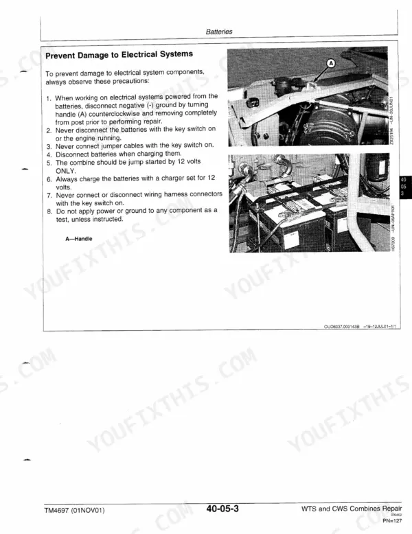
| Batteries, Connectors and Wiring Harnesses | 121-170 | Electrolyte Specific Gravity, Charging Batteries, Pull-Type and Blade-Type Connector Repair, Wiring Harness Routing, Fuses, Circuit Breakers and Relays, Lighting |
| Electrical Components | 171-244 | Overhead Console, Header Control Module, Neutral Safety Switch, Grain Tank and Fuel Level Sensors, Wiper Motor, Alternator, Starting Motor, Mass-Flow and Moisture Sensors |
| Transmission, Differential and Final Drives | 245-298 | Transmission Lube Pump, Remove and Assemble Transmission, Gearshift Linkage, Final Drive Disassembly, Spindle Bearing Adjustment |
| Hydrostatic System | 299-378 | Flushing the Hydrostatic System, Hydrostatic Motor Removal and Disassembly, Cylinder Block Inspection |
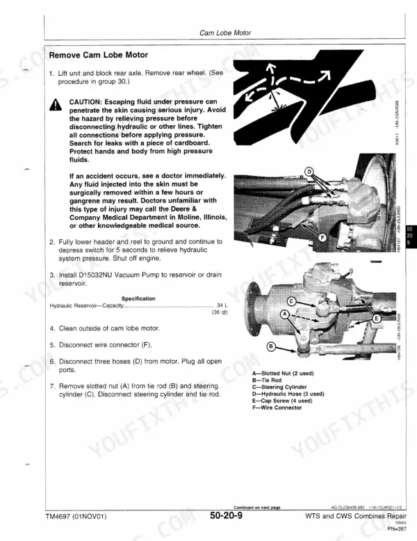
| Cam Lobe Motor, Tires and Wheels | 379-446 | Flushing Cam Lobe Motors, Cam Lobe Motor Control Valve, Axle Bearings and Seals, Drive Wheel Bolt Torque, Rear Wheel Weights, Rocker Assemblies |
| Steering, Brakes and Trailer Hitch | 447-532 | Steering Valve, Steering Cylinder Repair, Toe-In Adjustment, Brake Drum and Heavy-Duty Brakes, Master Cylinder, Park Brake Pedal, Hitch Removal |
| Hydraulic Repair | 533-604 | Reservoir and System Flushing, Main Hydraulic Pump, Valve Stack, Feeder House Reverser Valve, Header Lift and Unloading Auger Swing Cylinders, Chaff Spreader Motor, Accumulator Precharge |
| Separator Shell | 605-612 | Gull Wing Doors, Composite Panel Repair |
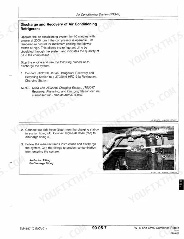
| Air Conditioning and Heating | 613-658 | Compressor, Volumetric Efficiency Test, Clutch Hub Clearance, Purging the System, Receiver-Dryer, Blower Motor, Heater Control Valve |
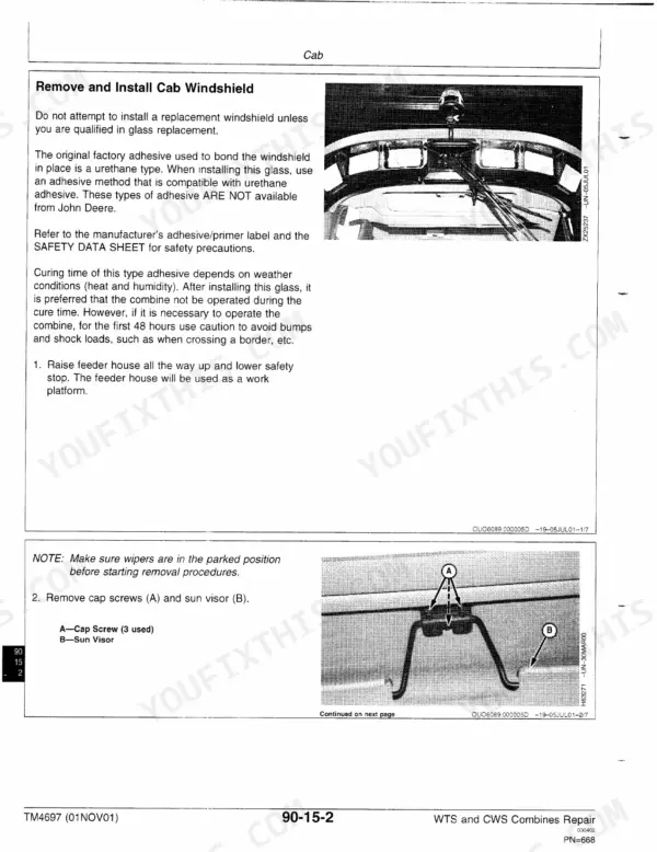
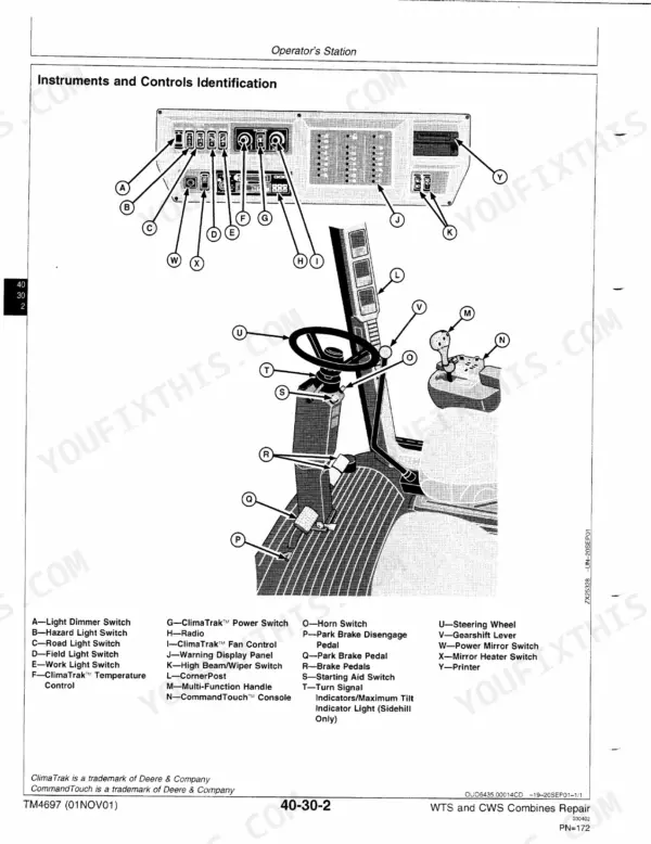
| Cab | 659-698 | Cab Windshield, Remove and Install Cab, Operator's Seat |
| Feeder House Conveyor and Top Shaft | 699-730 | Remove and Install Feeder House, Conveyor Chain Adjustment, Sub-Floor Assembly, Top Shaft Slip Clutch Adjustment |
| Feeder House Drives, Reverser and Tilt Frame | 731-778 | Feeder House Countershaft and Tensioner, Reverser Gear Case, Lower Shaft, Tilt Cylinder Hoses, Tilt Frame and Beam, Fore-Aft Turnbuckles |
| Threshing Cylinder and Cylinder Drives | 779-882 | Rasp Bars, Threshing Cylinder Removal, Concave Wear Check, Second Cylinder, Cylinder Drive Runout, Dual Range Cylinder Drive, Intermediate Cylinder Drive |
| Straw Walkers, Chopper and Spreaders | 883-932 | Walker Timing, Straw Walker Bearings, Rear Crankshaft, Walker Gear Case, Straw Chopper Blades, Rotor Bearing, Chaff Spreader |
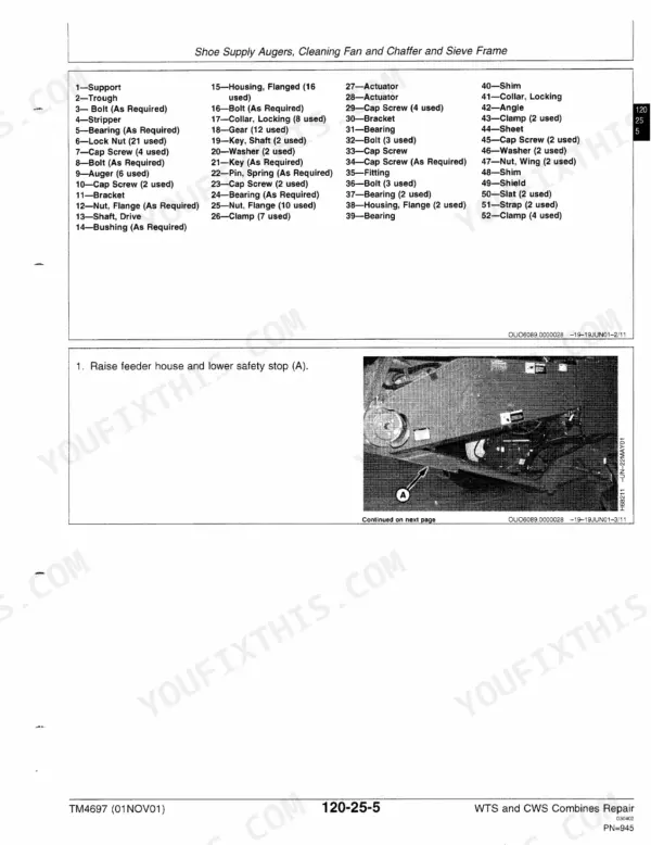
| Cleaning Shoe, Tailings and Primary Countershaft | 933-1028 | Shoe Supply Augers, Separator Drive Jackshaft, Cleaning Fan, Chaffers and Sieve Frames, Tailings Elevator, Primary Countershaft Gear Case, Header Electromagnetic Clutch |
| Grain Tank and Unloading System | 1029-1128 | Grain Tank Cross Augers, Unloading Auger Drive Countershaft, Vertical Auger Lower Gear Case, Horizontal Unloading Auger Gear Case, Clean Grain Elevator, Grain Tank Extensions |
| Engine Gear Case and Control Valve | 1129-1176 | Remove and Install Engine Gear Case, Separator Drive Wet Clutch, Hydrostatic Gear Set |
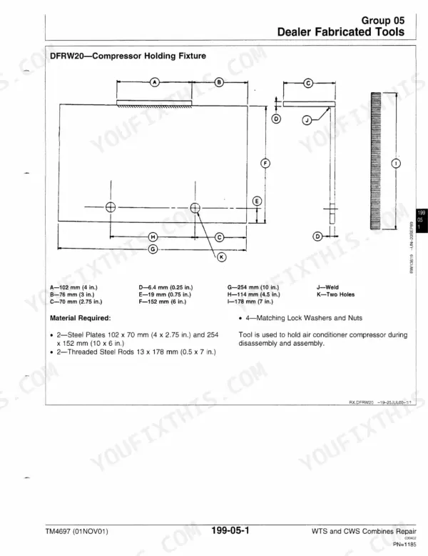
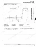
| Dealer Fabricated Tools and Index | 1177-1204 | Compressor Holding Fixture, Alphabetical Index |
Quick Reference Specifications
| Specification | Value | Page |
|---|---|---|
| Technical manual | TM4697 (01NOV01), WTS and CWS Combines Repair | p. 26 |
| Diagnosis and tests manual (separate) | TM4698 | p. 1 |
| Engine, 9540 | John Deere 6068AZ, 6.8 L (414 cu. in.), 152 kW (206 hp) | p. 26 |
| Engine, 9560-9680 | John Deere 6081HZ, 8.1 L (499 cu. in.) | p. 27 |
| Engine power, 9560 | 175 kW (238 hp), 200 kW (272 hp) boost | p. 27 |
| Engine power, 9580 and 9640 | 200 kW (272 hp), 225 kW (306 hp) boost | p. 27 |
| Engine power, 9660 | 222 kW (302 hp), 247 kW (336 hp) boost | p. 27 |
| Engine power, 9680 | 247 kW (336 hp), 272 kW (370 hp) boost | p. 27 |
| Rated engine speed | 9540: 2300 rpm; 9560-9680: 2100 rpm | p. 22 |
| Slow / fast idle | 9540: 1300 / 2550 rpm; 9560-9680: 1200 / 2340 rpm | p. 22 |
| Fuel tank | 700 L (185 gal.) | p. 28 |
| Engine crankcase with filter, 9540 | 18.9 L (20 qt) | p. 26 |
| Engine crankcase with filter, 9560-9680 | 28.5 L (30 qt) | p. 28 |
| Cooling system with heater, 9540 | 36 L (38 qt) | p. 26 |
| Hydraulic/hydrostatic reservoir | 34 L (36 qt) | p. 28 |
| Transmission | 9.6 L (10 qt) | p. 28 |
| Final drives (each) | 8.5 L (9 qt) | p. 28 |
| Grain tank capacity, 9560-9680 | 9560: 7,500 L (213 bu.); 9580 and 9640: 8,000 L (227 bu.); 9660: 9,000 L (255 bu.); 9680: 11,000 L (312 bu.) | p. 27 |
| Engine-to-gear case cap screws | 340 N·m (250 lb-ft) | p. 56 |
| Feeder house top shaft slip clutch gap | 12 mm (0.47 in.) | p. 717 |
John Deere 9540-9680 WTS/CWS Common Problems This Manual Covers
Feeder house top shaft slip clutch ratchets on normal crop flow, or the conveyor chain is slapping.
Go to Feeder House Conveyor and Top Shaft. It gives the slip clutch gap of 12 mm (0.47 in.) and the adjustment procedure. Set the conveyor chain using the chain adjustment steps in the same group. If you need the house off the machine, removal and installation are covered there too.
Manual Section: Feeder House Conveyor and Top Shaft p. 717Separator drive wet clutch needs to come out after TM4698 testing points to it.
Engine Gear Case and Control Valve walks through removing and installing the engine gear case, then the separator drive wet clutch and hydrostatic gear set. The engine-to-gear case cap screw torque is listed with Remove and Install Engine. Read the full procedure before you start splitting anything.
Manual Section: Engine Gear Case and Control Valve p. 1142Hydrostatic motor failed and spread debris through the drive loop.
Hydrostatic System covers flushing the system, removing and disassembling the hydrostatic motor, and inspecting the cylinder block. On machines with cam lobe motors, the Cam Lobe Motor, Tires and Wheels group adds motor flushing. Flush first so the new parts are not eating the old one's metal.
Manual Section: Hydrostatic System p. 305Cracked grain and threshing losses from worn rasp bars or a worn concave.
Threshing Cylinder and Cylinder Drives covers rasp bar replacement, threshing cylinder removal and the concave wear check. It also includes cylinder drive runout and the dual range and intermediate cylinder drives.
Manual Section: Threshing Cylinder and Cylinder Drives p. 784Frequently Asked Questions
Which John Deere combines does TM4697 cover?
It covers the 9540, 9560, 9580, 9640, 9660 and 9680 WTS and CWS combines, European Version. No PIN or serial range is printed anywhere in the book. The General section shows where to find the combine type plate and the serial numbers for the engine, hydrostatic drive pump and transmission. Check those plates against your machine before you order parts. p. 17
Which engine does my combine have, and does this manual cover pulling it?
The 9540 runs the John Deere 6068AZ, 6.8 L (414 cu. in.). The 9560 through 9680 run the 6081HZ, 8.1 L (499 cu. in.), per page 27. Engine removal and installation are covered step by step, along with oil pan access, radiator, water pump and rotary screen drive. For a full engine overhaul the book sends you to CTM104/207 for the 6068 and CTM86/255 for the 6081 (page 57). p. 26
Does it cover the hydrostatic drive and transmission?
Yes, both get full groups. On the transmission side you get the lube pump, transmission removal and assembly, and gearshift linkage. Final drive disassembly and spindle bearing adjustment are included too. The hydrostatic group covers system flushing, motor removal and disassembly, and cylinder block inspection. Cam lobe motors get their own section with flushing and the control valve. p. 256
Where are the fluid capacities for the 9540 versus the 9560-9680?
They are in the Specifications group, listed separately for the 9540 and the larger models. Fuel tank is 700 L (185 gal.). The hydraulic/hydrostatic reservoir takes 34 L (36 qt), the transmission 9.6 L (10 qt), and each final drive 8.5 L (9 qt). Crankcase with filter is 18.9 L (20 qt) on the 9540 (page 26) and 28.5 L (30 qt) on the 9560-9680. p. 28
Does it include wiring or hydraulic schematics?
No. This is the repair manual, and it has no wiring or hydraulic schematics. You do get wiring harness routing drawings, pull-type and blade-type connector repair, and fuse, circuit breaker and relay locations. The book itself says the wiring diagrams are in TM4698, Section 240, which is a separate manual and not included here. p. 151






Reviews
There are no reviews yet.