
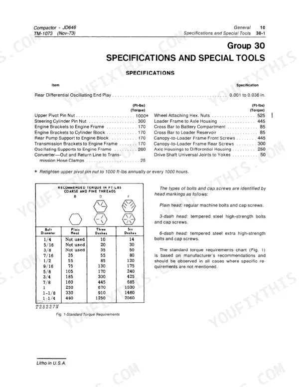
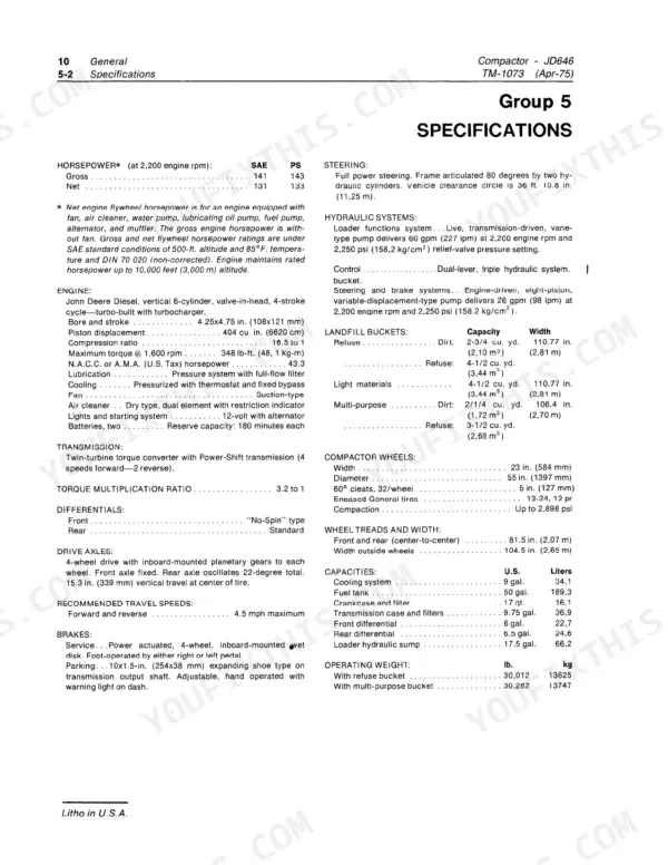
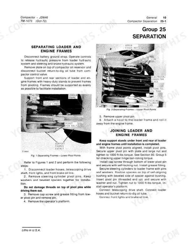
Part of the John Deere Repair Manuals.
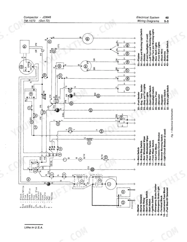
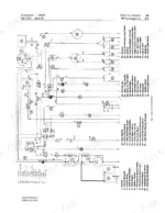
Looking for a John Deere JD646 technical manual PDF you can actually trust? This 309-page factory technical manual (OEM TM-1073) walks you through the whole JD646 Compactor: engine, fuel system, power train, steering, brakes, and loader hydraulics. Inside you get the full machine electrical schematic with numbered wiring charts, wire colors and routing, hydraulic circuit diagrams for the loader and the power steering with pressure testing and diagnosis, and exploded views that show exactly how every assembly comes apart. Troubleshooting charts run from the basic engine through the Robert Bosch injection nozzles to the transmission and differentials. Set engine oil pressure between 40 and 55 psi, torque the rocker arm clamp cap screws to 55 ft-lbs, and pull the camshaft gear cap screw to 85 ft-lbs. Forum threads won't rebuild your differential. Bookmarked and keyword-searchable; open it on any device and take it straight to the machine.
What's Inside This John Deere JD646 Manual
| System | Pages | Key Topics |
|---|---|---|
| General | 7-30 | Predelivery, Delivery, And After-Sale Services, Tune-Up and Adjustment, Lubrication, Compactor Separation, Specifications |
| Engine | 31-68 | Diagnosis, Basic Engine, Engine Lubrication, Speed Control Linkage, Engine Cooling |
| Fuel System | 69-90 | System Diagnosis; Tank, Filters and Transfer Pump; Air Intake System; Fuel Injection Pump; Robert Bosch Injection Nozzles |
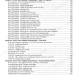
| Electrical System | 91-130 | Charging Circuit, Starting Circuit, Gauges and Switches, Wiring Diagrams |
| Power Train | 131-196 | Damper Assembly and Drive Shafts, Axle Assemblies, Differentials, Transmission Assembly, System Diagnosis |
| Power Steering and Brake Systems | 197-252 | General Information, Testing and Diagnosis; Hydraulic Pump; Filters, Oil Cooler and Accumulators; Steering System; Brake System |
| Hydraulic System | 253-286 | Reservoir and Filters, Return-to-Dig Valve, Cylinders, Control Valve, Hydraulic Pump |
| Miscellaneous Components | 287-309 | Frames, Buckets, Multi-Purpose Bucket, Demolition Wheels |
Every system also includes specifications and special tools.
Quick Reference Specifications
| Specification | Value | Page |
|---|---|---|
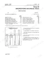
| Rocker arm clamp cap screws | 55 ft-lbs | p. 39 |
| Camshaft thrust plate cap screws | 20 ft-lbs | p. 41 |
| Engine oil pressure | 40 - 55 psi | p. 51 |
| Oil filter bypass valve spring free length | 3-3/8 in. | p. 66 |
| Air cleaner primary element replacement interval | 1 year | p. 76 |
| Intake manifold pressure | 12 to 15 psi | p. 78 |
| Battery voltage | 12 volts | p. 100 |
| Battery BCI group | 30H | p. 100 |
| Alternator through bolts torque | 50 to 60 in-lbs | p. 107 |
| Starting circuit relay 5/16 inch terminal nuts torque | 35 in-lbs | p. 127 |
| Rear output flange nut torque | 600 to 700 lb-ft (814 to 949 N-m) | p. 169 |
John Deere JD646 Common Problems This Manual Covers
Engine starts hard, starts and stops, or won't develop full power under load
Start with the fuel side: the engine carries one combination first and second stage filter element, plus a fuel line filter ahead of the transfer pump and a strainer in the tank that rinses clean in fresh fuel (page 72). Swap the air cleaner primary element at least once a year per page 76. With the engine under load at 2200 rpm, measure intake manifold pressure; it should read 12 to 15 psi (page 78). Bleed the injection lines after any filter change.
Manual Section: Fuel System Diagnosis p. 72Loader boom and bucket move slow, jerky, or boom won't stay raised
Check hydraulic oil level with the boom down and inspect the reservoir pressure cap; its pressure valve should hold 12 to 15 psi (page 262). Clean or replace the reservoir filters, and measure the filter relief valve spring against its 2.81 inch free length spec on page 285. Hunt for suction side air leaks that foam the oil.
Manual Section: Hydraulic System Diagnosis (Loader Functions) p. 262Machine jerks, slips, or lacks power moving through gears in either direction
Check transmission oil level and condition first; burnt smell or foam means the fluid is done. Hook up a gauge and verify main pressure runs 160 to 205 psi at operating temperature (page 147). Low pressure points to a plugged filter or worn charge pump. Adjust the shift linkage before you condemn the clutch packs.
Manual Section: Transmission Malfunction Diagnosis p. 147Engine overheats and loses power during heavy compaction work in warm weather
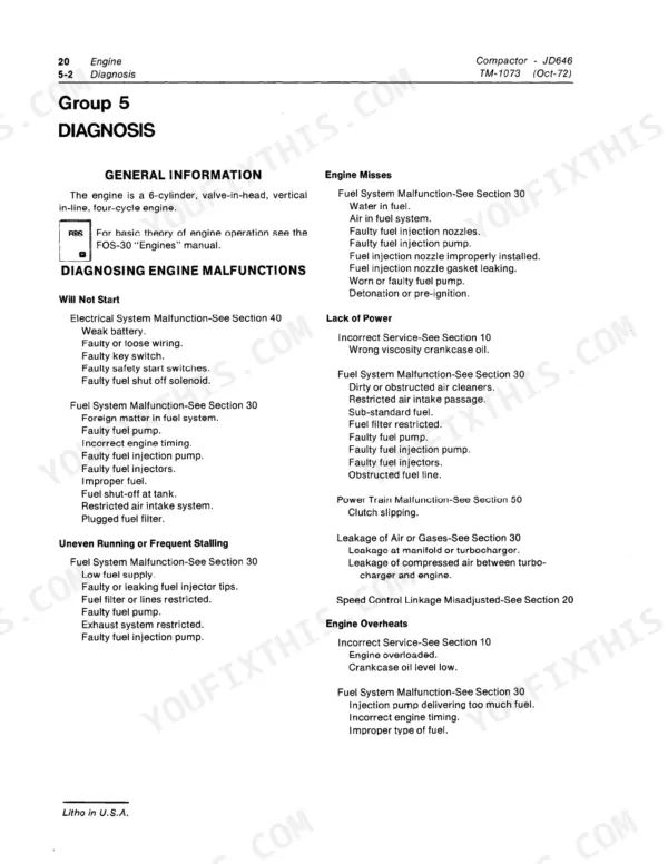
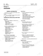
Blow chaff and debris out of the radiator core and screens daily in dusty conditions, then check coolant level, mix, and belt tension. Work through the overheating chart on page 32 for thermostat and water pump checks. Watch the oil gauge too; pressure should hold 40 to 55 psi at rated speed (page 51).
Manual Section: Engine Diagnosis p. 32Frequently Asked Questions
What are the replacement specifications for the engine oil filter?
The engine oil filter is a full-flow, screw-on replaceable element. Turn the element down by hand until tight, then fill the engine with the specified oil, start the engine and check for leaks around the element. For fuel-filter replacement intervals the technical manual refers you to the operator's manual (page 72). p. 66
What is the correct torque for the cylinder head cap screws?
The manual gives a three-step sequence on page 38: tighten the cap screws in the Fig. 5 sequence to 100 ft-lbs, repeat the sequence at 115 ft-lbs, then after break-in loosen the No. 1 cap screw 5 to 10 degrees and tighten it to 130 ft-lbs, following the same sequence for each screw. The specifications table on page 63 lists the first pass as 110 ft-lbs, so check both pages before you torque. p. 38
What is the specified valve tappet clearance for the engine?
The valve tappet clearance for the intake valves is 0.018 inch, and for the exhaust valves, it is 0.022 inch. p. 17
How do you fix a John Deere JD646 compactor that won't start, cranks slow or is dead in cold mornings?
Test the battery first: it needs a full 12 volts and 570 cold cranking amps at 0°F (page 125). Clean and tighten both cable ends and the ground strap. Check the starting circuit relay next, torquing the 5/16 inch terminal nuts to 35 in-lbs per page 127. If the starter still drags, load test and replace the battery. p. 125
Is this John Deere JD646 manual a PDF I download?
This is a 309-page searchable PDF ready for immediate download. Works on any device, so pull it up on your phone while you're under the hood. No shipping, no waiting.
Can I print this John Deere JD646 manual?
Yes. Print the pages you need for the job in your own shop, and bin them when they get greasy.
Does this John Deere JD646 manual show the hydraulic circuits?
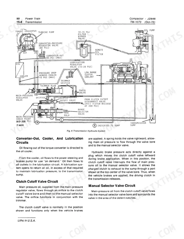
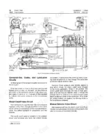
Yes. Page 144 prints the transmission hydraulic system circuit (Fig. 6) with the main-pressure check point at 160 to 205 psi, and page 254 the loader-functions hydraulic system circuit. Page 199 shows the power steering and brake hydraulic system, and pages 220 and 221 the right-hand and left-hand steering circuits with pressure, return and trapped oil color-coded. p. 144







Reviews
There are no reviews yet.