


One job runs through all 371 pages of this Kubota 07-CR-E5, 07-CR-TE5, 07-CR-TIE5, DM Diagnostic Manual PDF (OEM #9Y310-00072): find the fault in your common rail fuel system and clear it. Over 250 pages walk every DTC and its diagnostic procedure. Another 36 pages handle symptom-based diagnosis for hard starts, idle failure, black smoke, and poor acceleration. Ten pages of wiring diagrams cover the engine, injector, and ECU intermediate harnesses, with full ECU pin assignments mapped on both engine and machine sides. Check injector resistance between terminals at 0.35 to 0.55 ohms. Confirm the pump difference learning correction stays within ±200 mA at idle near 800 rpm. No more chasing phantom codes with a generic scan tool. Bookmarked by section, opens on laptop or tablet, ready to walk out to the machine.
What's Inside This Kubota 07-CR-E5, 07-CR-TE5, 07-CR-TIE5, DM Manual
| System | Pages | Key Topics |
|---|---|---|
| Information | 3-9 | Safety First |
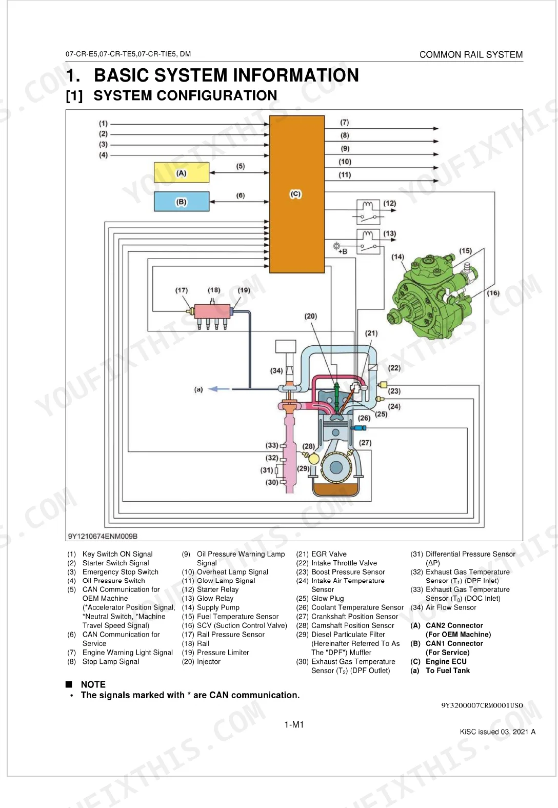
| Basic System Information | 10-10 | System Configuration |
| Intake and Exhaust System | 12-12 | - |
| Wiring Diagram | 13-21 | Engine Intermediate Harness, Injector Intermediate Harness, Engine Ecu Intermediate Harness, System Wiring Diagram |
| Available Data Monitor Signals | 22-27 | Available Data Monitor Signals (Monitor Items, Normal Value) |
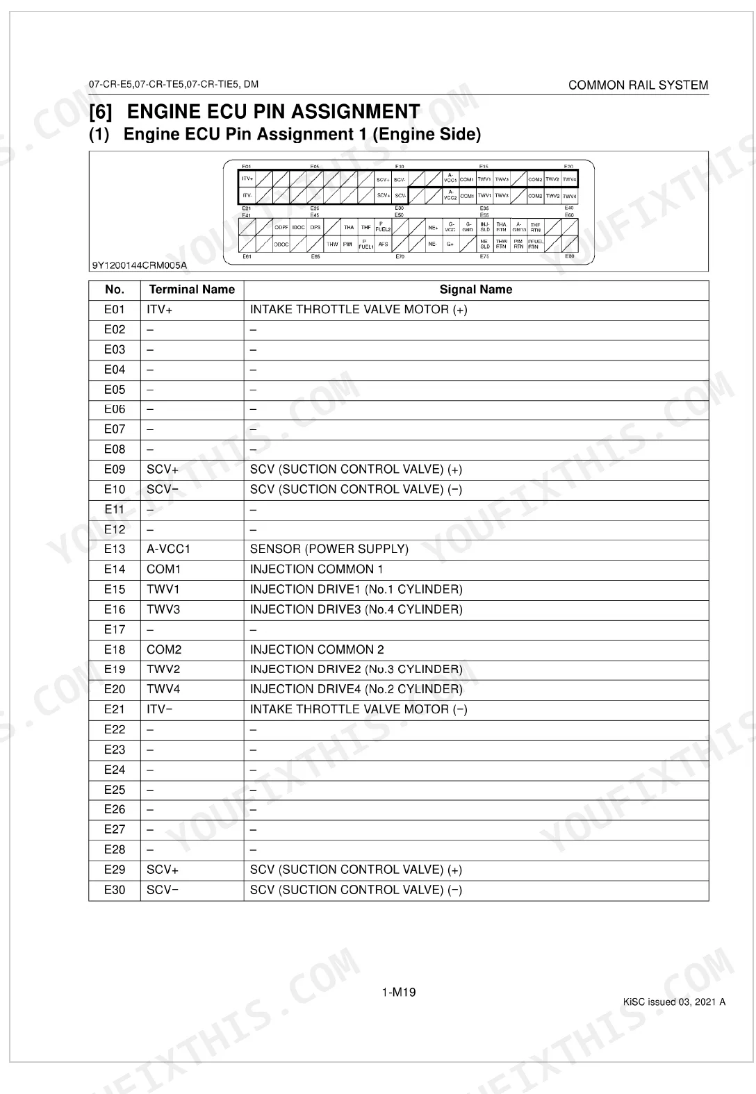
| Engine Ecu Pin Assignment | 28-38 | Engine Ecu Pin Assignment 1, Engine Ecu Pin Assignment 2 |
| General Diagnostics | 39-45 | General (Overall Diagnostic Procedure, Questioning, List Of Malfunction Symptom, Actions For Non-Reoccurring Malfunctions) |
| Diagnostic Tool Connection Procedure | 46-54 | Diagnostic Connector Positions, Checking The Communication Operation Of The Interface, Checking The Operation Of The Engine Ecu |
| Active Test and Utility | 55-63 | - |
| Diagnosis by Malfunction Symptom | 64-103 | Engine Warning Light Comes On, Takes a Long Time Before Engine Starts, Idle Failure, Engine Noise, High Fuel Consumption, Poor Acceleration, Abnormal Black Smoke Emitted, Abnormal White Smoke Emitted |
| Diagnostic Procedure by Dtc | 104-358 | Diagnostic Procedure By Dtc (Dtc List, Diagnostic Procedure By Dtc) |
| Inspection Procedure for Each System | 359-371 | Inspection Procedure For Each System (Air Intake System Inspection Procedure, Fuel System Inspection Procedure, Electric System Inspection Procedure) |
Quick Reference Specifications
| Specification | Value | Page |
|---|---|---|
| Fuel filter replacement interval | every 500 operation hours | p. 363 |
| Pump difference learning correction value | must be within ± 200 mA | p. 184 |
| Resistance between injector terminals | 0.35 to 0.55 Ω | p. 223 |
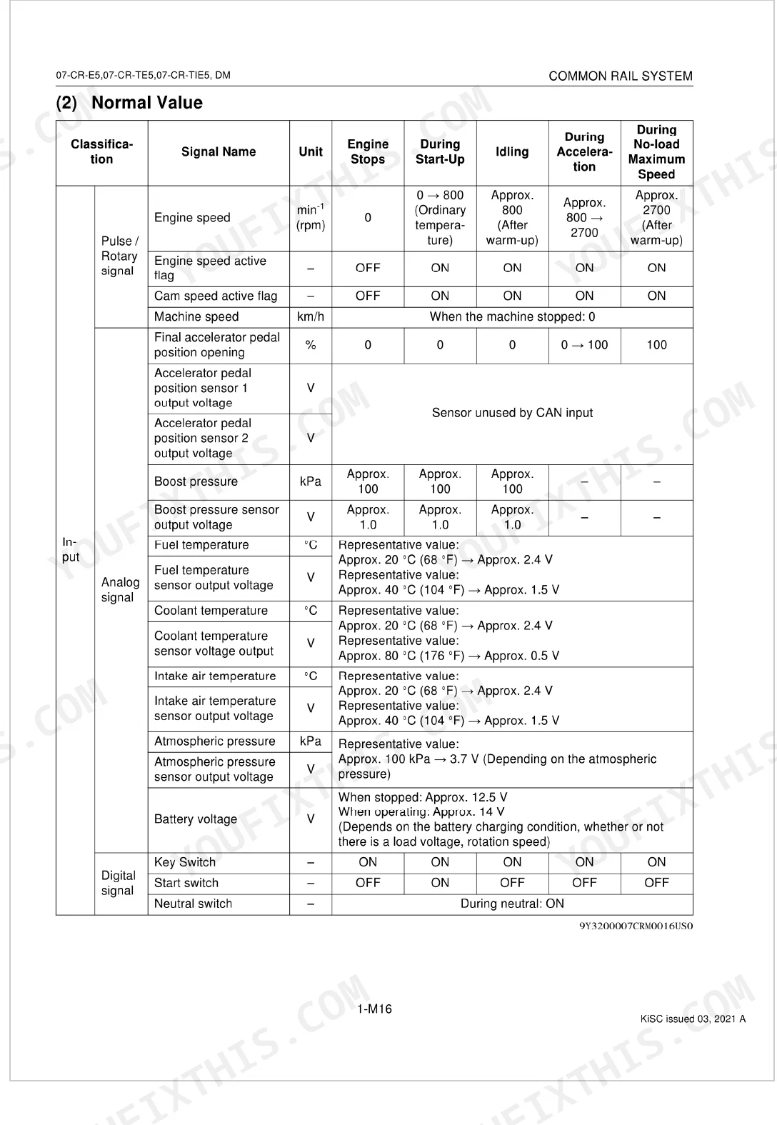
| Engine Speed (Idling) | Approx. 800 rpm | p. 25 |
| Engine Speed (No-load Maximum) | Approx. 2700 rpm | p. 25 |
| Target Rail Pressure (Idling) | Approx. 30 MPa | p. 26 |
| Target Rail Pressure (No-load Maximum) | 95.0 to 115 MPa | p. 26 |
| Actual Suction Control Valve (SCV) Current (Idling) | Approx. 1800 mA | p. 26 |
| Intake Air Temperature Sensor Resistance (at 20 °C / 68 °F) | Approx. 2.43 kΩ | p. 173 |
| Coolant Temperature Sensor Resistance (at 20 °C / 68 °F) | Approx. 2.5 kΩ | p. 181 |
| Fuel Temperature Sensor Resistance (at 20 °C / 68 °F) | Approx. 2.5 kΩ | p. 187 |
| Injector Resistance | 1.5 Ω or lower | p. 216 |
Kubota 07-CR-E5, 07-CR-TE5, 07-CR-TIE5, DM Common Problems This Manual Covers
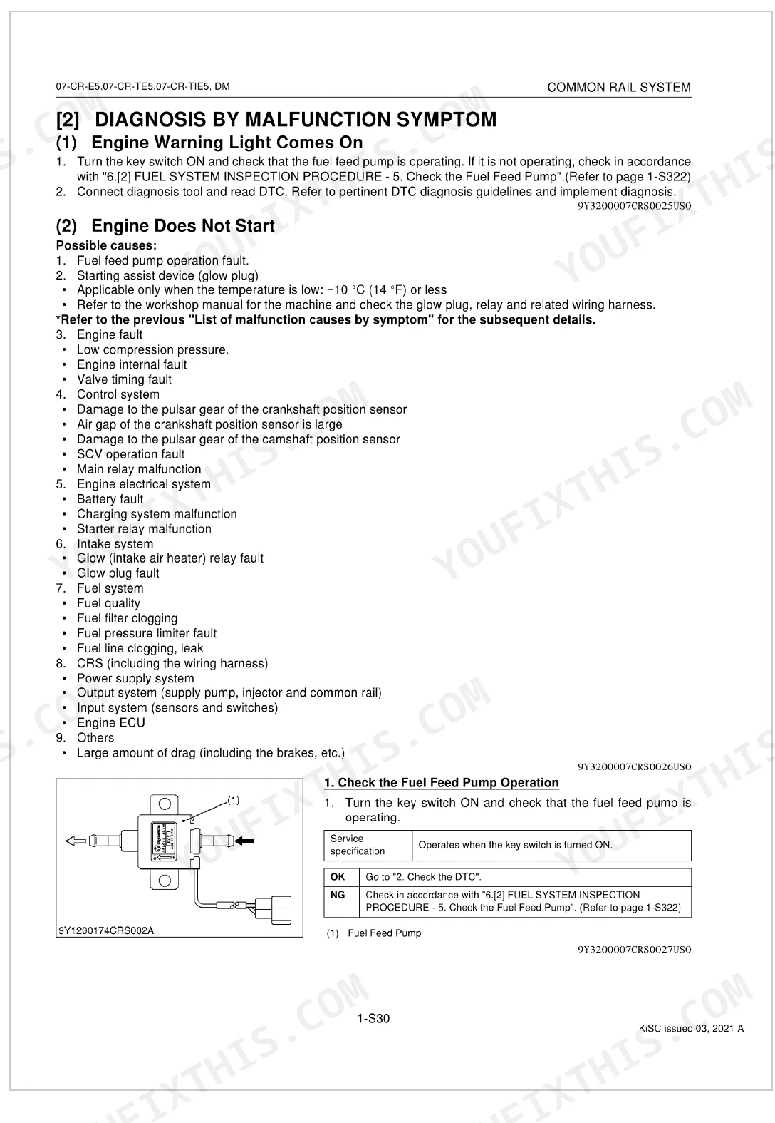
Engine cranks but will not start on the 07-CR-E5, warning light stays lit after a key cycle p. 68
Connect the diagnostic tool and pull stored DTCs following the procedure on page 46. Verify rail pressure hits approximately 30 MPa at idle (page 26). When pressure is low, measure SCV resistance at the connector. It should read approximately 2.1 Ω at 20 °C (page 225). Swap the SCV if it falls out of spec.
Manual Section: Engine Warning Light Comes On / Engine Does Not StartCranks for too long before the engine fires, no fault codes stored p. 72
Run the fuel system inspection on page 359. Check primary and secondary filters first; replacement interval is every 500 operation hours (page 363). Bleed air from the lines, then confirm lift pump delivery. Verify fuel cetane rating of 45 minimum and sulfur content under 15 ppm (page 360) before condemning hardware.
Manual Section: Takes a Long Time Before Engine StartsSputters and dies after 30 to 40 minutes of runtime, restarts fine once cool p. 360
Suspect fuel starvation from a heat-affected lift pump or a clogging filter. Inspect the fuel filter and pickup screen using the fuel system procedure on page 359. Watch actual SCV current on the data monitor: approximately 1800 mA at idle is normal, and a drifting value points to pump wear. Confirm pump difference learning correction stays within ±200 mA (page 184).
Manual Section: Fuel System Inspection ProcedurePoor acceleration and reduced power under load, no abnormal smoke at the stack p. 86
Monitor target rail pressure climbing to 95.0 to 115 MPa at no-load maximum (page 26). If actual pressure trails the target, test injector resistance at each connector. Readings must be 1.5 Ω or lower, with terminal-to-terminal resistance between 0.35 and 0.55 Ω (page 223). Replace any injector outside spec and inspect the high-pressure lines.
Manual Section: Poor Acceleration (Insufficient Output)White smoke at idle and light load with rough running p. 91
Drain a fuel sample and look for water contamination before any electrical testing. Work through the abnormal smoke procedure starting on page 91. Measure fuel temperature sensor resistance, approximately 2.5 kΩ at 20 °C (page 187), and coolant temperature sensor resistance, approximately 2.5 kΩ at 20 °C (page 181). A cold-reading coolant sensor skews injection timing and produces white smoke.
Manual Section: Abnormal Smoke (Black or White)Black smoke under acceleration with climbing fuel consumption p. 91
Check the air intake for restriction and post-filter leaks using the procedure on page 359. Then verify intake air temperature sensor resistance reads approximately 2.43 kΩ at 20 °C (page 173); a skewed IAT signal causes over-fueling. Confirm no-load maximum engine speed reaches approximately 2700 rpm (page 25) and test injectors for leakage at 1.5 Ω or lower terminal resistance (page 216).
Manual Section: Abnormal Black Smoke EmittedFrequently Asked Questions
What are common error codes on Kubota V2607-CR-E5 engines?
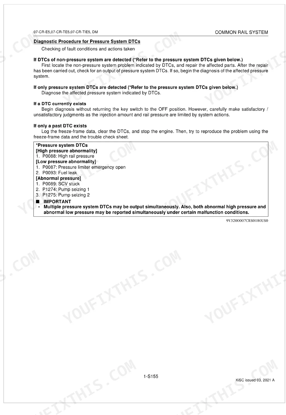
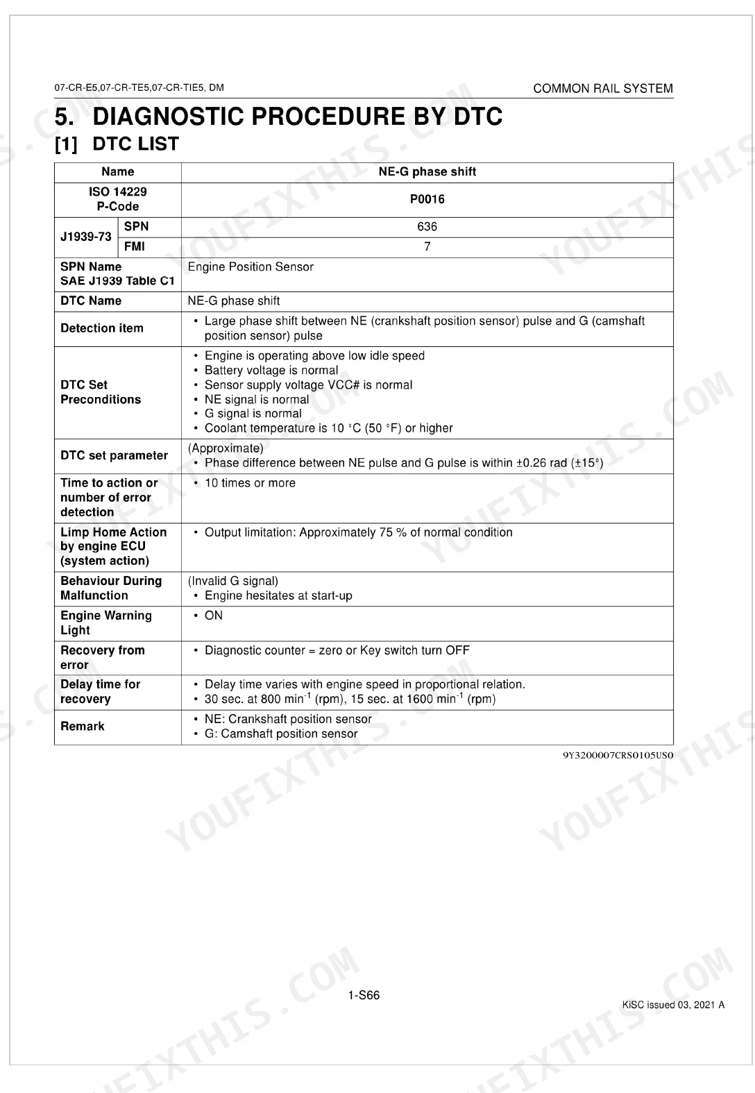
The manual lists many DTCs tied to engine sensors and fuel pressure. Frequent ones include P0016 for a phase shift between crankshaft and camshaft sensors, P0088 for high rail pressure, and P0089 for a stuck suction control valve (SCV). The full DTC list with diagnostic procedures begins on page 1-S132.
How to reset DPF regeneration on Kubota 07 Series CR-E5?
Certain DPF-related DTCs, such as P3008 for excessive PM accumulation, can be cleared with a service tool. Turn the key switch OFF, then use the service tool to perform the reset.
How to check fuel pressure on Kubota common rail engines?
Fuel pressure is read through the data monitor on a diagnostic tool. Connect the tool and watch the 'Target rail pressure' and 'Actual rail pressure' values. Idle should sit at 40 to 50 MPa (5800 to 7200 psi). At no-load maximum, expect 95.0 to 115 MPa (13800 to 16600 psi).
How to perform forced DPF regeneration Kubota 07-CR-E5
Forced DPF regeneration runs through the active test function on a diagnostic tool. When a DTC like P3007 (Excessive PM4) triggers, connect the tool and start the 'DPF Manual Regeneration' active test to burn off accumulated particulate matter.
What format is this Kubota 07-CR-E5, 07-CR-TE5 manual in?
A 371-page Diagnostic Manual in searchable PDF, delivered the moment checkout completes. Open it on a computer, tablet, or phone with no shipping wait.
Am I able to print pages from this Kubota 07-CR-E5, 07-CR-TE5 manual?
No restrictions. Print individual pages, full chapters, or the whole manual. The PDF is fully unlocked.
Does this Kubota 07-CR-E5, 07-CR-TE5 Diagnostic Manual have electrical diagrams?
Yes. The 07-CR-E5, 07-CR-TE5 Diagnostic Manual includes full electrical wiring diagrams, wire routing, and connector pinouts.
Document Quality
This is a native digital PDF, allowing you to search and copy the full text. The text is consistently sharp, and system diagrams are high-quality vector graphics that remain clear when zoomed. Photographs of components and software screenshots are raster images; while perfectly usable, they can appear slightly soft or grainy. The document is clean with no scan artifacts, and it includes several section title pages.

Reviews
There are no reviews yet.