
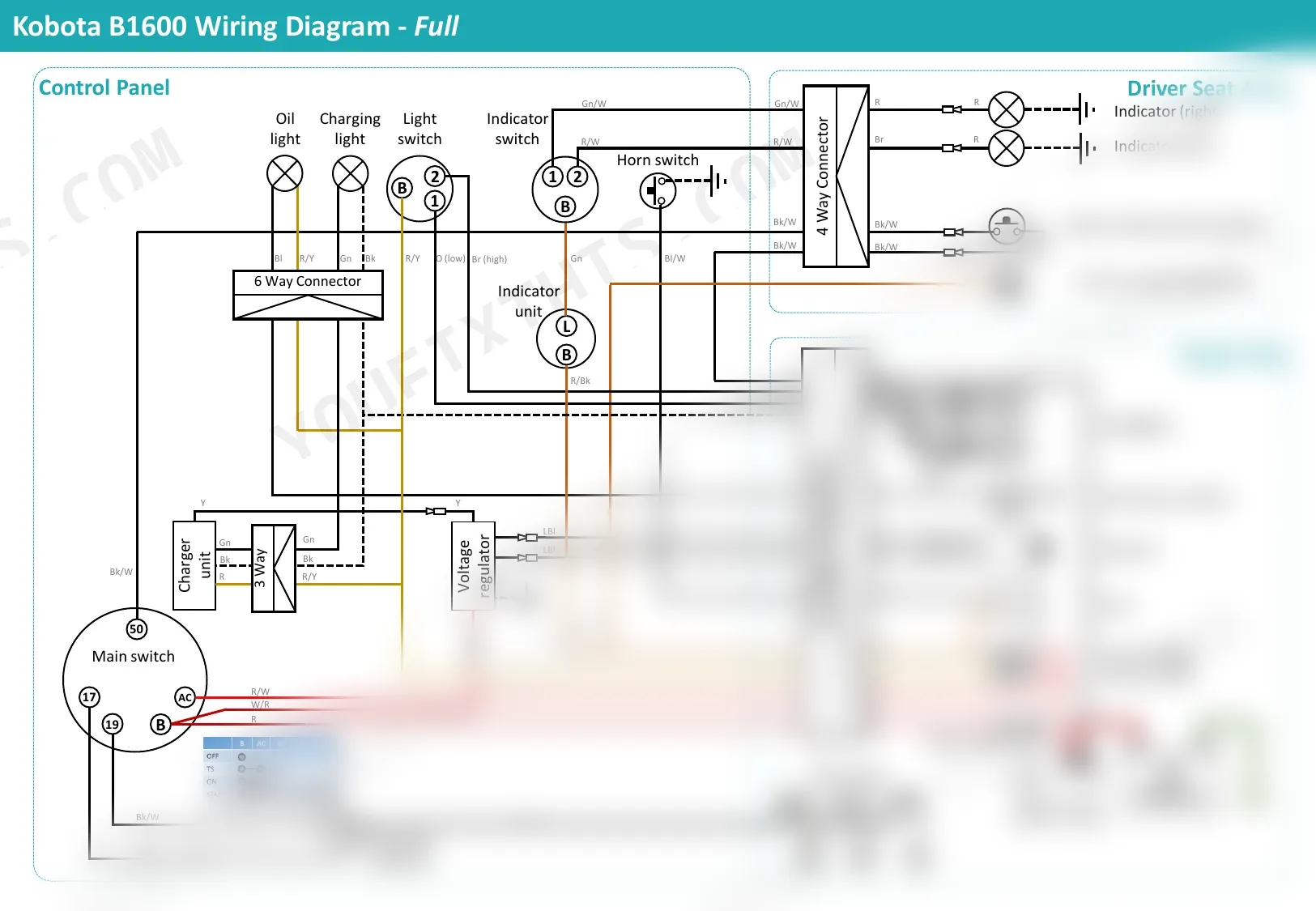
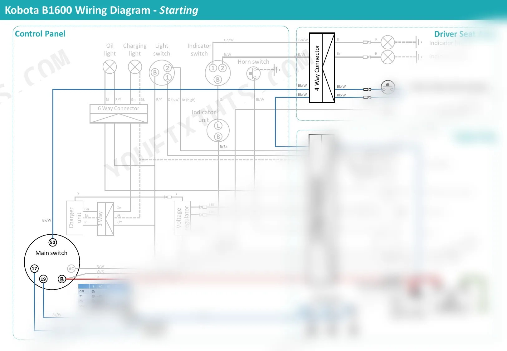
Four pages, one job: the B1600's electrical system mapped circuit by circuit. The factory wiring diagram is split across four focused sheets covering control panel, driver seat area, engine bay, main switch, 12V battery, and fuse layout. You also get the power supply and charging circuit (dynamo, voltage regulator, charger unit on the 3 Way connector, charging light), the lighting circuit with indicator and horn switches, and the starting circuit tracing safety switch, starter motor, and glow plug indicator. Confirm 12V at the battery, check both T1 and T2 fuses at 25A, verify the 0.5mm fuse link before chasing anything deeper. No more poking wires with a multimeter and a prayer. Bookmarked PDF opens on any device, so the tablet comes with you to the tractor.
What's Inside This Kubota B1600 Manual
| System | Pages | Key Topics |
|---|---|---|
| Full Wiring Diagram | 1 | Control Panel, Driver Seat Area, Engine Bay, Main Switch, 12V Battery, Fuses And Fuse Link |
| Power Supply & Charging | 2 | 12V Battery, Main Switch, Dynamo, Voltage Regulator, Charger Unit, Charging Light |
| Lights | 3 | Light Switch, Indicator Switch, Headlights, Indicator, Horn Switch |
| Starting | 4 | Main Switch, Starter Safety Switch, Starter Motor, Glow Plugs, Glow Plug Indicator, 12V Battery |
Quick Reference Specifications
| Specification | Value | Page |
|---|---|---|
| Battery Voltage | 12V | p. 1 |
| Fuse T1 Rating | 25A | p. 1 |
| Fuse T2 Rating | 25A | p. 1 |
| Fuse Link Size | 0.5mm | p. 1 |
| Auxiliary Socket Voltage | 12V | p. 1 |
| Control Panel Connector Size | 6 Way | p. 1 |
| Driver Seat Area Connector Size | 4 Way | p. 1 |
| Main Harness Connector Size | 12 Way | p. 1 |
| Charger Unit Connector Size | 3 Way | p. 1 |
Kubota B1600 Common Problems This Manual Covers
B1600 cranks but refuses to start, worst after a cold night sitting outside p. 4
Test the battery first. It must hold 12V at rest and stay above 10.5V during cranking. Inspect the main switch and starter safety switch per the starting circuit on page 4. Verify glow plugs draw current when preheat is active. Replace any plug reading open on a continuity check.
Manual Section: StartingCharging light stays lit while running, battery goes flat after a few hours of work p. 2
Measure battery voltage with the engine at fast idle. A healthy charging circuit reads 13.8 to 14.4V at the 12V battery posts. If output stays at 12V or drops, inspect the dynamo, voltage regulator, and charger unit on the 3 Way connector. Clean corroded terminals and check the fuse link before condemning the regulator.
Manual Section: Power Supply & ChargingStarter clicks but the engine won't turn over, or cranks weakly then stops p. 4
Pull the starter safety switch lead and jumper it to confirm the safety interlock isn't blocking the circuit. Check the solenoid trigger wire from the main switch. Clean battery cable ends and torque the post clamps snug. Voltage at the solenoid must stay above 10V under load. Replace the starter if internal resistance is high.
Manual Section: StartingHeadlights flicker, indicators dead on one side, horn intermittent p. 3
Walk the light switch and indicator switch connections first. Loose pins in the 6 Way control panel connector cause flicker. Inspect ground straps from the headlight buckets to the frame. Clean both ends with a wire brush and dielectric grease. If only one indicator fails, swap bulbs side to side to isolate bulb from wiring per the lights circuit on page 3.
Manual Section: LightsAuxiliary socket dead, accessories cut out, random electrical gremlins under the dash p. 1
Pull fuses T1 and T2 and confirm both are 25A. A blackened fuse holder means heat damage; replace the holder, not just the fuse. Check the 0.5mm fuse link near the battery for a hairline break. Trace the 12 Way main harness connector for backed-out pins. Reseat each pin until it clicks and tug-test before reassembly.
Manual Section: Full Wiring DiagramGlow plug indicator never lights, engine fires hard or not at all below 5°C p. 4
With the main switch in preheat, the glow plug indicator should illuminate within 5 seconds. If it stays dark, check the indicator bulb, then measure voltage at the glow plug bus. Each plug should draw roughly 10A at 12V. Pull plugs one at a time and test for continuity to the tip. Swap any open plug as a set for even preheat.
Manual Section: StartingFrequently Asked Questions
What are the replacement specifications for battery?
The wiring diagram specifies a 12V battery. Positive connects to the starter motor through a fuse link; negative grounds to the chassis. No other specs (group size, cold cranking amps) are provided.
How quickly can I access this Kubota B1600 manual after buying?
Immediate download of the full 4-page searchable Technical Manual. Open it on any device, laptop at the desk or phone out by the tractor.
Can I print this Kubota B1600 manual?
No restrictions. The PDF is DRM-free, so print whatever sections you want for the shop. Standard letter or A4 paper works.
Can I find wiring schematics in this Kubota B1600 manual?
This is a short technical manual. It includes a basic wiring diagram (pages 1–4) showing the 12V electrical circuit — battery, starter motor, fuse link, and chassis ground. It is a simplified diagram, not full workshop electrical schematics with connector pinouts and wire color codes — for complete schematics, refer to the Kubota B1600 workshop/service manual.
Document Quality
This is a native digital PDF containing a set of four color-coded wiring diagrams for the Kubota B1600. The diagrams are high-quality vector graphics, ensuring they remain sharp and clear at any zoom level, and all text and labels are fully searchable. The document provides a full wiring diagram, along with three additional pages that highlight the power supply, lighting, and starting circuits individually. The pages are clean and free of any marks or scan artifacts.


Reviews
There are no reviews yet.