


Every assembly on the B21 compact tractor is broken down across 365 bookmarked pages, each exploded diagram tying numbered balloons directly to factory part numbers. You'll find 182 pages of parts lists and cross-references spanning engine, drivetrain, hydraulic, and cab components. Need a +0.5mm oversize piston or a -0.2mm undersize crankpin bearing set? Those callouts are spelled out, along with 0.20mm injection pump shims and fuse ratings from 5A up to 50A. The catalog is organized by system: open the engine, drivetrain, hydraulics, or cab group and keyword-search any part number. Order the wrong number and the job stalls. Order the right one and you're back in the seat.
What's Inside This Kubota B21 Parts Manual
| System | Pages |
|---|---|
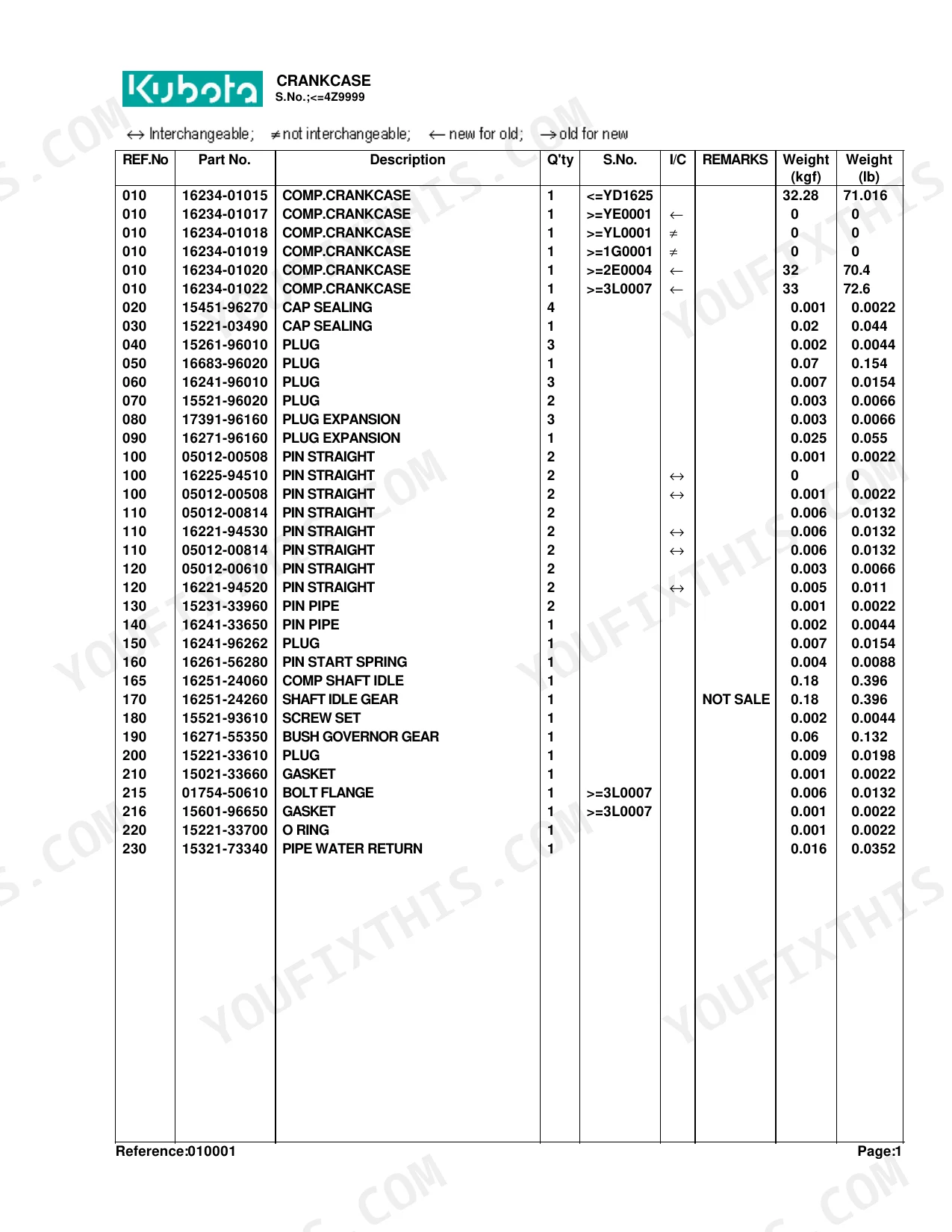
| Crankcase | 7-10 |
| Oil Pan | 11-12 |
| Cylinder Head | 13-15 |
| Gear Case | 16-18 |
| Head Cover | 19-22 |
| Oil Filter | 23-24 |
| Main Bearing Case | 25-26 |
| Camshaft and Idle Gear Shaft | 27-28 |
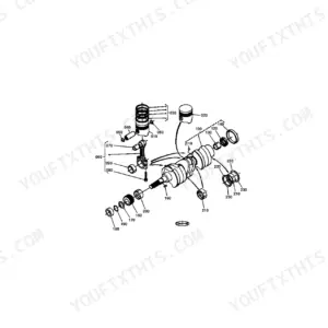
| Piston and Crankshaft | 29-31 |
| Flywheel | 32-33 |
| Fuel Camshaft and Governor Shaft | 34-35 |
| Idle Apparatus | 36-39 |
| Injection Pump | 40-41 |
| Governor | 42-48 |
| Speed Control Plate | 49-50 |
| Nozzle Holder and Glow Plug | 51-55 |
| Nozzle Holder [Component Parts] | 56-59 |
| Fuel Pump(Mechanical) | 60-61 |
| Water Flange and Thermostat | 62-63 |
| Water Pump | 64-65 |
| Valve and Rocker Arm | 66-68 |
| Inlet Manifold | 69-72 |
| Exhaust Manifold | 73-74 |
| Air Cleaner | 75-76 |
| Muffler | 77-79 |
| Upper Gasket Kit | 80-84 |
| Lower Gasket Kit | 85-88 |
| Accelerator Lever | 89-91 |
| Fuel Tank | 92-94 |
| Fuel Pipe | 95-99 |
| Fuel Filter [Component Parts] | 100-101 |
| Fan | 102-103 |
| Water Pipe | 104-105 |
| Radiator [Except [Au]] | 106-107 |
| Radiator [Au] | 108-109 |
| Stop Solenoid | 110-112 |
| Alternator | 113-114 |
| Alternator [Component Parts] | 115-116 |
| Starter | 117-118 |
| Starter [Component Parts] | 119-120 |
| Battery | 121-122 |
| Switch | 123-125 |
| Panel Board | 126-127 |
| Panel Board [Component Parts] | 128-129 |
| Head Light | 130-131 |
| Hazard Light | 132-133 |
| Tail Light | 134-138 |
| Winker Lamp | 139-140 |
| Electrical Wiring | 141-142 |
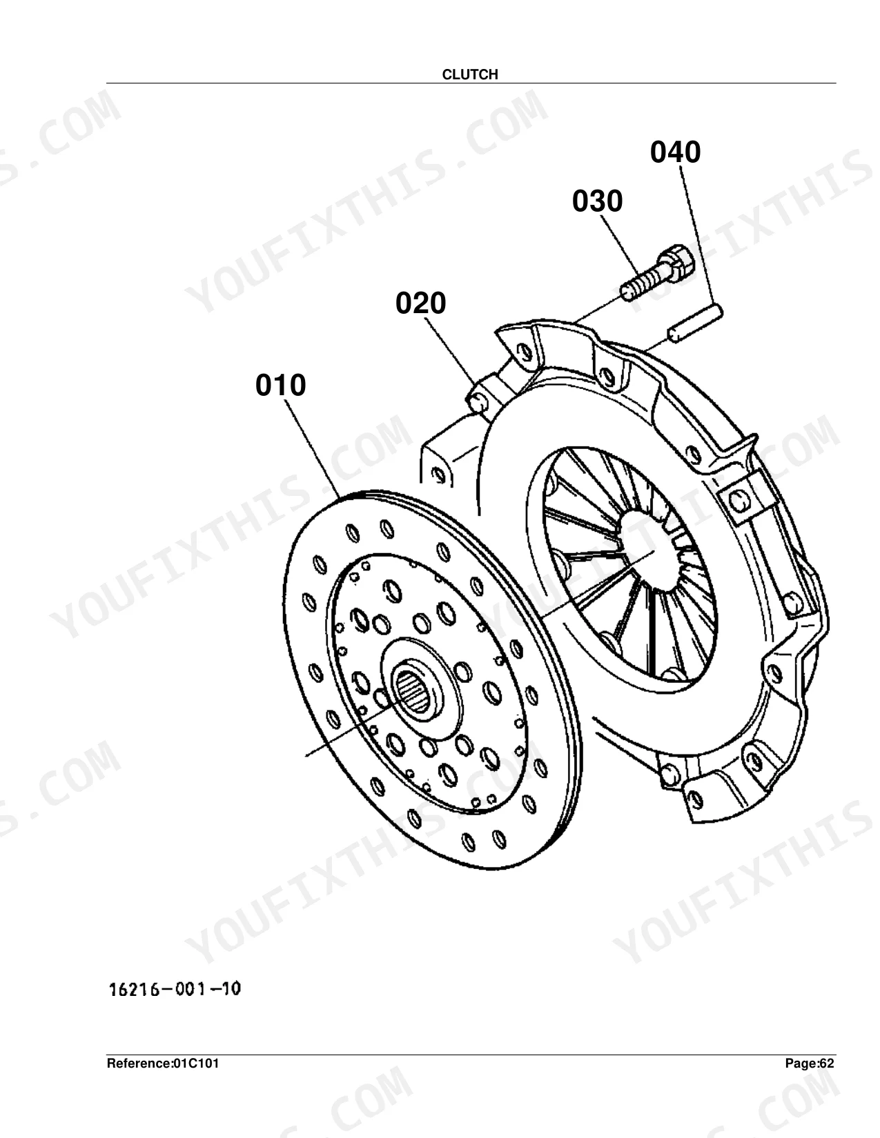
| Clutch | 143-144 |
| Clutch Rod | 145-146 |
| Clutch Pedal | 147-148 |
| Clutch Housing | 149-151 |
| Center Frame | 152-153 |
| Transmission Case | 154-155 |
| Differential Gear Case | 156-157 |
| Rear Axle Case | 158-160 |
| Clutch Shaft | 161-162 |
| Propeller Shaft | 163-164 |
| HST | 165-166 |
| HST [Component Parts] | 167-172 |
| Front Shaft | 173-174 |
| 2Nd Shaft/3Rd Shaft/4Th Shaft | 175-176 |
| PTO Shaft | 177-178 |
| Rear Differential | 179-180 |
| Front Wheel Propeller Shaft | 181-182 |
| Range Gear Shift Fork | 183-185 |
| Rear Axle | 186-187 |
| Brake | 188-189 |
| Parking Brake Lever | 190-191 |
| Neutral Holder Link | 192-194 |
| Speed Control Pedal | 195-197 |
| Range Gear Shift Lever | 198-200 |
| Range Gear Shift Rod | 201-203 |
| Front Wheel Drive Lever | 204-205 |
| PTO Gear Shift Lever | 206-208 |
| Hydraulic Control Lever | 209-210 |
| Hydraulic Change Rod | 211-212 |
| Brake Pedal | 213-215 |
| Differential Lock Pedal | 216-217 |
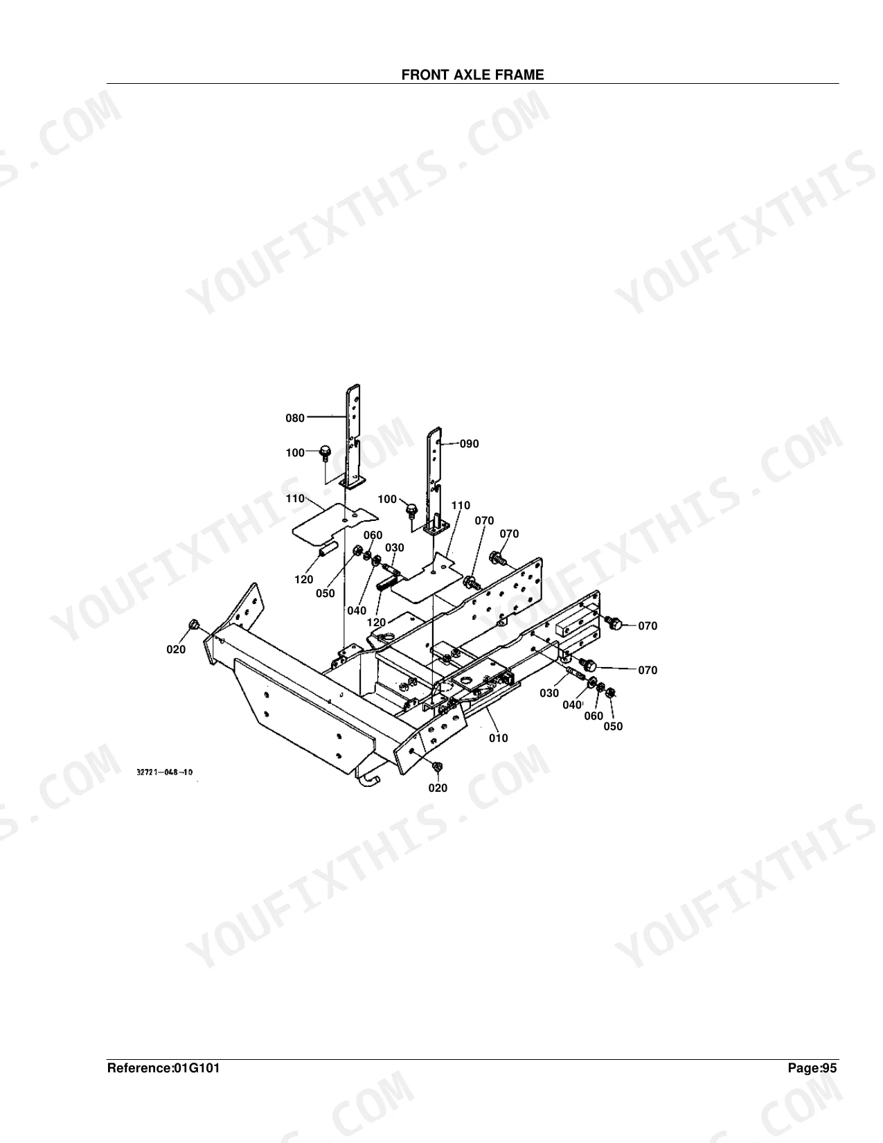
| Front Axle Frame | 218-219 |
| Front Axle Case | 220-222 |
| Front Differential | 223-225 |
| Bevel Gear Case | 226-227 |
| Front Axle | 228-230 |
| Front Drive Shaft | 231-233 |
| Drag Link | 234-235 |
| Tie Rod | 236-237 |
| Steering Handle | 238-239 |
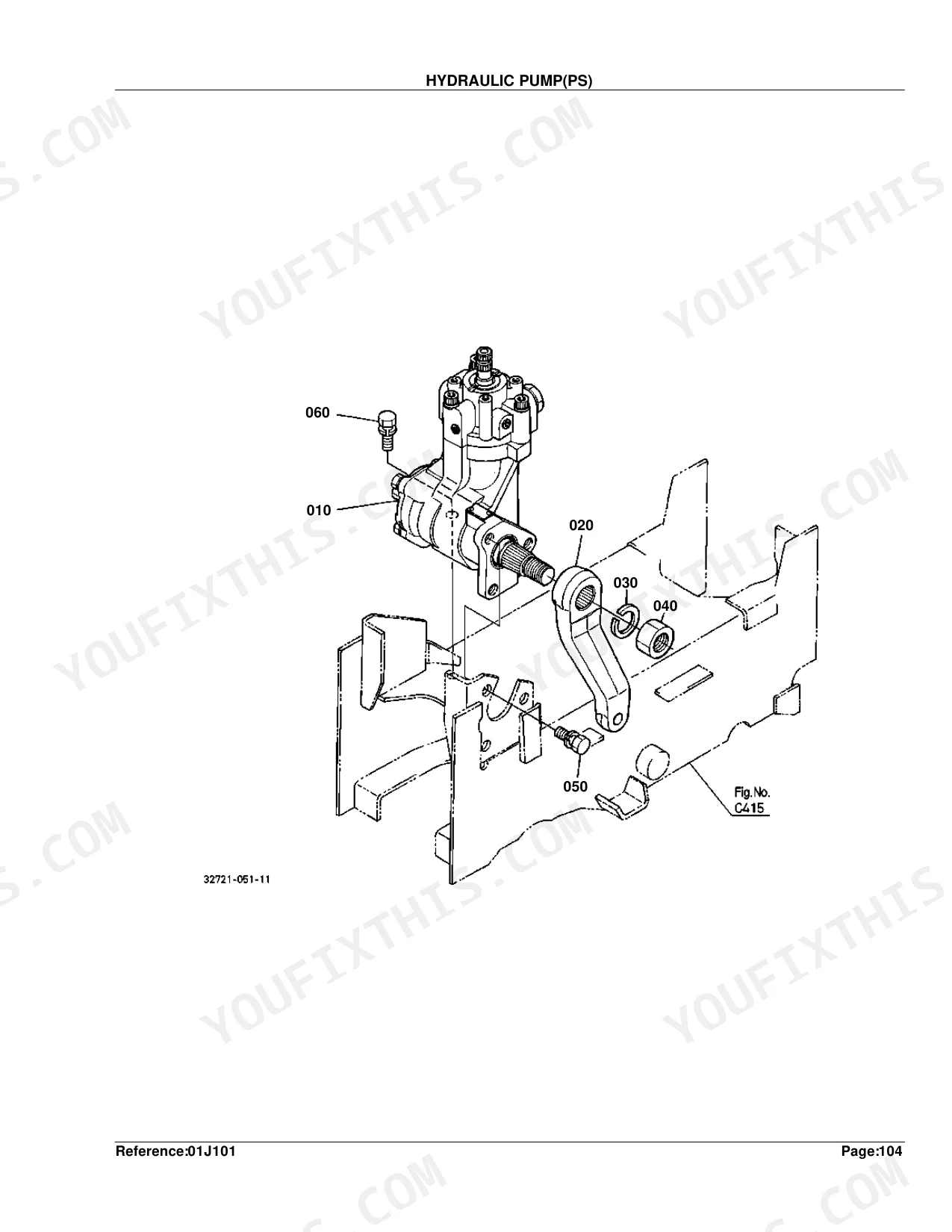
| Hydraulic Pump(Ps) | 240-241 |
| Hydraulic Pump(Ps) [Component Parts] | 242-247 |
| Hydraulic Pump | 248-249 |
| Hydraulic Pump [Component Parts] | 250-252 |
| Oil Tank | 253-254 |
| Hydraulic Oil Line(Suction) | 255-256 |
| Flow Divider Valve [Component Parts] | 257-258 |
| Hydraulic Oil Line(Delivery) | 259-261 |
| Hydraulic Oil Line(Steering) | 262-263 |
| Hydraulic Oil Line(Backhoe) | 264-266 |
| Hydraulic Oil Line(Hst) | 267-269 |
| Hydraulic Oil Line(Oil Cooler) | 270-272 |
| Hydraulic Oil Line(F/M) | 273-275 |
| Hydraulic Cylinder | 276-277 |
| Control Valve | 278-279 |
| Control Valve [Component Parts] | 280-281 |
| Hydraulic Outlet | 282-283 |
| Hydraulic Outlet [Component Parts] | 284-285 |
| 3-Point Linkage 2(Lift Rod) | 286-287 |
| Hitch/Lower Link | 288-289 |
| 3-Point Linkage 1(Top Link) | 290-291 |
| PTO Protector [Except [Au]] | 292-293 |
| PTO Protector [Au] | 294-295 |
| Bonnet [Except [Au]] | 296-298 |
| Bonnet [Au] | 299-301 |
| Panel Cover/Shutter Plate [Except [Au]] | 302-304 |
| Panel Cover/Shutter Plate [Au] | 305-307 |
| Fender Lh [Except [Au]] | 308-309 |
| Fender Lh [Au] | 310-311 |
| Fender Rh [Except [Au]] | 312-313 |
| Fender Rh [Au] | 314-315 |
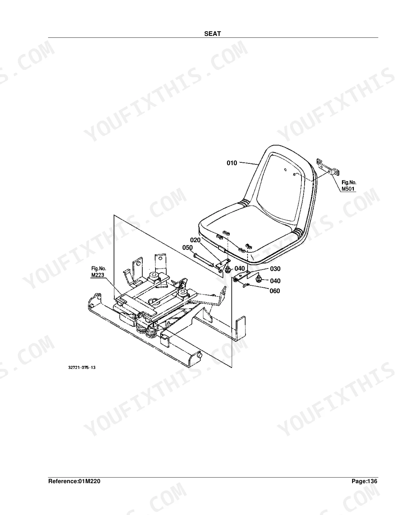
| Seat | 316-317 |
| Seat Turn Table | 318-319 |
| Base Seat Turn Table | 320-322 |
| Seat Adjuster | 323-324 |
| Step | 325-327 |
| Main Flame | 328-329 |
| ROPS/FOPS | 330-334 |
| Smv Emblem(Bracket) | 335-336 |
| Front Wheel(23*8.50-14R4) | 337-338 |
| Front Wheel(24*8.50-14) | 339-340 |
| Rear Wheel(12.4-16R4) | 341-342 |
| Rear Wheel(12.4-16) | 343-344 |
| Rear Wheel(13.6-16) | 345-346 |
| Label [A] [Ca] [English] | 347-349 |
| Label [A] [Ca] [French] | 350-352 |
| Label [Au] | 353-355 |
| Accessories and Service Parts | 356-357 |
| Working Light Kit [Option] | 358-361 |
| Wire Harness Kit [Option] [Au] | 362-363 |
| Drawber Kit [Option] | 364-365 |
Quick Reference Specifications
| Specification | Value | Page |
|---|---|---|
| FUSE | 50A | p. 142 |
| FUSE AUTO | 5A | p. 142 |
| SHIM INJECTION PUMP Thickness | 0.20mm | p. 41 |
| PISTON Oversize | +0.5mm | p. 30 |
| METAL CRANKPIN Undersize | -0.2mm SET | p. 30 |
| METAL CRANKSHAFT Undersize | -0.4mm | p. 30 |
| ASSY BATTERY | 12V36AH | p. 122 |
| FUSE Rating | 50A | p. 142 |
| FUSE AUTO Rating | 5A | p. 142 |
| BULB LIGHT Power | 27W | p. 133 |
| GEAR CLUTCH SHAFT Tooth Count | 23T | p. 162 |
| GEAR 4WD Tooth Count | 19T | p. 182 |
Kubota B21 Common Problems This Manual Covers
Kubota B21 fuel shutoff solenoid part number lookup, engine cranks over but will not start p. 110
Open the Stop Solenoid exploded view on page 110 and match the solenoid assembly to your serial number range in the parts index. Also confirm the 50A main fuse part number on the electrical parts list (page 142), since a blown fuse mimics a dead solenoid exactly.
Manual Section: Stop SolenoidNeed fuse and relay part numbers, gauges and electrical accessories cut out at random p. 142
Pull the electrical wiring parts list starting on page 141. The fuse breakdown on page 142 lists each rating separately, 5A, 10A, 15A, 20A, and the 50A main, so order by exact amperage. Cross-reference relay part numbers against your serial number range before buying, since early and late units differ.
Manual Section: Electrical WiringCan't find the battery and key switch part numbers, starter clicks weakly or does nothing p. 121
Start with the Battery section on page 121. The assembly is specified as 12V36AH on page 122, so match that rating exactly. For the key switch, pull up the Switch exploded view on page 123 and verify the part number against your serial number range before ordering.
Manual Section: BatteryLooking up headlight and tail light bulb part numbers, lights flicker or stay dark p. 130
Locate the Head Light parts diagram on page 130 and the Hazard Light list on page 132. The bulb is rated at 27W (page 133), so match wattage exactly when ordering. For rear lamps, reference the Tail Light exploded view on page 134 to confirm the correct bulb and lens part numbers.
Manual Section: Head LightNeed the hydraulic pump exploded view, 3-point hitch raises empty but struggles under implements p. 248
Begin with the hydraulic parts diagram on page 240, then move to the Hydraulic Pump exploded view on page 248 and its component parts list on page 250. Match the pump assembly to your serial number range. For the lift linkage, cross-reference the lift rod breakdown on page 286.
Manual Section: Hydraulic PumpFrequently Asked Questions
What are the replacement specifications for Hydraulic/HST filter?
The hydraulic oil line (HST) cartridge oil filter is part number 66021-36060. Quantity listed in the catalog is one.
What are the replacement specifications for Fuel filter?
The complete fuel filter assembly is 15751-43010. Its replacement element is listed separately as 1T021-43560.
What do I get after purchasing this Kubota B21 manual?
You'll receive a 365-page searchable PDF, available for immediate download. It works on any device, so you can pull it up on your phone right at the machine. No shipping, no waiting.
Am I able to print pages from this Kubota B21 manual?
No restrictions. Print individual pages, full chapters, or the entire manual. The PDF is completely unlocked.
Does this Kubota B21 manual include hydraulic schematics?
Yes, this parts catalog includes detailed exploded diagrams for all hydraulic components: pump, cylinder, and valves. It does not contain hydraulic circuit schematics.
Document Quality
This is a hybrid document where the parts lists and index pages are native digital, allowing you to search and copy all text, while the corresponding diagrams are scanned. The text on the parts lists is crisp and clear. The diagrams are scanned raster images that are legible at standard magnification but will appear pixelated when zoomed in. The scanned pages are generally clean, with only some minor specks and occasional slight page skew.


Reviews
There are no reviews yet.