


This Kubota B2301 and B2601 Shop Manual (OEM #9Y111-11560) is the factory book for both compact tractors, covering everything from hydrostatic transmission rebuilds to front axle teardowns across 341 pages. Hydraulic schematics map the HST pump and motor circuit, the front loader control valve, and the steering circuit, while the wiring diagrams trace the OPC safety system, charging, and lighting. Roughly 150 pages walk through disassembly and assembly, another 50 cover exploded views of every major system, and 20 troubleshooting charts span engine, transmission, brake, and electrical faults. The factory schedule sets rear wheel mounting nuts at 145 to 150 N·m and a hydraulic oil filter change every 400 hours, so you stop guessing intervals off a dirty sticker. Everything is bookmarked by system and keyword-searchable, ready on a tablet out in the shop.
What's Inside This Kubota B2301, B2601 Manual
| System | Pages | Key Topics |
|---|---|---|
| I Information | 3-13 | Safety First, Safety Decals, Specifications, Traveling Speeds, Dimensions |
| G General | 14-68 | Tractor Identification, Handling Precautions For Electrical Parts And Wiring (Battery, Fuse, Connector, Handling Of Circuit Tester, Color Of Wiring), Lubricants, Fuel And Coolant |
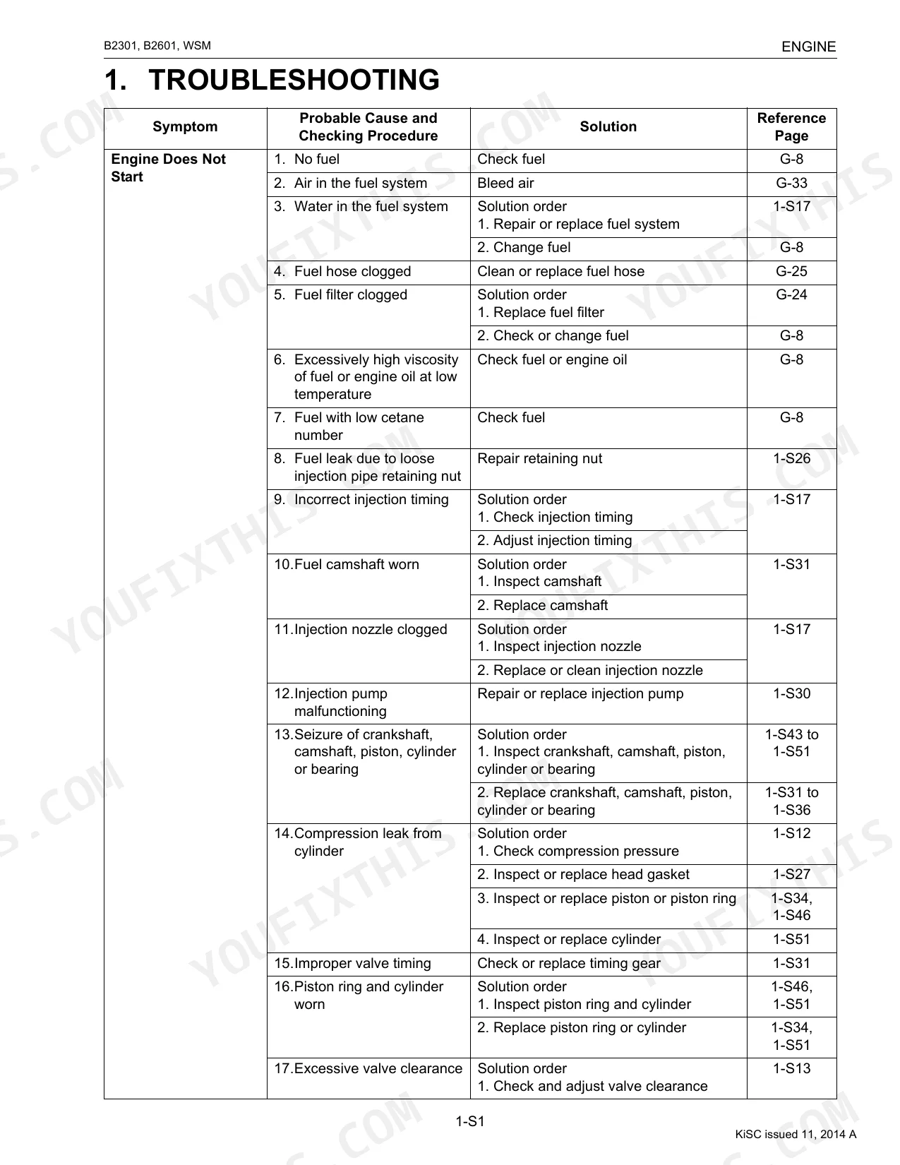
| 1 Engine | 69-126 | Engine Body (Closed Breather, Governor), Checking, Disassembling And Servicing (Checking And Adjusting, Preparation, Disassembling And Assembling), Servicing Specifications |
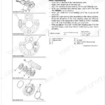
| 2 Transmission | 127-200 | Front Case, Hydrostatic Transmission (Structure, Pump And Motor, Oil Flow And Valves, Control Linkage), Speed Set Device (Speed Set Linkage), Range Gear Shift Section |
| 3 Rear Axle | 201-209 | Diassembling And Servicing (Diassembling And Assembling), Structure |
| 4 Brakes | 210-222 | Linkage, Operation, Checking, Disassembling And Servicing (Checking And Adjusting, Disassembling And Assembling), Servicing Specifications |
| 5 Front Axle | 223-241 | Structure (Wheel Drive Model), Checking, Disassembling And Servicing (Checking And Adjusting, Disassembling And Assembling), Servicing Specifications |
| 6 Steering | 242-257 | Steering Controller, Steering Cylinder, Hydraulic Circuit, Hydraulic Pump, Checking, Disassembling And Servicing, Servicing Specifications |
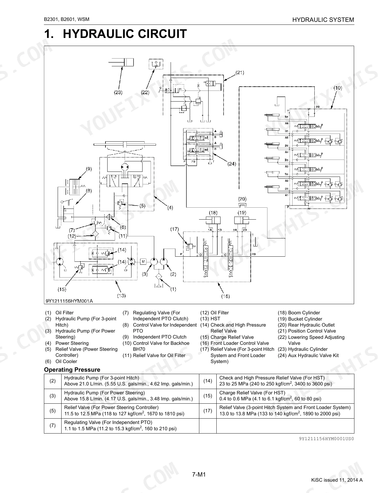
| 7 Hydraulic System | 258-297 | Front Loader Control Valve (Structure, Operation), Remote Control Valve, Hydraulic Outlet, Hydraulic Circuit, Hydraulic Pump, Checking |
| 8 Electrical System | 298-341 | Wiring Diagram, Engine Starting System And Stopping System (Opc System Circuit, Controller, Safety Switch, Starter, Engine Stop Solenoid, Glow Plug), Charging System |
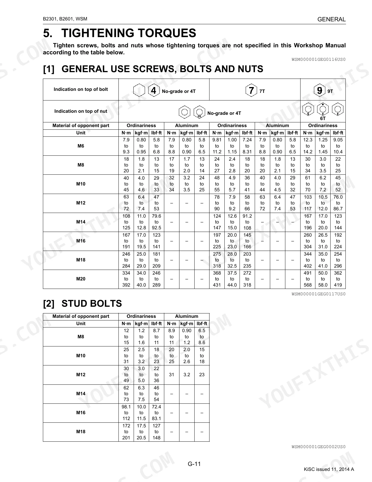
Every system also includes tightening torques, and troubleshooting.
Quick Reference Specifications
| Specification | Value | Page |
|---|---|---|
| All Models | ||
| Rear wheel mounting nut Tightening torque | 145 to 150 N·m | p. 35 |
| Front loader valve pipe joint bolt Tightening torque | 48 to 70 N·m | p. 163 |
| Fuel filter element Replacement Interval | every 400 Hr | p. 28 |
| Air cleaner element [Primary element] Replacement Interval | every 1 year | p. 28 |
| Hydraulic oil filter Replacement Interval | every 400 Hr | p. 28 |
| Fuel line Replacement Interval | every 2 years | p. 28 |
| Battery terminal Greasing Type | Multipurpose type grease NLGI-2 or NLGI-1 (GC-LB) | p. 23 |
| Fan belt tension | A deflection of between 7.0 to 9.0 mm | p. 39 |
| Brake Pedal Free Travel | 30 to 40 mm | p. 216 |
| Charge pressure | 0.4 to 0.6 MPa | p. 164 |
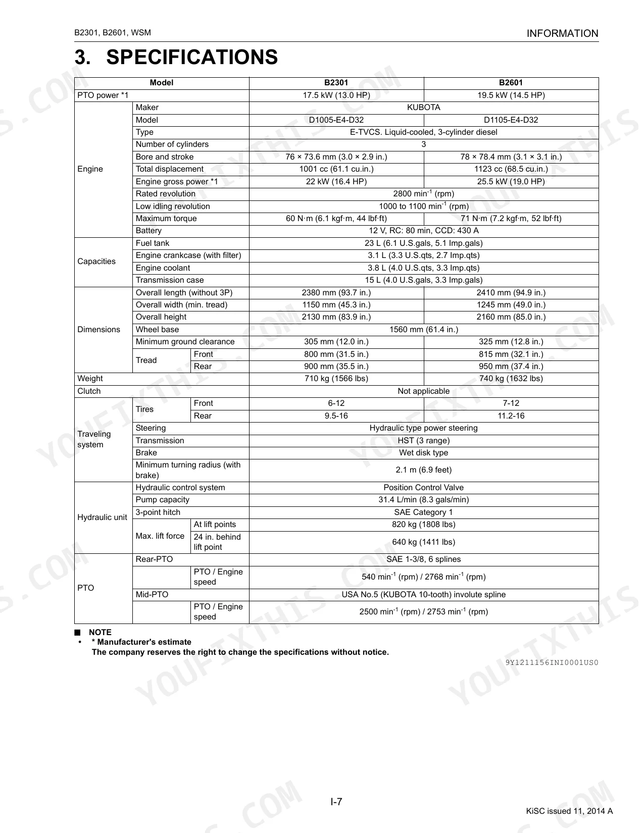
| B2301 | ||
| PTO Power | 17.5 kW (13.0 HP) | p. 11 |
| B2601 | ||
| PTO Power | 19.5 kW (14.5 HP) | p. 11 |
Kubota B2301, B2601 Common Problems This Manual Covers
Kubota B2301/B2601 engine starts then dies, stumbles, or requires repeated cranking after fuel filter or hose service
Check the fuel bowl and bleed screws for trapped air before attempting a cold start. Crack the bleed screw at the fuel filter housing and crank until bubble-free fuel flows, then snug it closed. Replace the fuel filter element at the 400-hour interval per page 28. Inspect all fuel lines and clamps for cracking or seepage; Kubota specifies line replacement every 2 years regardless of appearance.
Manual Section: 1 EngineHydraulic implements respond slowly, won't reach full height, or loader feels weak under load p. 279
Verify transmission case fluid level first; capacity is 15 L, and low fluid is the most common cause. Check the hydraulic oil filter, which is due for replacement every 400 hours (page 28). With the system warm, measure charge pressure at the test port: spec is 0.4 to 0.6 MPa (page 164). If pressure is low, inspect the suction line for air ingestion before assuming a pump failure.
Manual Section: 7 Hydraulic SystemBrake pedal sinks too far, feels spongy, or tractor pulls to one side during stops p. 216
Measure brake pedal free travel before any adjustment: correct range is 30 to 40 mm at the pedal pad (page 216). If travel is outside spec, adjust both sides equally using the linkage adjuster nuts in the Brakes section. Uneven adjustment between left and right pedals is the leading cause of drift on braking. Recheck free travel on both pedals before returning the tractor to service.
Manual Section: 4 BrakesStarter cranks slowly or not at all, electrical equipment intermittently dead or unresponsive p. 315
Test battery voltage under load before condemning the starter. A surface-charged battery can read 12.6 V at rest but collapse under cranking. Clean both battery terminals, then coat them with multipurpose grease NLGI-2 or NLGI-1 (GC-LB) per page 23 to prevent corrosion. Inspect every connector in the starting circuit for spread terminals or green oxidation. The troubleshooting chart starting at page 315 walks the complete starting circuit, including the OPC safety switch logic.
Manual Section: 8 Electrical SystemEngine overheats under load or coolant temperature gauge climbs above normal range
Compare coolant level against the 3.8 L system capacity, then inspect the radiator screen for chaff or debris (a blocked screen is the most common field cause of heat buildup). Verify fan belt tension: correct deflection is 7.0 to 9.0 mm at mid-span (page 39). If coolant and airflow both check out, move to the engine troubleshooting chart, which covers overheating diagnosis including thermostat and water pump checks.
Manual Section: 1 EngineHST transmission loses drive power progressively, vibrates, or oil overheats during field operation
Confirm transmission case fluid is at the full mark (15 L capacity) and that the hydraulic oil filter was replaced at the last 400-hour service (page 28). With oil at operating temperature, check charge pressure at the HST test port: 0.4 to 0.6 MPa is the specification (page 164). If pressure is within spec but power loss persists, consult the HST troubleshooting table for control linkage and valve diagnostics.
Manual Section: 2 TransmissionFrequently Asked Questions
How do I reset the HST pedal or range selector on a Kubota B2601?
To adjust the HST neutral position, lift the rear wheels and loosen the neutral adjuster setting screw. Rotate the adjuster clockwise until wheels turn in reverse, then counterclockwise until they stop. Repeat for forward motion. Place a mark at each stop point and set the adjuster groove in the middle of the marks before tightening the screw.
What is the torque spec for the Kubota B2301/B2601 wheel bolts?
The tightening torque for the front wheel mounting nuts is 78 to 90 N·m (58 to 66 lbf·ft). For the rear wheel mounting nuts, the specified torque is 145 to 150 N·m (107 to 110 lbf·ft). Check bolts and nuts frequently, especially when new, and keep them tight.
Kubota B2301 torque specs for wheel bolts
Front wheel mounting nuts call for 78 to 90 N·m (58 to 66 lbf·ft), while the rear wheel mounting nuts take 145 to 150 N·m (107 to 110 lbf·ft). Recheck the wheel hardware on a regular basis to keep these nuts tight.
What are the replacement specifications for fuel filter element?
The fuel filter element should be cleaned every 100 hours of operation. It must be replaced every 400 hours. The cleaning procedure is detailed on page G-24 of the manual.
How quickly can I access this Kubota B2301, B2601 manual after buying?
A 341-page Shop Manual in searchable PDF format, available the moment you complete checkout. View it on a computer, tablet, or phone, with no shipping wait.
Is this Kubota B2301, B2601 Shop Manual printable?
None at all. The PDF is DRM-free, so print whatever sections you want to take out to the shop. Standard letter or A4 paper works.
Are hydraulic system diagrams in this Kubota B2301, B2601 Shop Manual?
Yes. Complete hydraulic schematics with flow diagrams, valve configurations, and pressure specifications are included.
Document Quality
This is a native digital PDF, not a scanned document, so the full text is searchable and you can easily copy and paste content. The text is sharp and easy to read, while the diagrams are a mix of crisp vector line drawings and clear grayscale photographs; all labels and callouts are legible. All pages are clean and well-formatted, without any scan artifacts, marks, or skewed content.


Reviews
There are no reviews yet.