


This Kubota B2400HSE Parts Catalog PDF maps every component on your HSE-spec tractor across 255 pages, from crankcase internals to ROPS hardware. The 125 pages of exploded-view parts lists span engine, fuel system, cooling, electrical, drivetrain, steering, and hydraulic component diagrams, while hydraulic parts diagrams trace fluid routing through the pump, control valve, HST loop, oil cooler line, and steering cylinder. Every listing carries Kubota factory part numbers with quantity callouts, serial-number applicability breakpoints, and country-code cross-references for the AU, CA, and GR market variants. Ordering pistons? The catalog separates STD from oversized options and identifies each fuse by exact amperage: 5A, 10A, and 15A auto fuses plus the 30A main. A wrong part means a second trip to the dealer. Download it, bookmark your system, and have the right number before you pick up the phone.
What's Inside This Kubota B2400HSE Parts Manual
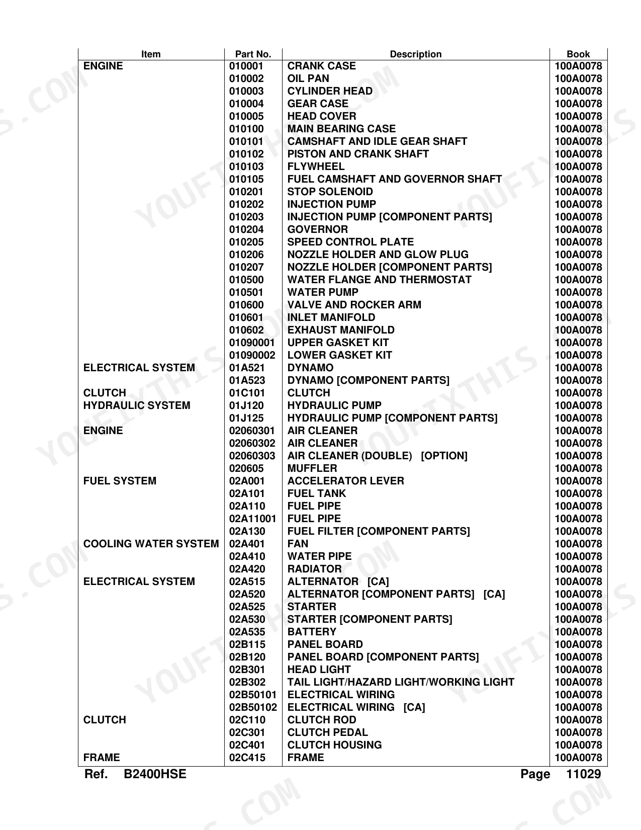
| System | Pages |
|---|---|
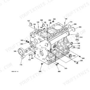
| Crank Case | 6-7 |
| Oil Pan | 8-10 |
| Cylinder Head | 11-12 |
| Gear Case | 13-14 |
| Head Cover | 15-16 |
| Main Bearing Case | 17-18 |
| Camshaft and Idle Gear Shaft | 19-20 |
| Piston and Crank Shaft | 21-22 |
| Flywheel | 23-24 |
| Fuel Camshaft and Governor Shaft | 25-26 |
| Stop Solenoid | 27-29 |
| Injection Pump | 30-31 |
| Injection Pump [Component Parts] | 32-33 |
| Governor | 34-36 |
| Speed Control Plate | 37-38 |
| Nozzle Holder and Glow Plug | 39-41 |
| Nozzle Holder [Component Parts] | 42-43 |
| Water Flange and Thermostat | 44-46 |
| Water Pump | 47-48 |
| Valve and Rocker Arm | 49-51 |
| Inlet Manifold | 52-53 |
| Exhaust Manifold | 54-55 |
| Upper Gasket Kit | 56-57 |
| Lower Gasket Kit | 58-59 |
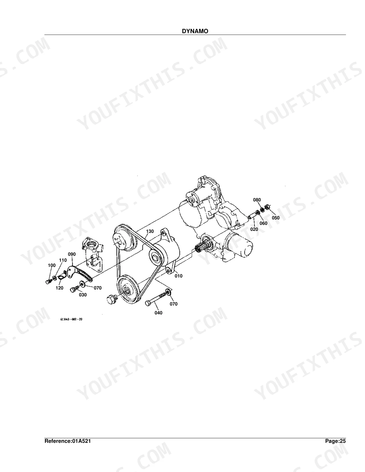
| Dynamo | 60-61 |
| Dynamo [Component Parts] | 62-63 |
| Clutch | 64-65 |
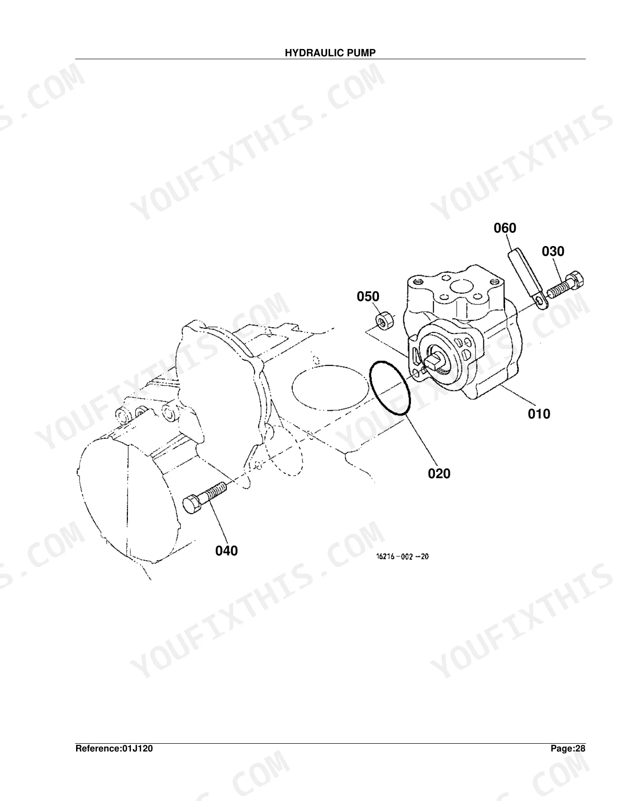
| Hydraulic Pump | 66-67 |
| Hydraulic Pump [Component Parts] | 68-70 |
| Air Cleaner | 71-74 |
| Air Cleaner (Double) [Option] | 75-76 |
| Muffler | 77-78 |
| Accelerator Lever | 79-80 |
| Fuel Tank | 81-83 |
| Fuel Pipe | 84-87 |
| Fuel Filter [Component Parts] | 88-89 |
| Fan | 90-91 |
| Water Pipe | 92-93 |
| Radiator | 94-95 |
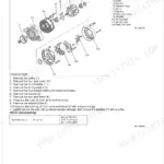
| Alternator [CA] | 96-97 |
| Alternator [Component Parts] [CA] | 98-99 |
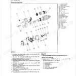
| Starter | 100-101 |
| Starter [Component Parts] | 102-103 |
| Battery | 104-105 |
| Panel Board | 106-107 |
| Panel Board [Component Parts] | 108-109 |
| Head Light | 110-111 |
| Tail Light/Hazard Light/Working Light | 112-113 |
| Electrical Wiring | 114-115 |
| Electrical Wiring [CA] | 116-117 |
| Clutch Rod | 118-119 |
| Clutch Pedal | 120-121 |
| Clutch Housing | 122-124 |
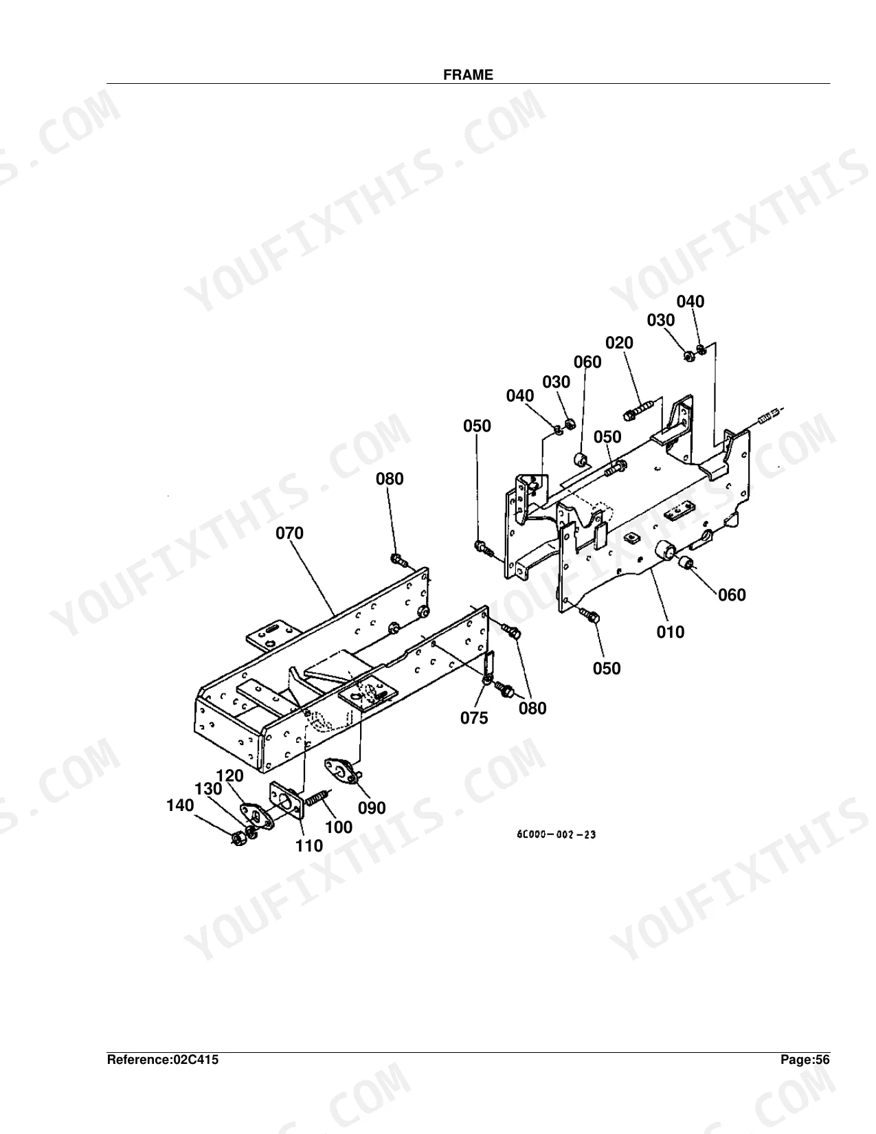
| Frame | 125-126 |
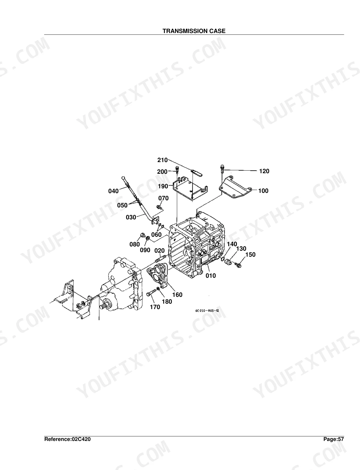
| Transmission Case | 127-128 |
| Differential Gear Case | 129-130 |
| Rear Axle Case | 131-132 |
| Clutch Shaft/Propeller Shaft | 133-134 |
| HST | 135-136 |
| HST [Component Parts] | 137-140 |
| 2nd Shaft/3rd Shaft/4th Shaft | 141-143 |
| 5th Shaft/PTO Shaft | 144-146 |
| Mid PTO | 147-148 |
| Rear Differential | 149-150 |
| Rear Axle | 151-152 |
| Brake | 153-154 |
| Parking Brake Lever | 155-156 |
| Speed Change Lever | 157-158 |
| Speed Control Pedal | 159-160 |
| Speed Set Lever | 161-162 |
| Range Gear Shift Lever | 163-164 |
| Front Wheel Drive Lever Plug | 165-166 |
| PTO Gear Shift Lever | 167-169 |
| Position Control Lever | 170-172 |
| Brake Pedal | 173-174 |
| Differential Lock Pedal | 175-176 |
| Front Axle Frame | 177-178 |
| Front Wheel Hub | 179-180 |
| Drag Link/Tie Rod | 181-182 |
| Steering Handle | 183-185 |
| Steering Controller | 186-188 |
| Steering Controller [Component Parts] | 189-194 |
| Hydraulic Oil Line (Suction) | 195-196 |
| Flow Divider Valve [Component Parts] | 197-198 |
| Hydraulic Oil Line (Steering) | 199-201 |
| Hydraulic Oil Line (T/M) | 202-203 |
| Hydraulic Oil Line (HST) | 204-205 |
| Hydraulic Oil Line (Oil Cooler) | 206-207 |
| Hydraulic Cylinder Case | 208-210 |
| Control Valve | 211-214 |
| Control Valve [Component Parts] | 215-218 |
| Lift Rod | 219-220 |
| Lower Link | 221-222 |
| Top Link | 223-224 |
| Front Grille | 225-226 |
| Hood (Bonnet) | 227-228 |
| Side Cover | 229-230 |
| Fender | 231-232 |
| Extension Fender | 233-234 |
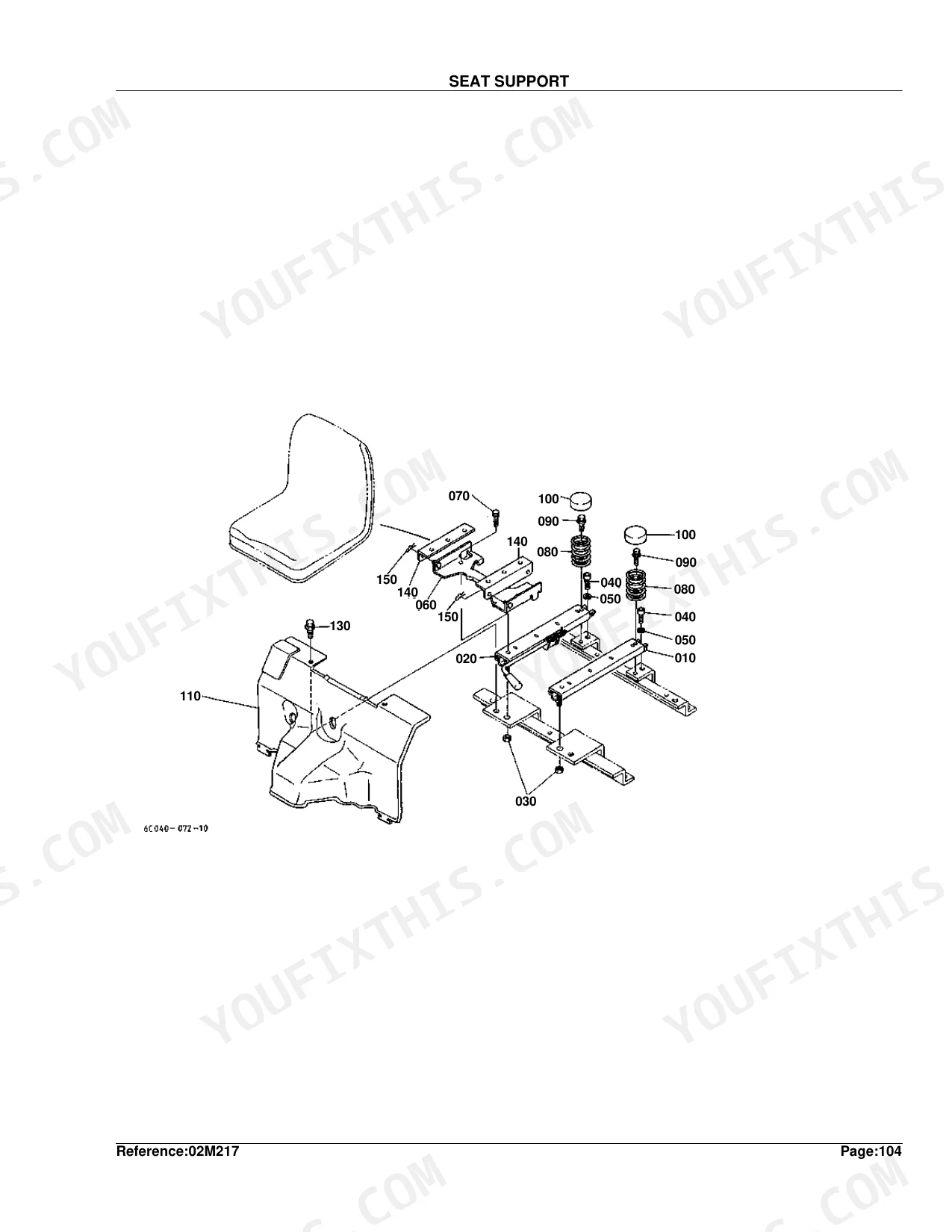
| Seat Support | 235-236 |
| Seat | 237-238 |
| Step | 239-240 |
| ROPS | 241-242 |
| Front Wheel (6.50-10) | 243-244 |
| Rear Wheel (11.2-16) | 245-246 |
| Rear Wheel (33*12.5-15) | 247-248 |
| Rear Wheel (31*15.5-15) | 249-250 |
| Label | 251-252 |
| Extension Stopper | 253-254 |
| Accessories and Service Parts | 255-255 |
Quick Reference Specifications
| Specification | Value | Page |
|---|---|---|
| FUSE AUTO replacement value | 5A | p. 115 |
| FUSE replacement value | 30A | p. 115 |
| SOLENOID STOP weight | 0.35 kgf | p. 29 |
| PISTON size | STD | p. 22 |
| ASSY PISTON RING size | STD | p. 22 |
| Injection Pump Shim Thickness (0.20MM) | 0.20MM | p. 31 |
| Injection Pump Shim Thickness (0.25MM) | 0.25MM | p. 31 |
| Injection Pump Shim Thickness (0.30MM) | 0.30MM | p. 31 |
| Nozzle Holder Washer Adjusting (0.10MM) | 0.10MM | p. 43 |
| Nozzle Holder Washer Adjusting (0.80MM) | 0.80MM | p. 43 |
| Upper Gasket Kit Weight | 0.23 kgf | p. 57 |
| Lower Gasket Kit Weight | 0 kgf | p. 59 |
Kubota B2400HSE Common Problems This Manual Covers
Kubota B2400HSE won't start or cranks without firing, need the correct fuel stop solenoid part number p. 27
Open the Stop Solenoid exploded view on page 27. The complete assembly weighs 0.35 kgf per the spec on page 29 and is listed with all sub-components across pages 27-29. Cross-reference the part number against your serial number range using the parts index before ordering, since numbers may vary by production year.
Manual Section: Stop SolenoidTractor won't start after sitting, need to identify blown fuse part numbers in the electrical system p. 114
Turn to the Electrical Wiring diagram on page 114. Page 115 lists three auto-fuse ratings on the fuse block: 5A, 10A, and 30A. On CA-spec machines, also check page 116 and page 117 for the 50A main fuse. Match each fuse slot to its circuit before ordering the replacement part number.
Manual Section: Electrical WiringEngine needs rebuilding due to compression loss, unsure which oversize piston and ring part numbers apply p. 21
Pull up the Piston and Crank Shaft exploded view on page 21. Verify the sizes you need against page 22: pistons and piston ring assemblies come in STD and +0.50MM oversize, and crankpin bearings in STD, -0.20MM, and -0.40MM undersize sets. Measure your bore and journal first, then order by the correct size designation.
Manual Section: Piston and Crank ShaftInjection pump removed for service, need to identify correct shim part numbers and available thicknesses p. 30
Check the Injection Pump parts list on page 30. Page 31 stocks shims in three thicknesses, 0.20MM, 0.25MM, and 0.30MM, each with a distinct part number. Cross-reference the component parts exploded view on page 32 to confirm how many shims your pump takes and which position they occupy before ordering.
Manual Section: Injection PumpCylinder head gasket failed, need to confirm which gasket kit covers the full engine head set p. 56
Compare the Upper Gasket Kit exploded view on page 56 against your engine serial range, confirming the kit weight of 0.23 kgf listed on page 57. For bottom-end gaskets, locate the Lower Gasket Kit on page 58. Order both kits together on a full overhaul to cover every sealing surface.
Manual Section: Upper Gasket KitFrequently Asked Questions
What are the replacement specifications for fuses?
The manual lists several fuse specifications for replacement. For the standard electrical wiring, fuses include a 30A fuse (Part No. 1G111-65720), 5A auto fuses (Part No. 66426-80010), a 10A auto fuse (Part No. 36730-75550), and a 15A auto fuse (Part No. 35820-75560). For the [CA] electrical wiring, there is a 50A fuse (Part No. 17478-60080), along with the same 5A, 10A, and 15A auto fuses.
How quickly can I access this Kubota B2400HSE manual after buying?
A 255-page Parts Catalog in searchable PDF format, available the moment you complete checkout. View on computer, tablet, or phone — no shipping wait.
Is this Kubota B2400HSE Parts Catalog printable?
Yes. The PDF has no DRM restrictions — print any page or section you need for your shop. Works with any standard printer.
Document Quality
This document is a high-quality digital PDF, allowing you to search and copy text from all pages. The text is consistently crisp and easy to read throughout the instructions and parts lists. Diagrams and illustrations are clear raster images, with all labels remaining perfectly readable. The pages are clean, free from scan artifacts, stains, or skewed content, and there are no notable blank or filler pages.


Reviews
There are no reviews yet.