


Every washer, shim, and O-ring on your B26 is mapped across 299 pages of exploded views. Crankcase, cylinder head, HST assembly, front differential, hydraulic control valve: each illustration carries the OEM callout. Roughly 40 pages cover engine internals, 30 trace the drivetrain, 20 detail hydraulic pistons and lift arms, and 25 lay out chassis and ROPS components. Cross-reference the 0.2mm relief valve shim on page 181, or pull the 40A fuse callout from the panel board on page 91. Order the wrong part once and you lose a week to a restock fee. Identify it correctly the first time. Bookmarks jump from crankcase to canopy: tap an assembly, read the number, write it down.
What's Inside This Kubota B26 Parts Manual
| System | Pages |
|---|---|
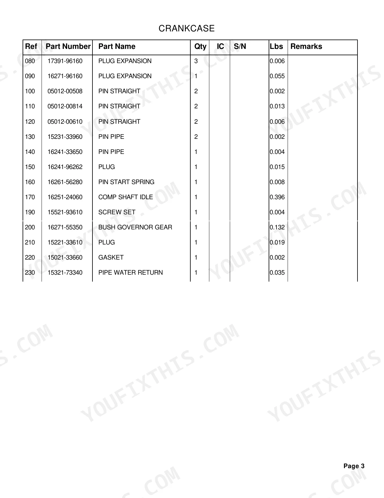
| Crankcase | 3-4 |
| Oil Pan | 5-6 |
| Cylinder Head | 7-8 |
| Gear Case | 9-10 |
| Head Cover | 11-12 |
| Oil Filter | 13-13 |
| Dipstick and Guide | 14-14 |
| Main Bearing Case | 15-16 |
| Camshaft and Idle Gear Shaft | 17-18 |
| Piston and Crankshaft | 19-21 |
| Flywheel | 22-23 |
| Fuel Camshaft and Governor Shaft | 24-25 |
| Idle Apparatus | 26-27 |
| Injection Pump | 28-29 |
| Governor | 30-31 |
| Speed Control Plate | 32-33 |
| Nozzle Holder and Glow Plug | 34-35 |
| Nozzle Holder [Component Parts] | 36-37 |
| Fuel Pump(Mechanical) | 38-38 |
| Water Flange and Thermostat | 39-40 |
| Water Pump | 41-42 |
| Valve and Rocker Arm | 43-44 |
| Inlet Manifold | 45-46 |
| Air Cleaner | 47-48 |
| Muffler | 49-50 |
| Upper Gasket Kit | 51-52 |
| Lower Gasket Kit | 53-54 |
| Accelerator Lever | 55-56 |
| Fuel Tank | 57-58 |
| Fuel Pipe | 59-60 |
| Fuel Filter [Component Parts] | 61-61 |
| Fan | 62-63 |
| Water Pipe | 64-65 |
| Radiator | 66-67 |
| Reserve Tank | 68-69 |
| Stop Solenoid | 70-70 |
| Alternator | 71-72 |
| Alternator [Component Parts] | 73-74 |
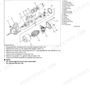
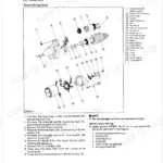
| Starter | 75-75 |
| Starter [Component Parts] | 76-77 |
| Battery | 78-79 |
| Switch | 80-81 |
| Panel Board | 82-83 |
| Panel Board [Component Parts] | 84-85 |
| Head Light | 86-86 |
| Hazard Light | 87-87 |
| Tail Light | 88-89 |
| Working Light | 90-90 |
| Electrical Wiring (Body) | 91-92 |
| Electrical Wiring (Canopy) | 93-93 |
| Clutch Housing | 94-95 |
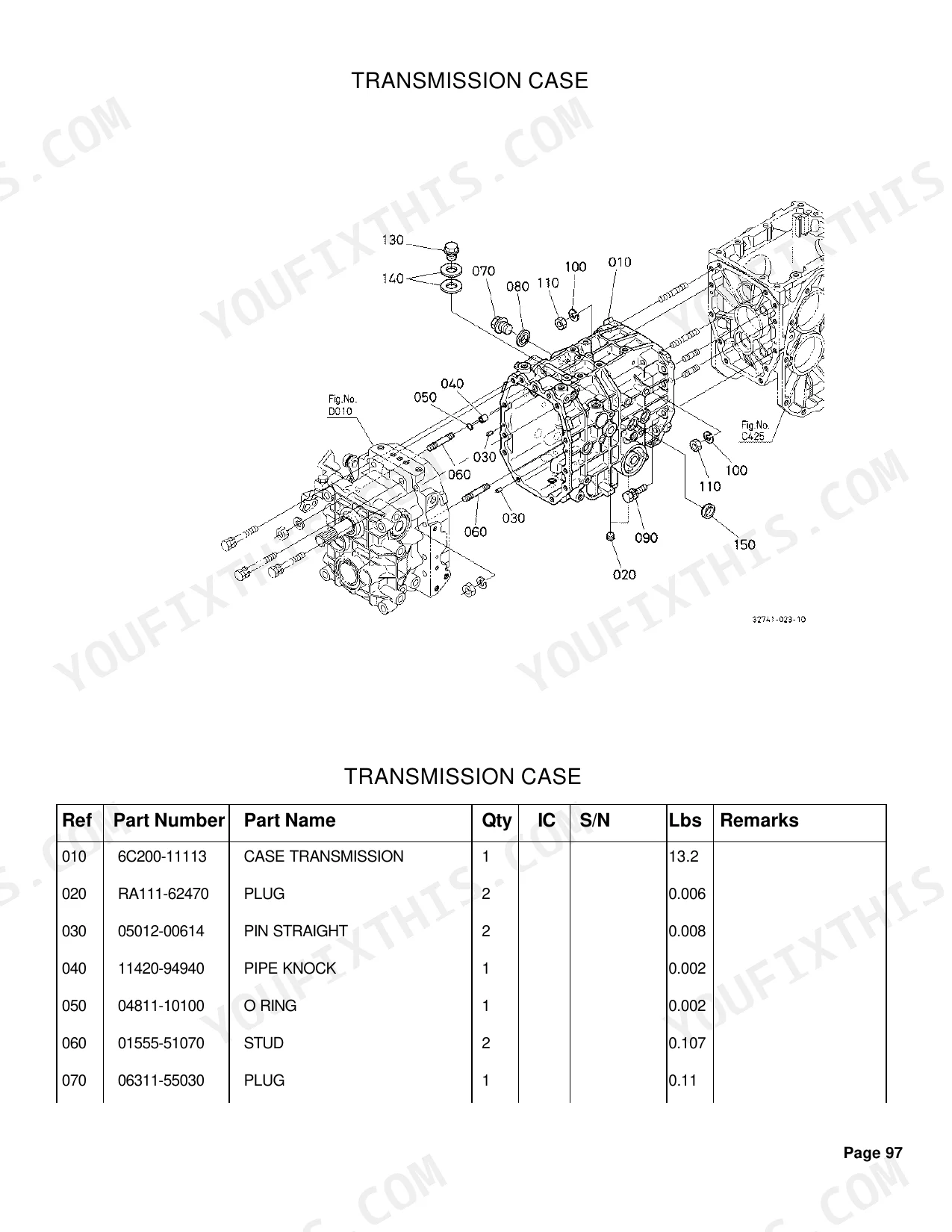
| Center Frame | 96-97 |
| Transmission Case | 98-99 |
| Differential Gear Case | 100-101 |
| Rear Axle Case Lh | 102-103 |
| Rear Axle Case Rh | 104-105 |
| Clutch Shaft | 106-106 |
| Propeller Shaft | 107-108 |
| HST | 109-110 |
| HST [Component Parts] 1 | 111-112 |
| HST [Component Parts] 2 | 113-114 |
| HST [Component Parts] 3 | 115-116 |
| HST [Component Parts] 4 | 117-118 |
| Range Gear Shaft | 119-120 |
| Reverse Shaft | 121-122 |
| PTO Counter Shaft | 123-124 |
| PTO Clutch Shaft | 125-126 |
| PTO Clutch | 127-128 |
| Bevel Gear Shaft/Range Gear | 129-130 |
| Rear Differential | 131-132 |
| Range Gear Shift Fork | 133-134 |
| Differential Lock Shift Fork | 135-135 |
| Speed Control Pedal | 136-137 |
| Range Gear Shift Lever | 138-139 |
| Front Wheel Drive Lever | 140-141 |
| PTO Gear Shift Lever | 142-142 |
| Rear Axle | 143-143 |
| Differential Lock Pedal | 144-144 |
| Brake | 145-146 |
| Brake Rod | 147-148 |
| Parking Brake Lever | 149-151 |
| Brake Pedal | 152-153 |
| Position Control Lever | 154-155 |
| Hydraulic Pump | 156-156 |
| Hydraulic Pump [Component Parts] | 157-158 |
| Oil Tank | 159-160 |
| Hydraulic Oil Line(Suction) | 161-161 |
| Hydraulic Oil Line(Steering) | 163-164 |
| Hydraulic Oil Line(Backhoe) | 165-166 |
| Hydraulic Oil Line (HST) | 167-168 |
| Hydraulic Oil Line (Oil Cooler) | 169-170 |
| Hydraulic Cylinder | 171-172 |
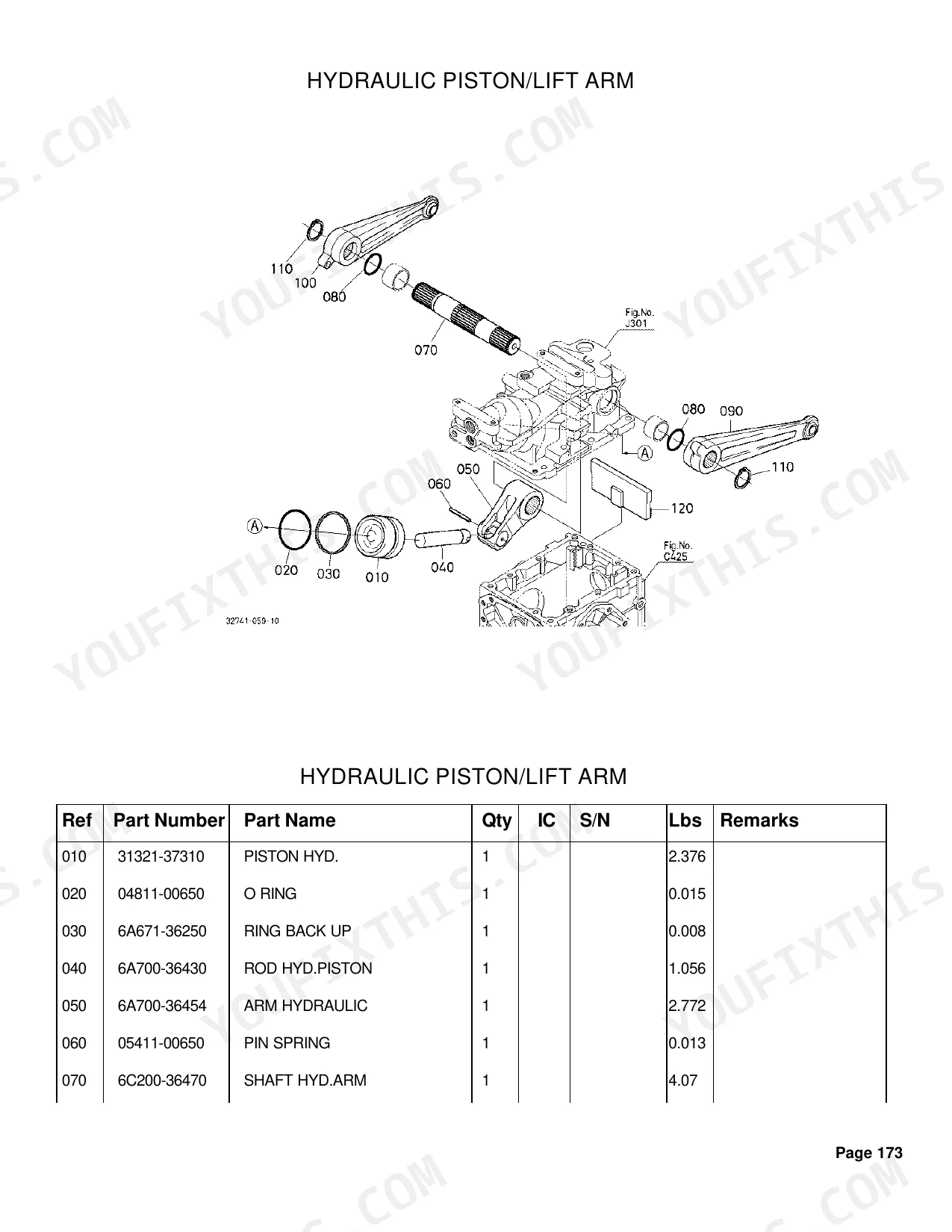
| Hydraulic Piston/Lift Arm | 173-174 |
| Feed Back Lever | 175-176 |
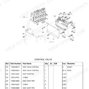
| Control Valve | 177-178 |
| Control Valve [Component Parts] | 179-180 |
| Safety Valve | 181-182 |
| Hydraulic Outlet | 183-187 |
| Hydraulic Outlet [Component Parts] | 186-186 |
| PTO Valve | 188-189 |
| PTO Valve [Component Parts] | 190-191 |
| 3-Point Linkage (Lift Rod) | 192-193 |
| Front Axle Frame | 194-194 |
| Front Axle Case | 195-196, 202 |
| Front Differential | 197-198 |
| Differential Gear Shaft | 199-200 |
| Bevel Gear Case | 201-201 |
| Front Axle | 204-205 |
| Front Drive Shaft | 206-207 |
| Steering Handle | 208-209 |
| Steering Post | 210-211 |
| Tilt Pedal | 212-214 |
| Steering Controller | 215-215 |
| Steering Linkage | 216-217 |
| Steering Cylinder [Component Parts] | 218-218 |
| Lower Link | 219-220 |
| 3-Point Linkage (Top Link) | 221-222 |
| Check Chain | 223-224 |
| Hitch | 225-225 |
| PTO Protector | 226-227 |
| Front Grille | 228-229 |
| Bonnet | 230-231 |
| Panel Cover | 232-232 |
| Side Cover | 233-234 |
| Shutter Plate | 235-236 |
| Lever Guide Lh | 237-238 |
| Lever Guide Rh | 239-240 |
| Fender | 241-242 |
| Floor Sheet | 243-245 |
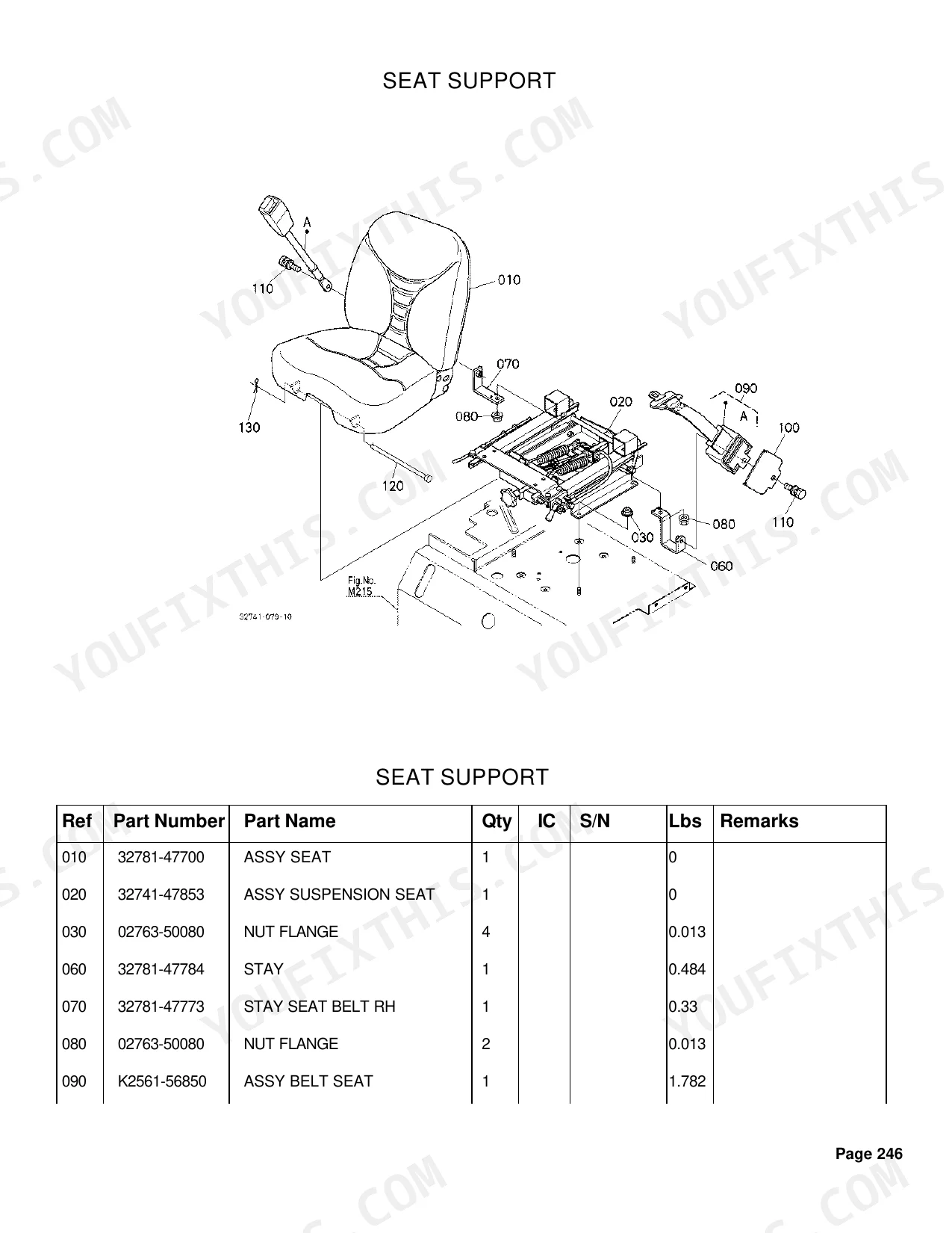
| Seat Support | 246-247 |
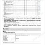
Quick Reference Specifications
| Specification | Value | Page |
|---|---|---|
| Shim Thickness | 0.2mm | p. 181 |
| Fuse Rating | 40A | p. 91 |
| Piston Oversize | 0.50mm | p. 19 |
| Shim Injection Pump Thickness | 0.300mm | p. 28 |
| Washer Adjusting Thickness | 0.20mm | p. 37 |
| Battery Type | 55B24L | p. 78 |
| Panel Board Lamp Wattage | 1.7W | p. 84 |
| Head Light Bulb Wattage | 35W | p. 86 |
| Fuse Amperage | 40A | p. 91 |
| Gear Teeth, Range Gear | 26T | p. 119 |
| Gear Teeth, Bevel Gear Shaft | 17T | p. 129 |
| Gear Teeth, Gear Bevel | 12T | p. 131 |
Kubota B26 Common Problems This Manual Covers
Kubota B26 fuel shutoff solenoid part number lookup for crank-no-start diagnosis p. 70
Open the Stop Solenoid exploded view on page 70 and match callout numbers against your unit. Cross-reference the solenoid body and the two terminal leads to your serial range before ordering. Verify the 40A main fuse on page 91 is the correct replacement, since a blown fuse mimics a dead solenoid.
Manual Section: Stop SolenoidNeed correct shim thickness and part number for the hydraulic relief valve in the safety valve assembly p. 181
Reference the Safety Valve diagram on page 181. Two adjusting shims are listed, 0.2mm and 0.3mm, stacked under the spring seat to set relief pressure. Count existing shims before ordering and pull both thicknesses so the original stack can be matched on reassembly. Component parts callouts continue on page 182.
Manual Section: Safety ValveHydraulic pump exploded view needed to identify drive gear, body, and seal kit part numbers p. 156
Start with the Hydraulic Pump assembly on page 156, then move to Hydraulic Pump Component Parts on page 157 for the internal gear set, shaft, and O-rings. Match callout numbers to the parts list before ordering individual seals, since the pump is sold both as a complete assembly and as serviceable internals.
Manual Section: Hydraulic PumpFuel filter element and inline fuel pipe fittings part numbers for routine service p. 61
Pull the Fuel Filter Component Parts callouts on page 61 for the bowl, element, and O-ring. Cross-reference the Fuel Pipe diagram on page 59 for banjo bolts, sealing washers, and hose clamps from tank to injection pump. Order the element with both copper washers, since washers are not reusable.
Manual Section: Fuel Filter [Component Parts]Seat safety switch and key switch part numbers needed when tractor refuses to crank p. 80
Check the Switch group on page 80 for key switch and safety interlock part callouts, then verify the seat-side wiring on the Electrical Wiring (Body) diagram starting page 91. The 40A main fuse and inline fuses are also listed on page 91, useful when the no-crank trace points to a blown supply leg rather than a switch.
Manual Section: SwitchHST internal parts identification for transmission engagement and drive response complaints p. 109
Begin with the HST assembly overview on page 109, then walk through Component Parts pages 111, 113, 115, and 117 to identify the swash plate, charge pump, and pistons. Match the suction line fittings to the Hydraulic Oil Line (HST) callouts on page 167 before ordering, since hose ends differ by serial range.
Manual Section: HSTFrequently Asked Questions
What are the replacement specifications for Fuel filter?
Fuel filter assembly is part number 6A320-58862. The filter element itself is 6A320-59930. The assembly also includes a cup (6A320-59920) and two O-rings (6A320-59940 and 6A320-59950).
What are the replacement specifications for Air filter?
Air cleaner assembly is 6C095-58200. The main filter element assembly is 6C060-99410, and the inner element is 32721-58242.
How will I receive this Kubota B26 Parts Manual?
Immediate download of the complete 299-page searchable Parts Manual. Open it on any device, laptop at your desk or phone in the field.
Can I print this Kubota B26 manual?
Yes. No DRM or copy protection. Print the entire manual or only the pages you need on any home or office printer.
Are hydraulic system diagrams in this Kubota B26 Parts Manual?
Yes. Full hydraulic system diagrams are included, covering circuits, valve locations, and hydraulic component specs for the B26.
Document Quality
This is a native digital PDF, not a scanned document, and the full text is searchable and can be copied. The text in the parts tables is sharp and easy to read. The exploded-view diagrams are clear raster images with legible reference numbers, though they will pixelate when zoomed in closely. The pages are clean and free of any marks or scan artifacts, but you will find several blank pages throughout the document which appear to be intentional fillers.

Reviews
There are no reviews yet.