
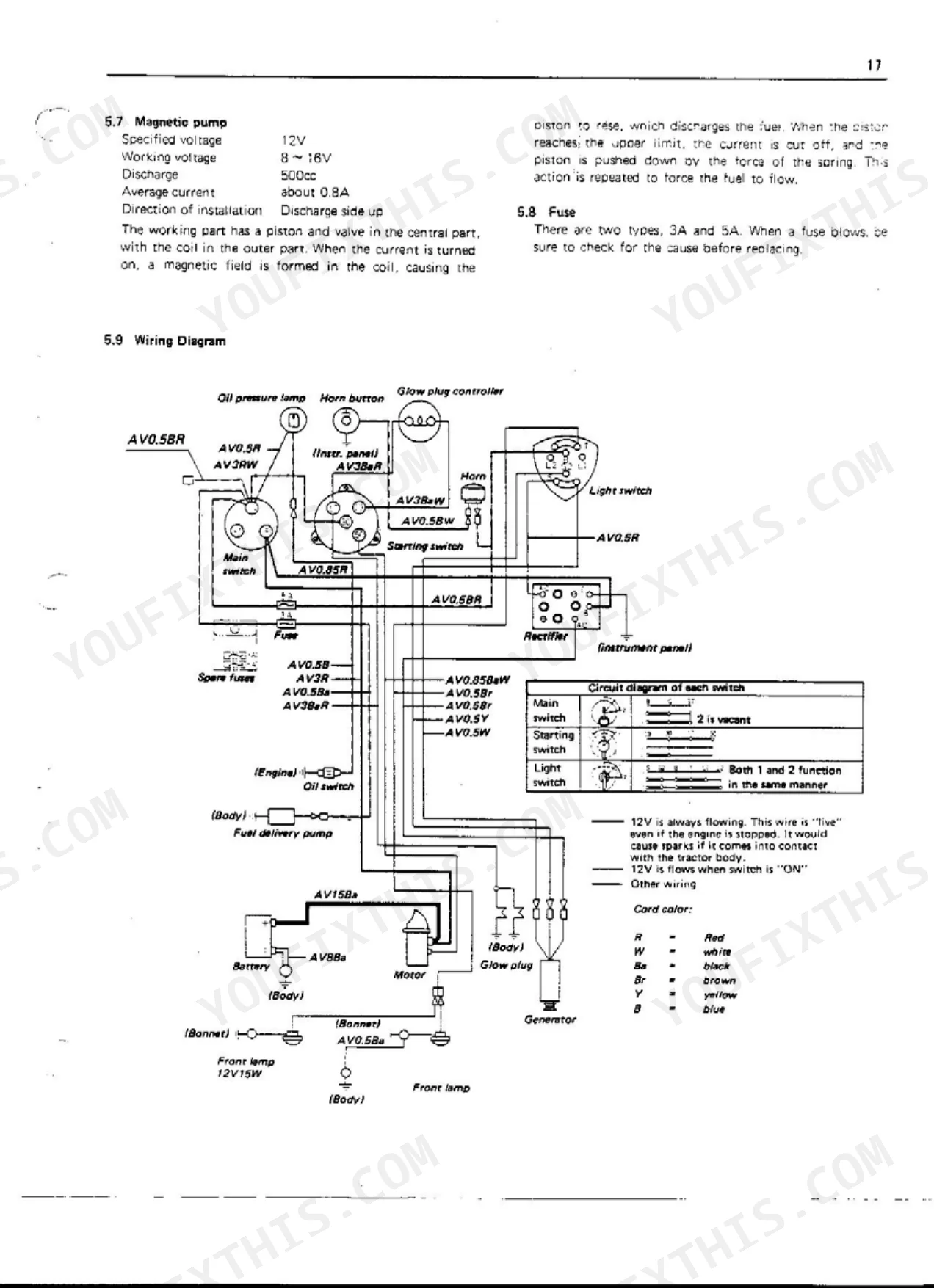
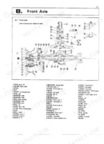
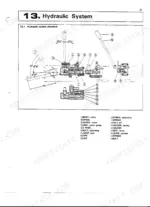
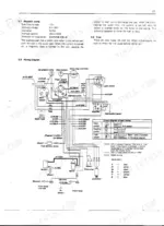
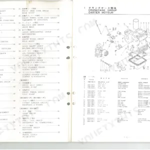
Kubota built the B6000, B6000E, and B6000E-T around the ZL600 two-cylinder diesel, and this 52-page factory manual (OEM #70000-70168) stays on those three machines. The wiring diagram traces the battery, starter, generator, rectifier, and magnetic pump circuit; separate hydraulic schematics map the lift, control valve, pump, and cylinder from end to end. Nine exploded views cover front axle teardown, transmission internals, the clutch, steering gear case, and three-point hitch assembly. Torque values are here too: cylinder head nuts at 6~6.5 kg-m, clutch pedal play of 2.5 to 3 mm, and a hydraulic oil filter swap every 100 hours. When your machine is down, you want the factory numbers, not a forum guess. Bookmarks and full-text search let you open the file on a tablet and jump straight to the section you need.
What's Inside This Kubota B6000, B6000E, B6000E-T Manual
| System | Pages | Key Topics |
|---|---|---|
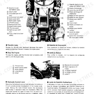
| Outside Views | 3-3 | Acceleration Lever, Hydraulic Control Lever, Brake Pedal |
| Features | 4-4 | Compact And Powerful 2-Cylinder Diesel Engine !, Unique Spherical Combustion Chamber!, Starts Up At Once By Battery-Starter! |
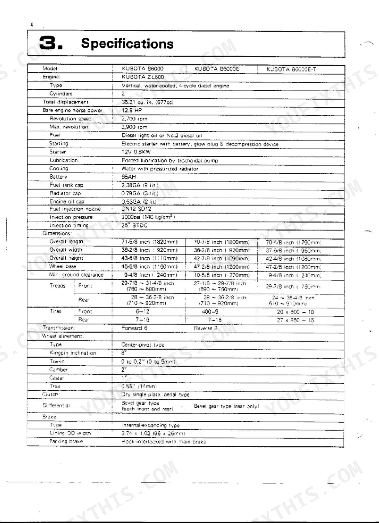
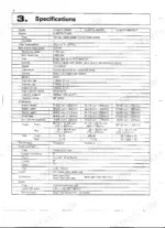
| Specifications | 5-6 | Engine Specifications, Dimensions, Transmission Specifications, Traveling Speeds |
| Engine | 7-15 | Performance Curve of KUBOTA Model ZL600 Diesel Engine, Fuel System, Lubrication System, Combustion System, Top Clearance, Air Cleaner, Main Component Parts, Idling Adjustment |
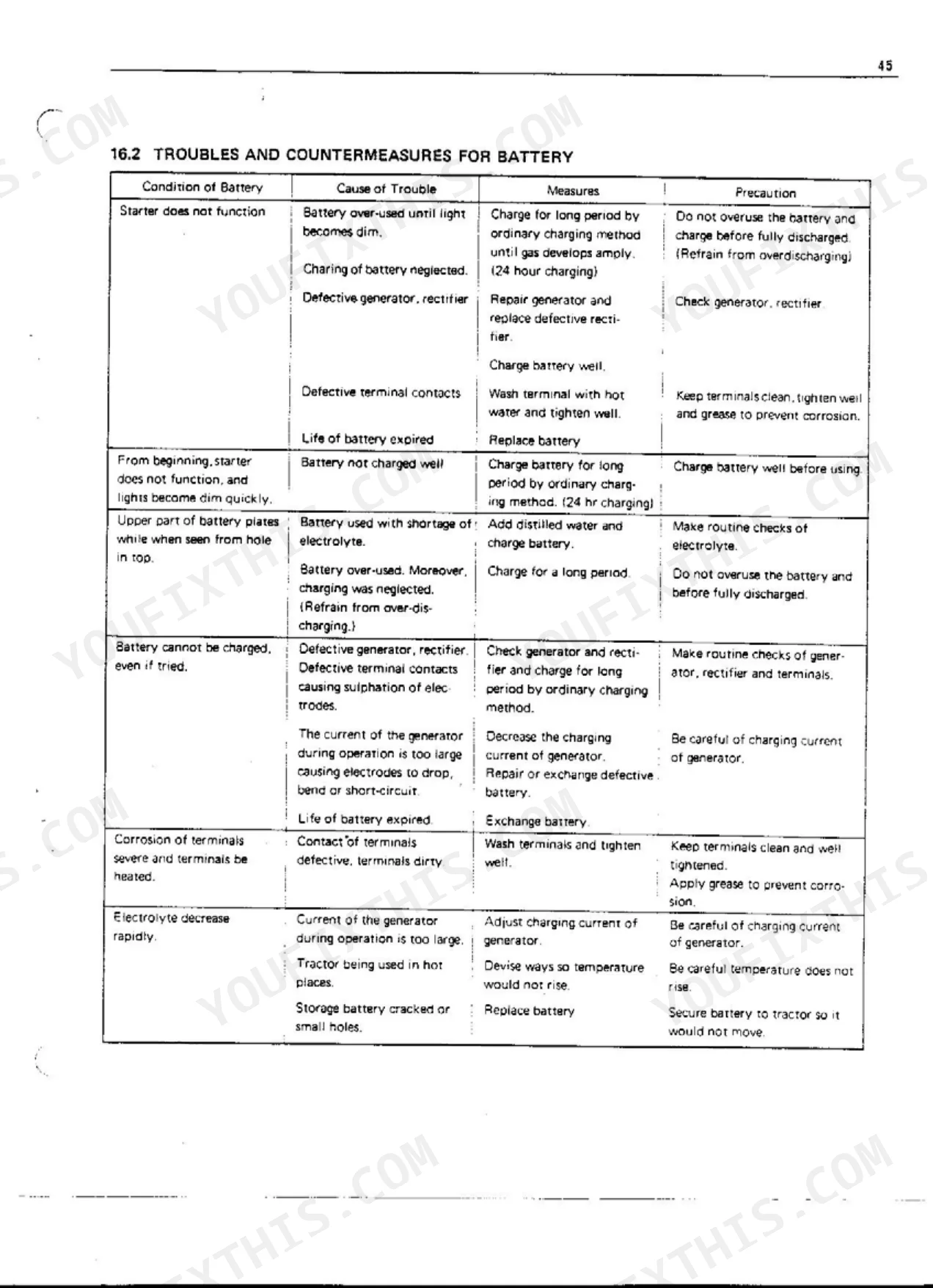
| Battery | 16-18 | Checks and Repair of Battery, Starter, Magnetic Pump |
| Tractor | 19-20 | General Precautions, Outer Appearance |
| Disassembly of Main Parts | 21-21 | Removal Of The Front Axle, Removal Of Engine, Disassembly Of Brakes, Disassembly Of Pedals, Disassembly Of Frame Clutch Housing, Seat Control Rod And Lift Arm |
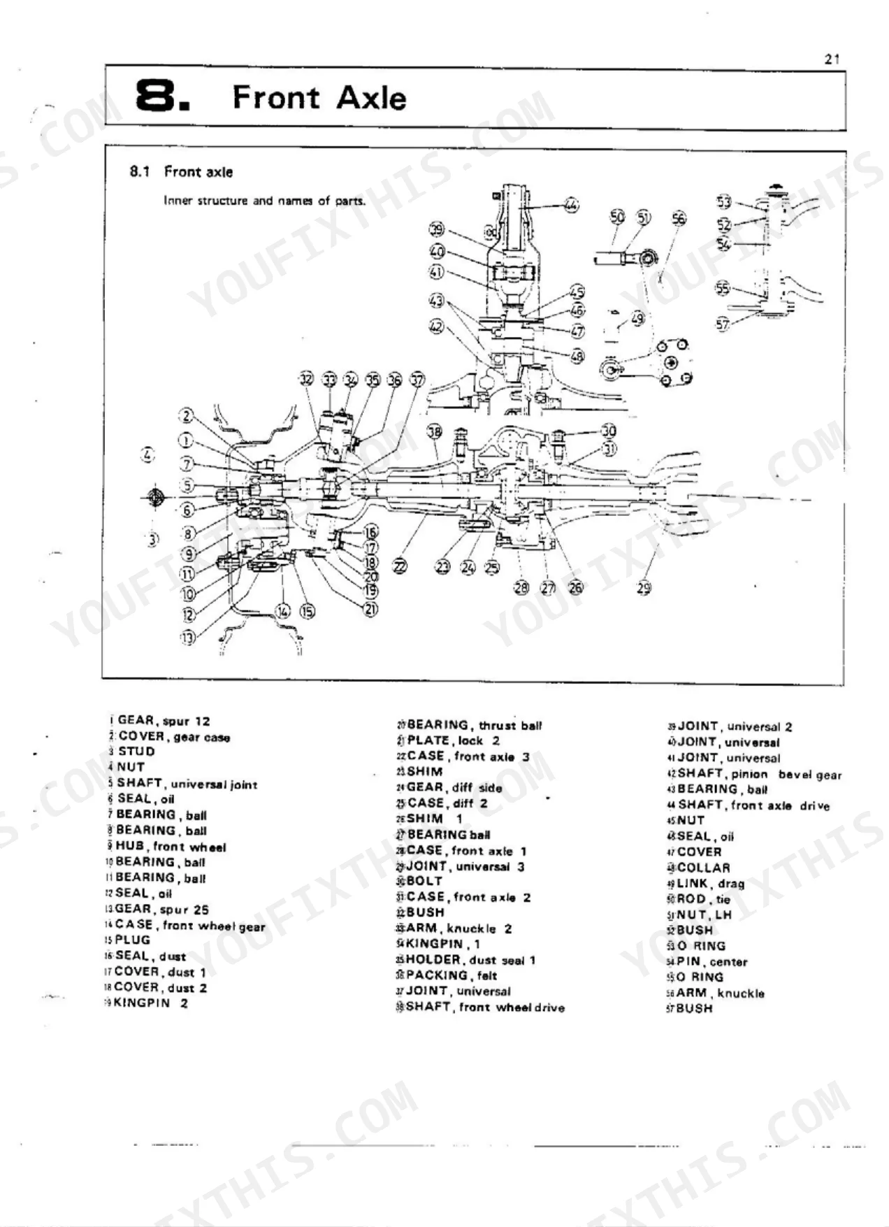
| Front Axle | 22-25 | Front Axle Inner Structure And Names Of Parts, Front Axle Structure And Nomenclature, Disassembly And Assembly |
| Steering Handle | 26-27 | Structure Of Steering Handle, Steering Gear Case, Steering Wheel, Steering Shaft, Sector Shaft, Pitman Arm |
| Clutch | 28-30 | Clutch Pedal, Brake Pedal, Clutch Adjustments, Differential Lock Pedal |
| Transmission | 31-35 | Transmission Inner Structure and Name of Parts B6000, Transmission Inner Structure and Name of Parts B6000E, Differential Gear and Rear Axle Inner Structure and Name of Parts |
| Speed Change | 36-37 | Speed Change Gear Structure for B6000, Speed Change Component Identification, Speed Change Gear Structure for B6000E |
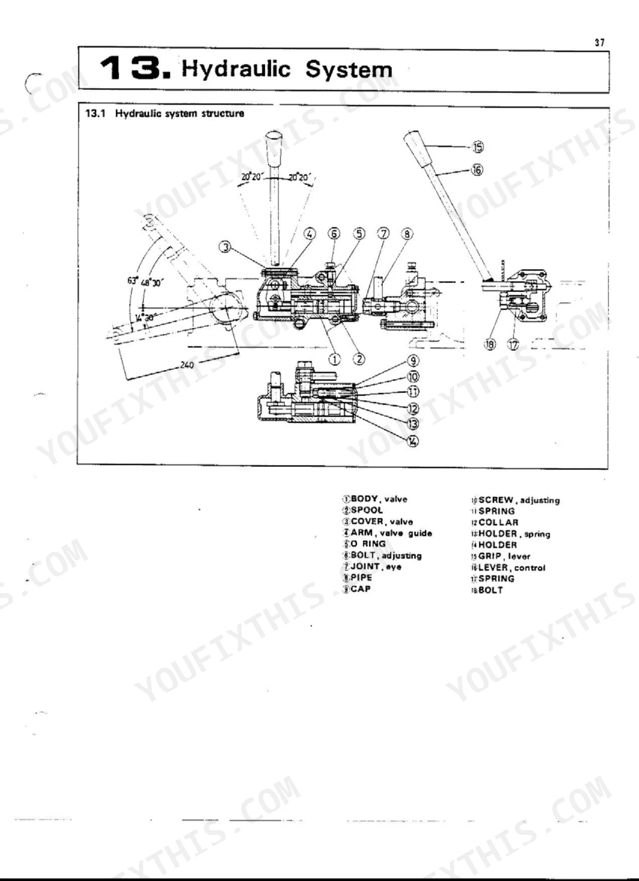
| Hydraulic System | 38-40 | Hydraulic System Structure, Hydraulic Lift, Control Valve |
| PTO | 41-41 | PTO Shaft Diagram, PTO Shaft RPM, PTO Shaft Specifications |
| Three-Point Hitch | 42-43 | Attaching of 3-Point Hitch, Three-Point Hitch Components Overview, 3-Point Hitch (Adjustment by Upper Link, Adjustment by Lift Rod, Check Chains) |
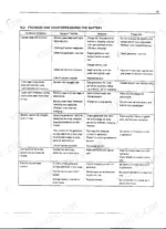
| Maintenance and Check-List | 44-47 | Troubles and Countermeasures for Battery, Troubles and Countermeasures for Engine |
| Tractor Maintenance Standard | 48-52 | Front Wheel Alignment Specifications, Front Axle Specifications, Steering Specifications, Brakes Specifications, Main Clutch Specifications, Propeller Shaft Specifications |
Quick Reference Specifications
| Specification | Value | Page |
|---|---|---|
| Clutch pedal play (initial setting) | 0.098 to 0.12 in (2.5 to 3 mm) | p. 30 |
| Implement lift cheek rod length (adjustment) | 118mm | p. 39 |
| Implement lift large hole play (adjustment) | 30mm Play | p. 39 |
| Cylinder head nut tightening torque | 6~6.5 kg-m | p. 13 |
| Hydraulic oil filter replacement/cleaning frequency | Every 100hrs. | p. 45 |
| Hydraulic oil type | high quality #80 gear oil | p. 39 |
| Hydraulic oil capacity (transmission case oil) | 2.38GA (9 lit.) | p. 45 |
| Differential bevel gear backlash (general) | 0.13~0.25 mm | p. 34 |
| Backlash of diff Pinion and diff side gear | 0.0079~0.01 in (0.20~0.25mm) | p. 50 |
| Front axle drive shaft lubrication | about 40 grams of chassis grease | p. 23 |
| Front axle drive shaft universal joint type | Universal joint 1 is welded on. | p. 23 |
| PTO shaft location | Transmission case rear center | p. 6 |
Kubota B6000, B6000E, B6000E-T Common Problems This Manual Covers
Kubota B6000 hydraulic system weak or won't lift implements after fluid service p. 39
Drain and refill the transmission case with high quality #80 gear oil to 2.38 GA (9 lit.). Clean or replace the hydraulic suction screen and filter every 100 hours (page 45). Verify relief valve pressure holds at 85 kg/cm² (page 39); if low, inspect the control valve. Set the implement lift check rod to 118 mm with 30 mm of large hole play.
Manual Section: Hydraulic SystemFront wheels lose drive or 4WD fails to engage under load p. 23
Check the front axle case oil level. Fill to 0.13 GA (0.5 lit.) of SAE80; each front wheel gear case holds 0.05 GA (0.2 lit.) of SAE80 (page 45). Inspect the front drive shaft universal joint and repack with approximately 40 grams of chassis grease per page 23. If drive still fails, measure differential pinion-to-side gear backlash; repair limit is 0.016 in (0.40 mm) per page 50.
Manual Section: Front AxlePTO shaft won't engage or implement spins at wrong RPM p. 41
Verify engine speed is at 2700 RPM before diagnosing PTO output. The shaft delivers 560, 840, or 1350 RPM by selected range per page 41. Inspect the No. 5 Involute spline (10 teeth) for wear or scoring. If engagement is sluggish, check the hydraulic system schematic on page 38 and confirm relief pressure holds at 85 kg/cm².
Manual Section: PTOEngine cranks but won't fire or starts hard in cold conditions p. 46
Measure battery specific gravity first. A fully charged cell reads 1.260 at 20°C (page 16). If the battery checks out, test fuel injection nozzle pressure; spec is 2000 PSI (140 kg/cm²) per page 5 and 10. Open the fuel shutoff valve and bleed air from the injection lines. For a full diagnosis sequence covering difficult starts and insufficient output, use the troubleshooting chart on page 46.
Manual Section: EngineClutch slips under load or pedal engagement point is too high p. 29
Set clutch pedal free play to 15-20 mm by adjusting the locknut on the clutch rod (page 29). Initial pedal play spec is 0.098 to 0.12 in (2.5 to 3 mm) per page 30. If slipping continues after adjustment, inspect the friction disc for glazing or wear. Brake pedal play is adjusted in the same section on page 28.
Manual Section: ClutchThree-point hitch won't fully raise or slowly drifts down under implement weight p. 42
Bring the implement lift check rod to 118 mm and confirm large hole play is 30 mm, both per page 39. Adjust upper link length and lift rod using the hitch procedures on page 42. If the hitch still drifts after adjustment, hydraulic pressure is the likely issue. Verify relief valve holds at 85 kg/cm² and service the hydraulic filter every 100 hours per page 45.
Manual Section: Three-Point HitchFrequently Asked Questions
How to reset the Kubota B6000 fuel system after running out of diesel?
To reset the fuel system after running out of diesel, loosen the air vent screws on the fuel filter and fuel injection pump. Bleeding the air out this way restores proper fuel flow and injection pressure.
How to reset the Kubota B6000 clutch or transmission linkage after maintenance?
To adjust the clutch pedal, set the play to 15-20mm by loosening the bolt that controls the adjustment amount. The factory clearance between the release lever and the ball bearing is 0.098 to 0.12 inches (2.5 to 3 mm).
What are the torque specs for the Kubota B6000 cylinder head bolts?
The tightening torque for the cylinder head nuts on the Kubota B6000 is 6 to 6.5 kg-m. Tighten them uniformly, and retighten after the tractor has run for a period or after replacing the cylinder gasket.
Why does the Kubota B6000 show a hard-start or low-power condition?
A hard-start condition can be caused by viscous fuel, air/water in the fuel system, thick carbon deposits on the nozzle orifice, incorrect valve clearance (0.008-0.01in), or wrong fuel injection timing (78.8°F / 26° BTDC). Low-power can result from carbon on the nozzle orifice, insufficient compression, gas leakage from valve seats, or wear in the fuel injection pump.
How will I receive this Kubota B6000, B6000E, B6000E-T Service Manual?
Immediate download of the complete 52-page searchable Service Manual. Open it on any device, from the laptop at your desk to the phone in the field.
Is this Kubota B6000, B6000E, B6000E-T Service Manual printable?
None at all. The PDF is DRM-free, so print whatever sections you need to take out to the shop. Standard letter or A4 paper works.
Can I find wiring schematics in this Kubota B6000, B6000E, B6000E-T manual?
Yes. Full electrical schematics are included, with wire colors, connector locations, and circuit descriptions.
Document Quality
This is a scanned document with an OCR layer, allowing you to search and copy text. The text quality is mixed; while most is readable, some sections are faded or show scan artifacts. Diagrams and illustrations are raster images, meaning they may pixelate when zoomed, and some labels are faint but generally decipherable. Page condition is poor, with numerous scan artifacts, stains, and marks visible throughout, and some pages appear skewed. There are no notable blank or filler pages.


Reviews
There are no reviews yet.