
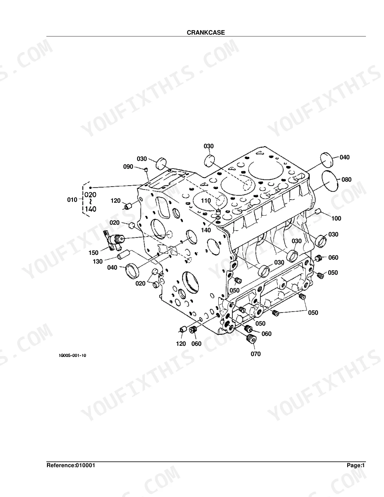
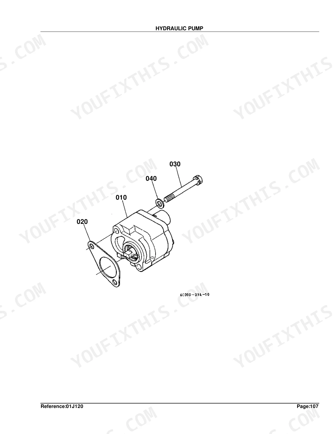
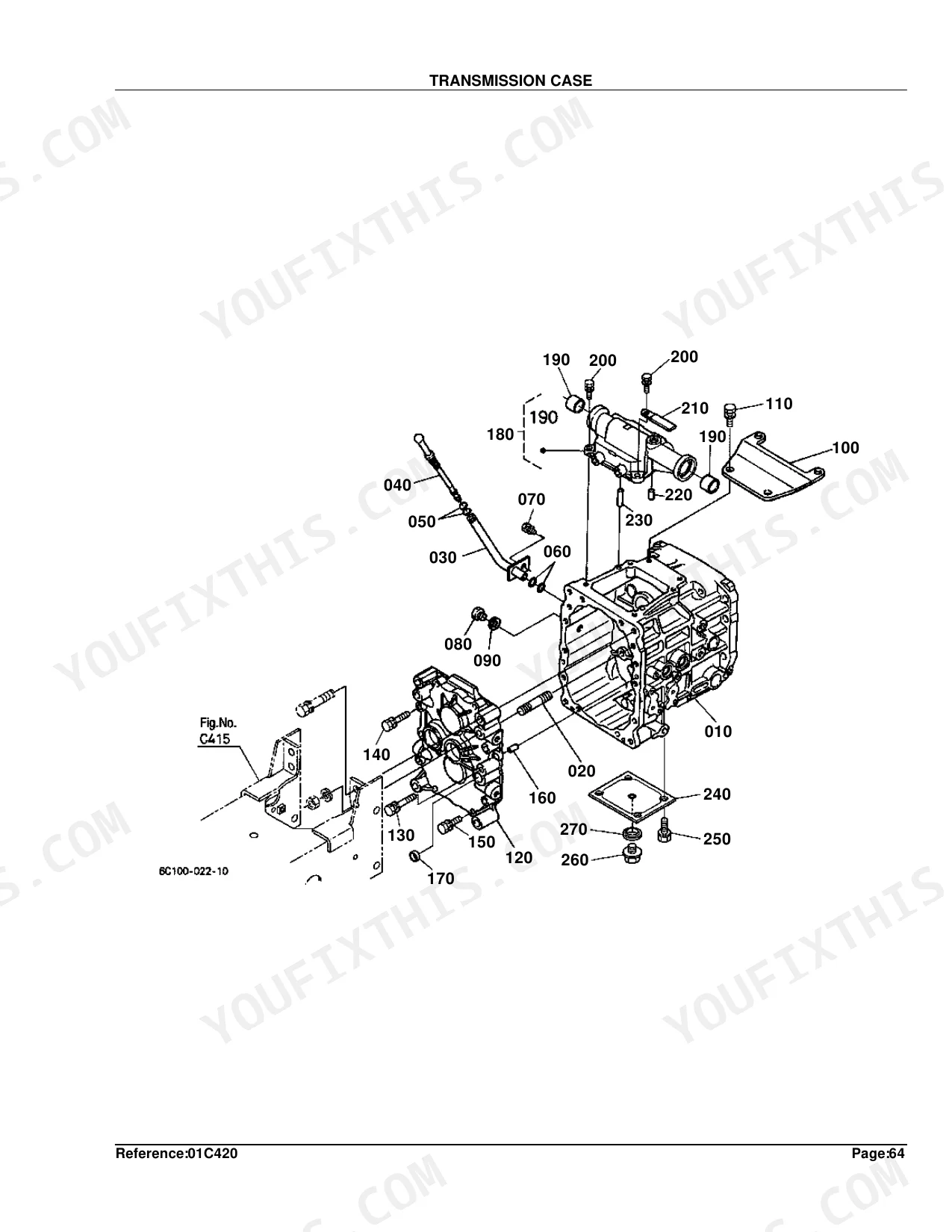
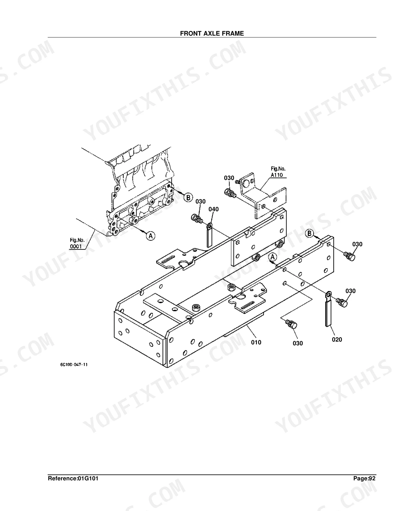
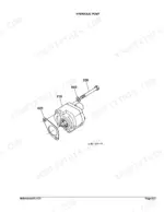
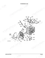
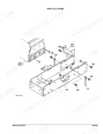
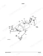
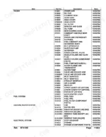
The B7410D parts catalog runs 338 pages, mapping one tractor from crankcase to ROPS with factory-correct part numbers. More than 150 of those pages are indexed parts lists covering every major system: injection pump, hydraulic cylinder, front axle, transmission shafts, and PTO. Each section pairs an exploded view with a numbered parts list and interchangeability data, and serial number split coverage at S.No. 4Z9999/5A0001 lets you match parts to your specific build. Part-level specs sit throughout the book: the battery replacement is model 55B24L, switch gasket thickness is 1.0mm, and the starter assembly weighs 3.7 kgf. Order the wrong part once and you remember how long that wait costs you. Everything is bookmarked by system and keyword-searchable, so you can find the exploded view, confirm the number, and order.
What's Inside This Kubota B7410D Parts Manual
| System | Pages |
|---|---|
| Crankcase | 7-8 |
| Oil Pan | 9-10 |
| Cylinder Head | 11-13 |
| Gear Case | 14-15 |
| Head Cover | 16-19 |
| Oil Filter | 20-21 |
| Dipstick and Guide | 22-23 |
| Oil Pump | 24-25 |
| Main Bearing Case | 26-27 |
| Camshaft and Idle Gear Shaft | 28-30 |
| Piston and Crankshaft | 31-32 |
| Flywheel | 33-34 |
| Fuel Camshaft and Governor Shaft | 35-36 |
| Idle Apparatus | 37-38 |
| Injection Pump | 39-40 |
| Governor | 41-42 |
| Speed Control Plate | 43-44 |
| Nozzle Holder and Glow Plug | 45-47 |
| Nozzle Holder [Component Parts] | 48-50 |
| Fuel Pump (Mechanical) | 51-52 |
| Water Flange and Thermostat | 53-54 |
| Water Pump | 55-56 |
| Valve and Rocker Arm | 57-60 |
| Inlet Manifold | 61-64 |
| Exhaust Manifold | 65-66 |
| Air Cleaner | 67-68 |
| Muffler | 69-70 |
| Upper Gasket Kit [Option] | 71-72 |
| Lower Gasket Kit [Option] | 73-74 |
| Piston Kit [Option] | 75-76 |
| Accelerator Lever | 77-78 |
| Fuel Tank | 79-80 |
| Fuel Pipe | 81-82 |
| Fuel Filter [Component Parts] | 83-84 |
| Fan | 85-86 |
| Water Pipe | 87-88 |
| Radiator [Except [AU] [NZ]] | 89-90 |
| Radiator [AU] [NZ] | 91-92 |
| Reserve Tank [Except [AU] [NZ]] | 93-94 |
| Reserve Tank [AU] [NZ] | 95-96 |
| Stop Solenoid | 97-98 |
| Dynamo | 99-100 |
| Dynamo [Component Parts] | 101-102 |
| Starter | 103-104 |
| Starter [Component Parts] | 105-106 |
| Battery | 107-108 |
| Switch | 109-110 |
| Panel Board | 111-112 |
| Panel Board [Component Parts] | 113-114 |
| Head Right | 115-116 |
| Hazard Light | 117-118 |
| Tail Light | 119-120 |
| Winker Lamp | 121-122 |
| Electrical Wiring | 123-124 |
| Clutch | 125-126 |
| Clutch Rod | 127-128 |
| Clutch Pedal | 129-130 |
| Clutch Housing | 131-132 |
| Clutch Dipstick and Guide | 133-134 |
| Center Frame | 135-136 |
| Transmission Case | 137-138 |
| Differential Gear Case | 139-140 |
| Rear Axle Case | 141-142 |
| Clutch Shaft | 143-144 |
| Propeller Shaft | 145-146 |
| Front Shaft | 147-148 |
| PTO Shaft | 149-150 |
| Rear Differential | 151-152 |
| Front Wheel Propeller Shaft | 153-154 |
| 2nd Shaft | 155-156 |
| 3rd Shaft | 157-158 |
| 4th Shaft | 159-160 |
| Main Gear Shift Fork | 161-162 |
| Range Gear Shift Fork | 163-164 |
| PTO Gear Shift Fork | 165-166 |
| Differential Lock Shift Fork | 167-168 |
| Rear Axle | 169-170 |
| Brake | 171-172 |
| Brake Rod | 173-174 |
| Parking Brake Lever [Except [AU] [NZ]] | 175-176 |
| Parking Brake Lever [AU] [NZ] | 177-178 |
| Main Gear Shift Lever | 179-180 |
| Range Gear Shift Lever | 181-182 |
| Front Wheel Drive Lever | 183-184 |
| PTO Gear Shift Lever | 185-186 |
| Hydraulic Control Lever | 187-188 |
| Brake Pedal | 189-190 |
| Differential Lock Pedal | 191-192 |
| Front Axle Frame | 193-194 |
| Front Axle Case | 195-204 |
| Front Differential | 197-198 |
| Differential Gear Shaft | 199-200 |
| Bevel Gear Case | 201-202 |
| Front Axle | 205-206 |
| Front Drive Shaft | 207-208 |
| Knuckle Arm | 209-210 |
| Drag Link | 211-212 |
| Tie Rod | 213-214 |
| Steering Handle | 215-216 |
| Steering Post | 217-218 |
| Steering Controller | 219-220 |
| Steering Controller [Component Parts] | 221-222 |
| Hydraulic Pump | 223-224 |
| Hydraulic Pump [Component Parts] | 225-226 |
| Hydraulic Oil Line (Suction) | 227-228 |
| Hydraulic Oil Line (Delivery) | 229-230 |
| Hydraulic Cylinder | 231-232 |
| Hydraulic Piston/Lift Arm | 233-234 |
| Feed Back Lever | 235-236 |
| Control Valve | 237-238 |
| Control Valve [Component Parts] | 239-240 |
| 3-Point Linkage 2 (Lift Rod) | 241-242 |
| Lower Link | 243-244 |
| 3-Point Linkage 1 (Top Link) | 245-246 |
| Check Chain | 247-248 |
| Drawbar | 249-250 |
| Rear Hitch | 251-252 |
| PTO Protector [Except [AU] [NZ]] | 253-254 |
| PTO Protector [AU] [NZ] | 255-256 |
| Front Grille [A] [CA] | 257-259 |
| Front Grille [AU] [NZ] | 260-261 |
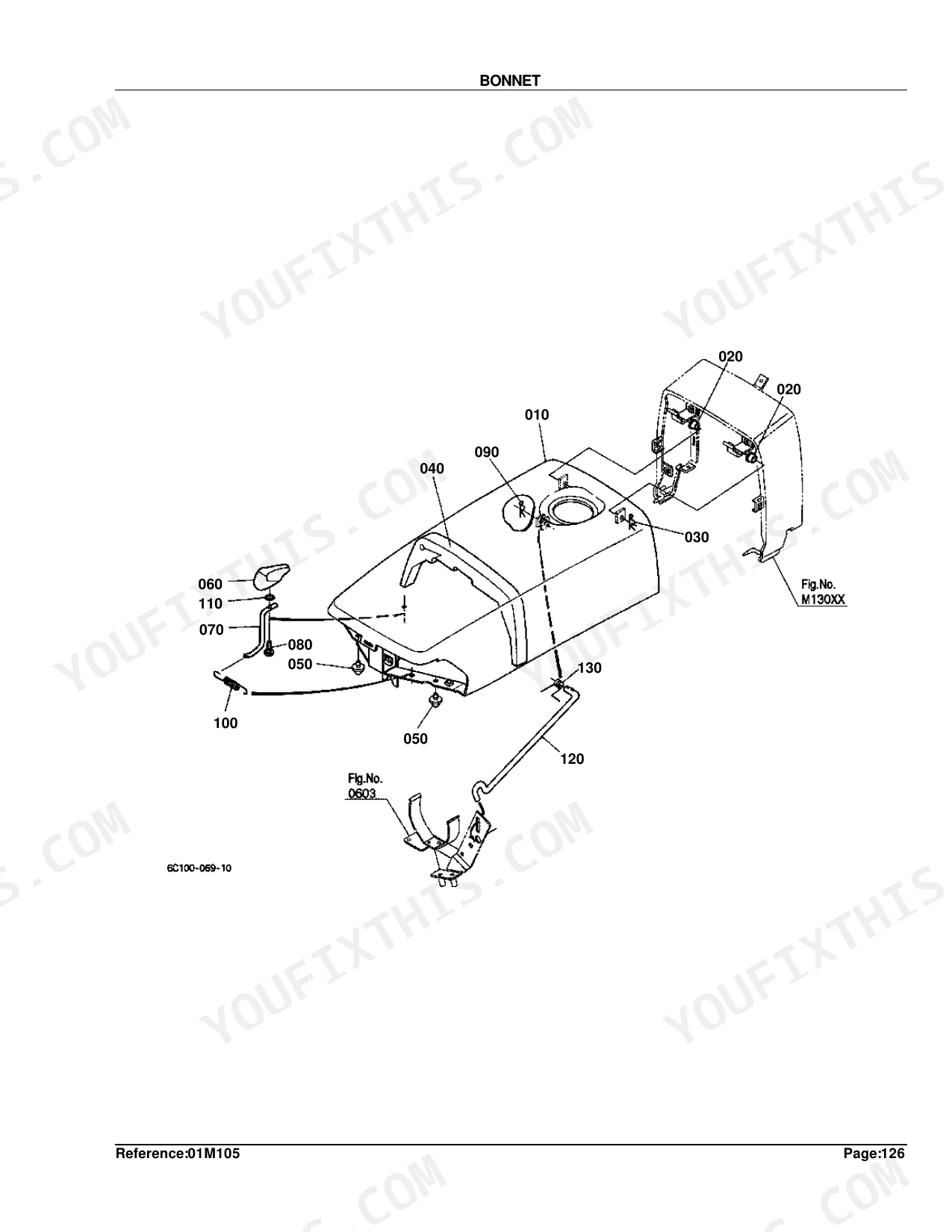
| Bonnet | 262-263 |
| Panel Cover | 264-265 |
| Side Cover | 266-267 |
| Shutter Plate [Except [AU] [NZ]] | 268-269 |
| Shutter Plate [AU] [NZ] | 270-271 |
| Lever Guide | 272-273 |
| Fender [Except [AU] [NZ]] | 274-275 |
| Fender [AU] [NZ] | 276-277 |
| Fender Stay | 278-279 |
| Floor Seat | 280-281 |
| Seat Support | 282-283 |
| Step | 284-285 |
| Rops (Rigid Type) [Except [AU]] | 286-287 |
| Rops (Foldable Type) [Except [AU]] | 288-289 |
| ROPS [AU] | 290-291 |
| Smv Emblem [Except [AU]] | 292-294 |
| Front Wheel (6-12) [Except [AU] [NZ]] | 295-296 |
| Front Wheel (23*8.50-12) [Except [AU] [NZ]] | 297-302 |
| Front Wheel (21*8.00-10) [Except [AU] [NZ]] | 299-300 |
| Front Wheel (6-12) [AU] [NZ] | 303-304 |
| Front Wheel (22*8.50-12) [AU] [NZ] | 305-306 |
| Rear Wheel (9.5-16) [Except [AU] [NZ]] | 307-309 |
| Rear Wheel (33*12.5-15) [Except [AU] [NZ]] | 310-312 |
| Rear Wheel (31*15.5-15) [Except [AU] [NZ]] | 313-315 |
| Rear Wheel (12-16.5) [Except [AU] [NZ]] | 316-318 |
| Rear Wheel (9.5-16) [AU] [NZ] | 319-321 |
| Rear Wheel (31*13.5-15) [AU] [NZ] | 322-324 |
| Label [Except [AU] [NZ]] [English] | 325-326 |
| Label [Except [AU] [NZ]] [French] | 327-328 |
| Label [AU] | 329-330 |
| Label [NZ] | 331-332 |
| Accessories and Service Parts | 333-334 |
| Working Light Kit [Option] | 335-336 |
| Working Light Kit [Option] | 337-338 |
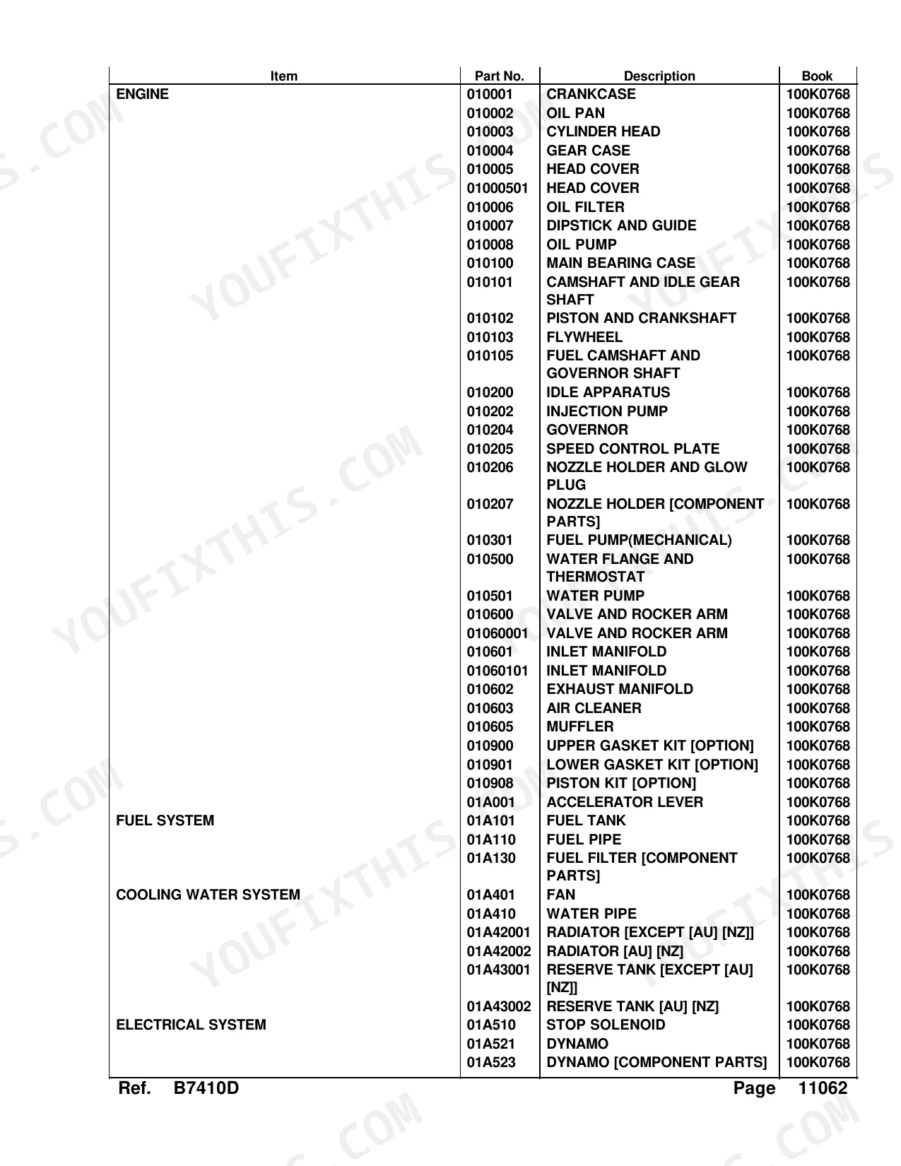
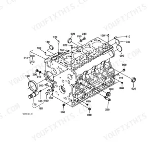
Every system also includes an exploded view diagram, interchangeability information, and a parts list table.
Quick Reference Specifications
| Specification | Value | Page |
|---|---|---|
| CARTRIDGE OIL FILTER weight | 0.195 kgf | p. 21 |
| ASSY STARTER weight | 3.7 kgf | p. 104 |
| ASSY BATTERY model | 55B24L | p. 108 |
| GASKET thickness | 1.0mm | p. 110 |
| KEY STARTER type | 2P/SET | p. 112 |
| ASSY BULB wattage | 1.7W | p. 114 |
| Gasket thickness (Switch) | 1.0mm | p. 110 |
| Fuse rating (Switch) | 30A | p. 110 |
| Bulb power (Panel Board) | 1.7W | p. 114 |
| Gear teeth count (Clutch Shaft) | 15T | p. 144 |
| Shim thickness (PTO Shaft) | 1.4mm | p. 150 |
| Pinion Differential teeth count (Rear Differential) | 12T | p. 152 |
Kubota B7410D Common Problems This Manual Covers
Kubota B7410D no-start condition, trying to identify correct starter assembly and battery replacement parts p. 103
Open the Starter diagram on page 103 and the Starter Component Parts list on page 105 to identify all sub-assemblies by item number. The complete starter assembly weighs 3.7 kgf (page 104), which helps confirm the correct unit. For the battery, turn to page 107: the specified replacement is model 55B24L, confirmed on page 108.
Manual Section: StarterCan't identify correct switch gasket thickness or fuse rating for electrical panel rebuild p. 109
Expand the Switch exploded view on page 109. Multiple gasket thicknesses appear in the parts list; the primary gasket is 1.0mm, confirmed on page 110. The fuse shown is rated 30A. Cross-reference Panel Board Component Parts on page 113 and the Electrical Wiring diagram on page 123 to capture any additional switch circuit parts before ordering.
Manual Section: SwitchHitch lifts slowly or sticks, can't match correct control valve and hydraulic cylinder parts p. 237
Start with the Control Valve exploded view on page 237. The Component Parts list on page 239 breaks out every seal, spool, and shim; the control valve shim thickness is 0.4mm (page 240). Also pull the Hydraulic Cylinder diagram on page 231 and the Feed Back Lever parts on page 235 to capture all hitch circuit components before ordering.
Manual Section: Control ValveRoutine service due, can't confirm correct oil filter and fuel filter part numbers p. 20
Bring up the Oil Filter diagram on page 20. The cartridge oil filter assembly weighs 0.195 kgf (page 21), useful for confirming the correct part is in hand. For fuel filtration, turn to Fuel Filter Component Parts on page 83. Cross-reference the Oil Pan diagram on page 9 and Fuel Tank parts on page 79 to complete the full service kit list.
Manual Section: Oil FilterHST pedal worn or sloppy, need part numbers for transmission shift fork components p. 137
Pull the Transmission Case diagram on page 137 for overall layout. Turn to Main Gear Shift Fork on page 161 and Range Gear Shift Fork on page 163 to identify worn shift components. The PTO Shaft section on page 149 covers shim specs; correct shim thickness is 1.4mm (page 150). Check the Clutch Shaft diagram on page 143 to match any gear components.
Manual Section: Transmission CaseFrequently Asked Questions
What are the replacement specifications for engine oil filter?
Use Part No. 15853-32430, listed as a CARTRIDGE OIL FILTER. Quantity is 1, and it weighs 0.195 kgf (0.429 lb).
What format is this Kubota B7410D manual in?
Immediate download of the complete 338-page searchable Parts Catalog. Open it on any device: laptop at your desk or phone out in the field.
Are there any print restrictions on this Kubota B7410D manual?
Yes. The PDF carries no DRM restrictions, so you can print any page or section you need for your shop. Works with any standard printer.
Does this Kubota B7410D Parts Catalog cover the hydraulic system?
This is a parts catalog, so it shows exploded parts diagrams rather than circuit schematics. It includes detailed exploded views of the hydraulic components — pump, control valve, cylinder, and oil lines — with OEM part numbers, not wiring-style circuit diagrams.
Document Quality
This document is a high-quality scanned PDF with an accurate OCR layer, enabling you to search and copy text from all pages. The text is consistently crisp and easy to read, appearing sharp even in scanned sections. All diagrams and illustrations are clear raster images, with lines, labels, and numbers remaining easily readable at various zoom levels. The pages are clean, free of scan artifacts or marks, and there are no notable blank or filler pages present.


Reviews
There are no reviews yet.