
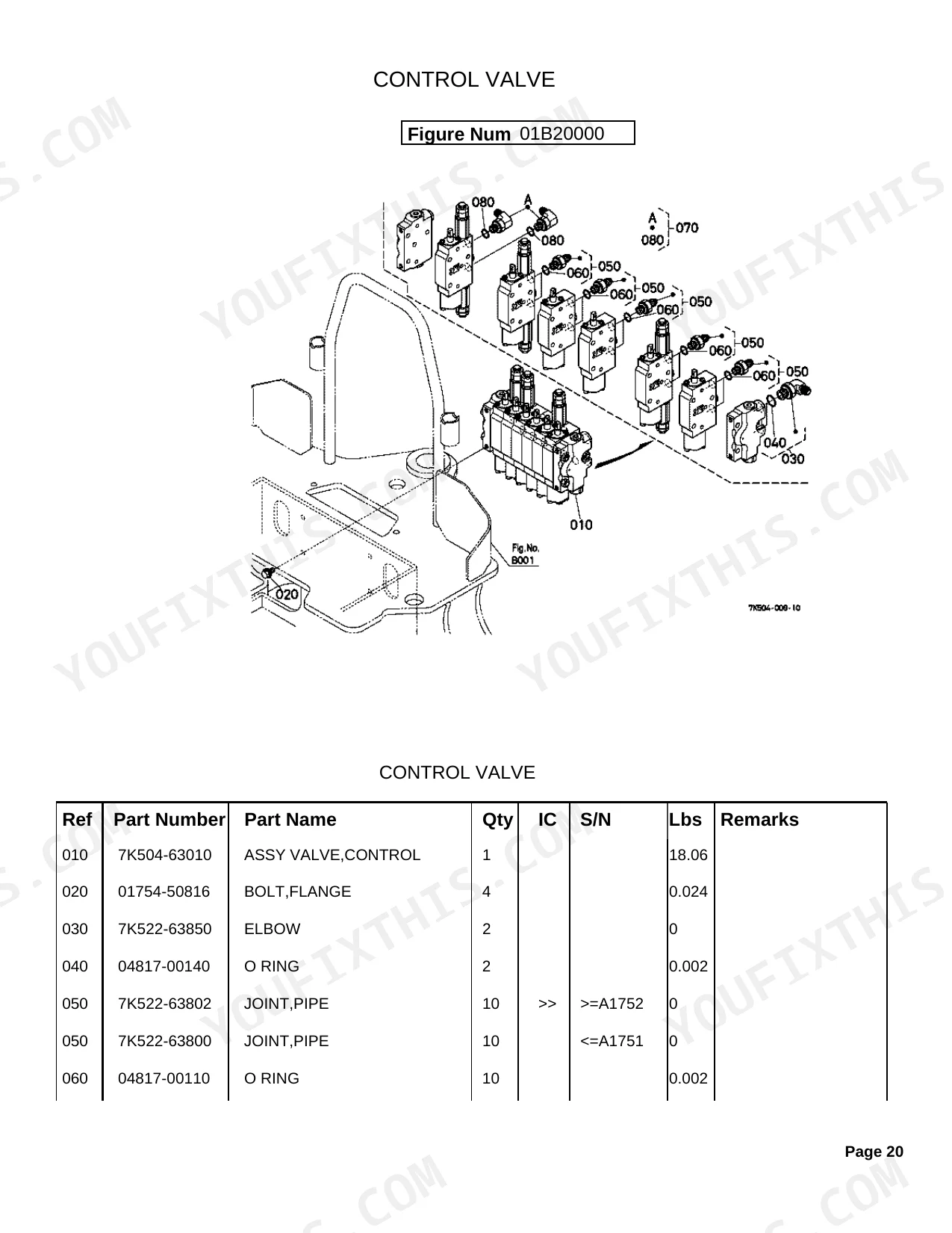
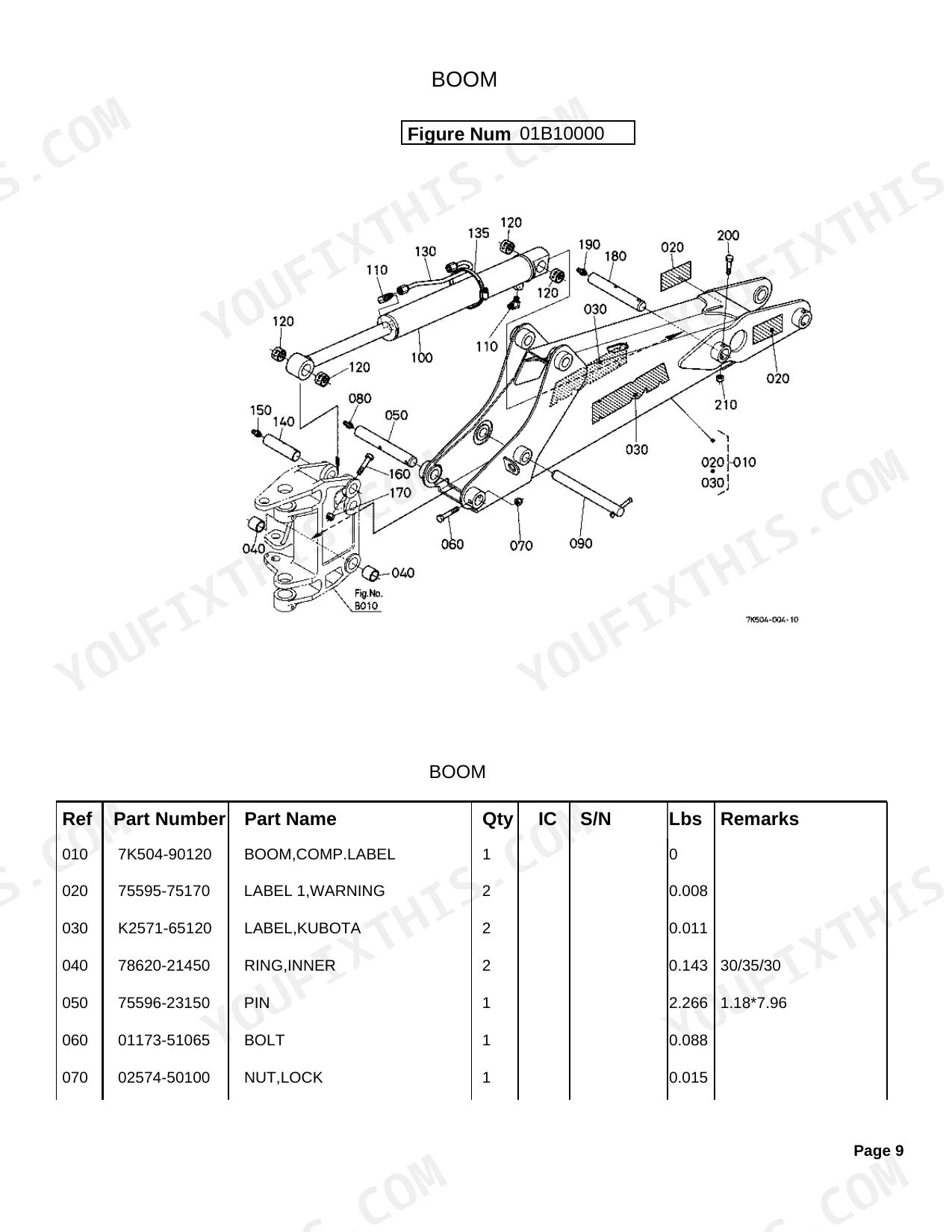
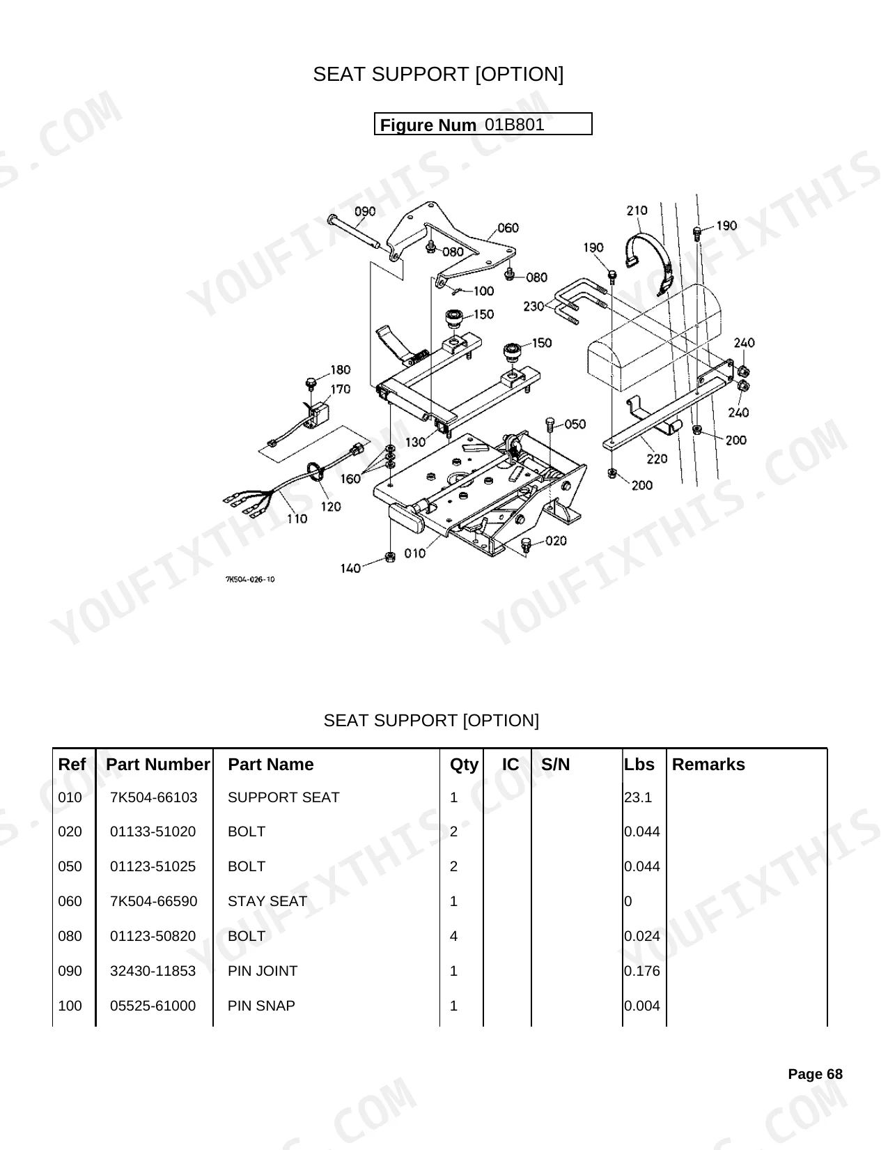
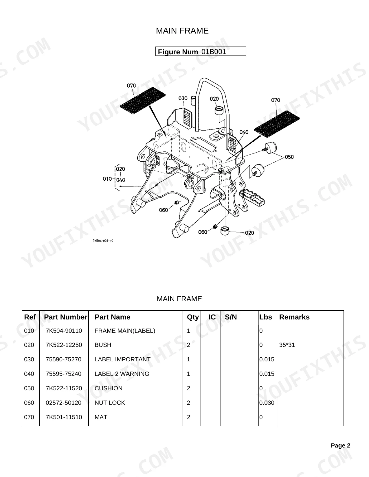
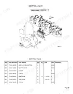
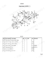
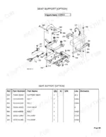
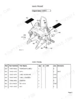
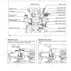
Factory OEM parts data for the Kubota BH65 Backhoe Attachment fills all 76 pages here, with exploded views and part numbers across every major assembly. Coverage runs from the Main Frame and Swing Frame through the Front Attachments (Swing Cylinder, Boom, Dipperstick, Bucket, Stabilizer Arm), then into the Control Valve with spool breakdowns for Swing, Boom, Stabilizer, Dipperstick, and Bucket, plus component parts for all five Hydraulic Cylinders. Hose routing is mapped circuit by circuit: Intake, Swing, Boom/Dipper, Bucket, and Stabilizer. Specs come straight from the factory; the Swing Frame grease fitting runs 1/8-27NPT thread, and the Boom Pin measures 1.18*7.96 inches. Optional sections cover the Mount Kit, Seat Support, and Thumb Arm Kit, each with part numbers. With your machine down and the dealer a week out, download it, search by keyword or jump between bookmarked sections, and order the right part today.
What's Inside This Kubota BH65 Parts Manual
| System | Pages |
|---|---|
| Main Frame | 3-4 |
| Swing Frame | 5-6 |
| Front Attachments | 7-19 |
| Control Valve | 20-34 |
| Hydraulic System | 35-42 |
| Hydraulic Cylinder | 43-53 |
| Operator'S Platform | 54-56 |
| Control Lever | 57-61 |
| Labels | 62-64 |
| Option | 65-76 |
Quick Reference Specifications
| Specification | Value | Page |
|---|---|---|
| BUSH dimension | 35*31 mm | p. 3 |
| FITTING GREASE thread | 1/8-27NPT | p. 5 |
| PIN dimension | 25*107 mm | p. 8 |
| BOOM RING,INNER dimension | 30/35/30 mm | p. 10 |
| BOOM PIN dimension | 1.18*7.96 inches | p. 10 |
| DIPPERSTICK PIN dimension | 25*137 mm | p. 13 |
| BUCKET TOOTH BOLT ON weight | 3.19 lbs | p. 16 |
| STABILIZER ARM PIN dimension | 25.4*105 mm | p. 18 |
| CONTROL VALVE ASSY weight | 18.06 lbs | p. 21 |
| CYLINDER(SWING) HEAD dimension | 60*30 mm | p. 44 |
| NIPPLE GREASE thread | M8*1.25 | p. 45 |
Kubota BH65 Common Problems This Manual Covers
Kubota BH65 hydraulic hose part number needed, old hose has no visible identification markings p. 35
Find the Hydraulic System exploded views starting on page 35. Each hose assembly is broken out by circuit: Intake, Swing, Boom/Dipper, Bucket, and Stabilizer. Locate your specific hose in the matching circuit diagram, note the part number, then cross-reference the parts list to confirm the correct fitting size and thread spec for your serial number range.
Manual Section: Hydraulic SystemMounting pins won't seat during attachment, need correct replacement pin dimensions and part number p. 7
Check the Front Attachments parts diagram starting on page 7. The standard swing cylinder connection pin measures 25*107 mm (page 8); verify that dimension matches what you're replacing before ordering. If it's the stabilizer arm pin, that one is 25.4*105 mm (page 18). Order by part number from the corresponding parts list.
Manual Section: Front AttachmentsBoom cylinder leaking, seal kit part number unclear on the exploded view diagram p. 43
Open the Hydraulic Cylinder section at page 43. Each cylinder (Swing, Boom, Dipper, Bucket, and Stabilizer) has its own component parts diagram listing every seal, O-ring, and wiper by part number. The swing cylinder head is 60*30 mm (page 44); match your cylinder before pulling seals to avoid ordering the wrong kit.
Manual Section: Hydraulic CylinderControl valve disassembled, cannot identify individual spool component part numbers for replacement order p. 21
Start in the Control Valve section at page 20. Each spool section, Swing, Boom, and Stabilizer, has its own component parts diagram on page 21. Find your specific spool by function, then pull the part number for each internal component. The complete valve assembly weighs 18.06 lbs; confirm the section before ordering individual spool parts.
Manual Section: Control ValveGrease fitting stripped on swing frame, need correct thread spec to source replacement fitting p. 5
Locate the correct fitting spec before ordering. Swing Frame grease fittings (page 5) use 1/8-27NPT thread; boom and dipperstick fittings (page 11) use 1/4-28T.T.*.68. Match the part number from the corresponding exploded view, not just the thread size. Kubota uses different fitting styles in adjacent locations on the same machine.
Manual Section: Swing FrameBucket tooth worn completely flat, need to identify correct bolt-on tooth part number p. 16
Pull up the Front Attachments section at page 7 for the bucket assembly diagram. Bolt-on tooth assemblies are listed with individual part numbers; each bolt-on tooth weighs 3.19 lbs (page 16), so confirm count before placing your order. Cross-reference the parts list to verify adapter compatibility if you're switching tooth profiles.
Manual Section: Front AttachmentsFrequently Asked Questions
What are the replacement specifications for hydraulic couplers?
A hydraulic coupler is listed under part number 7J612-66320, carrying a specification of 1/4(72C4-4F).
What format is this Kubota BH65 manual in?
This is a 76-page searchable PDF ready for immediate download. It works on any device, so you can pull it up on your phone while you're under the hood. No shipping, no waiting.
Can I print specific sections of this Kubota BH65 Parts Catalog?
Absolutely. No DRM or copy protection. Print the whole manual or just the pages you need. Any home or office printer works.
Are hydraulic system diagrams in this Kubota BH65 Parts Catalog?
Yes. Exploded views of hydraulic components, hose routing, and cylinder breakdowns are included, showing part numbers for all hydraulic system elements.
Document Quality
This document is a scanned PDF with an optical character recognition (OCR) layer, allowing you to search and copy the full text. All text is crisp and easy to read, with no blurriness or fading present. Diagrams and illustrations are clear black and white line drawings, which appear to be raster images at a good resolution, and all labels within them are readable. The pages are clean, free of scan artifacts, stains, or skewed content. You will find a few blank filler pages that only contain a page number.


Reviews
There are no reviews yet.