
This Kubota BH77 Assembly Instructions manual (OEM #7K503-7916-2) does one job: getting your backhoe off the crate and bolted to the tractor correctly. Of its 70 pages, 50 are exploded-view diagrams covering every sub frame, hydraulic line route, and boom component, followed by assembly sequences for six tractor configurations: BH4972, BH4975, BH4984, BH4962, BH4996, and BH4986. Each variant gets its own line routing, seat and control lever setup, dipperstick and bucket assembly, and a post-assembly inspection checklist. Sub frame M16 mounting bolts torque to 196 to 225 N-m; the 3/4-inch UNF flare nut fittings snug down to 36 to 40 N-m. Miss one bolt on the sub frame and you're booking a service call after delivery. Section bookmarks let you jump to your variant, open the right diagram, and mount the backhoe.
What's Inside This Kubota BH77 Manual
| System | Pages | Key Topics |
|---|---|---|
| To The Dealer | 4-5 | This Manual Contains Procedures Intended To Assist The Dealer In Unpacking And Assembling The Product Before Delivering To The Customer |
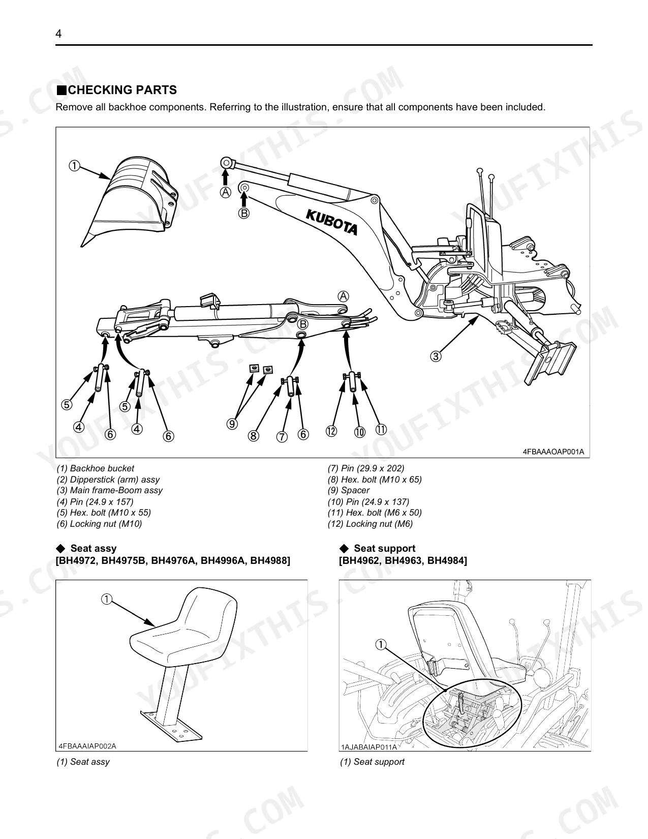
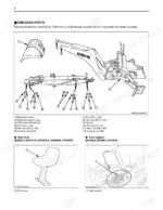
| Unpacking and Checking Parts | 6-9 | Unpacking Wooden Crate, Checking Parts (Seat: Assy, Support), Bh4984, Bh4988, Bh4975B, Bh4996A, Bh4976A, Bh4986 |
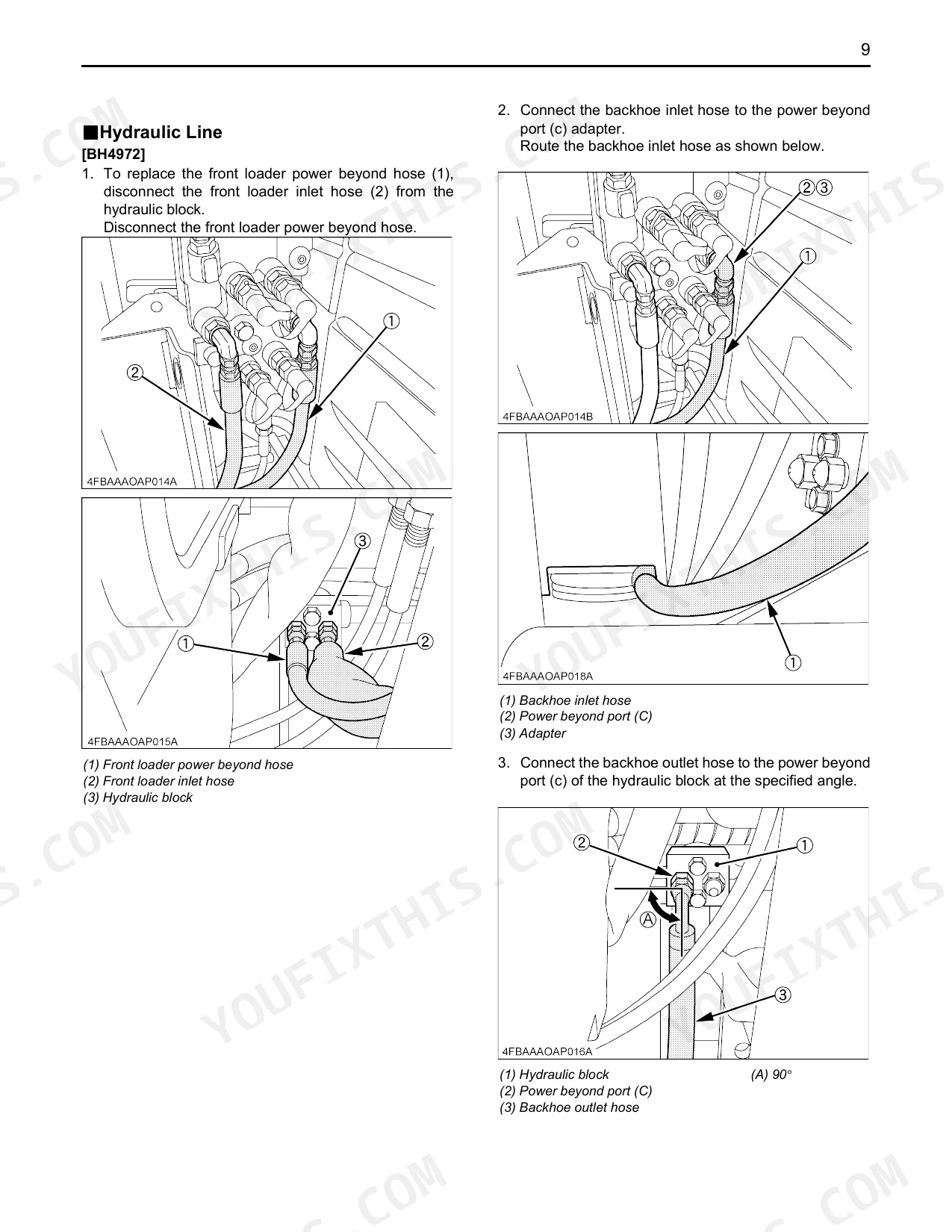
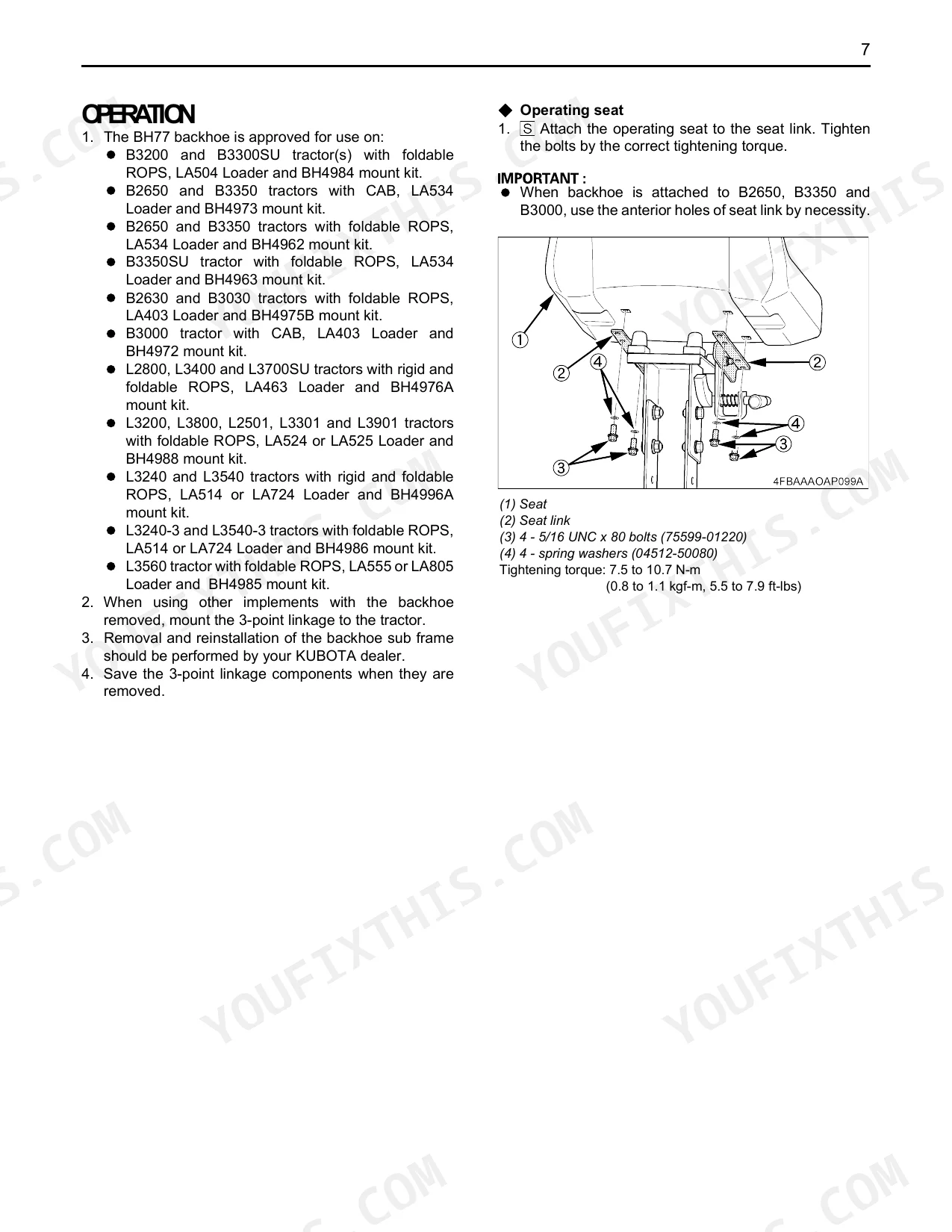
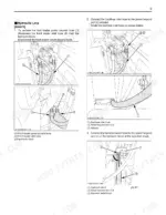
| Operation | 10-55 | Operating Seat, Operating Seat Support Link, Assembly [BH4972 BH4975 BH4976 BH4988] (Layout Of BH77 Backhoe Hydraulic Lines), Tractor Preparation, Hydraulic Line, Sub Frame |
| Setting Up The Backhoe | 56-58 | Dipperstick, Seat [Except BH4962 BH4963 BH4984], Step Plate [BH4962 BH4963 BH4984], Control Lever [BH4962 BH4963 BH4984], Bucket |
| Installing The Backhoe | 59-60 | Mech. Thumb BH1976 (Thumb Weldment, Pin, Adjust Link 1, Adjust Link 2, Set Adjust Pin), Remove The 3-Point Hitch And / Or Drawbar, Make Sure The Swing Lock Pin Is Installed |
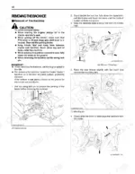
| Removing The Backhoe | 61-63 | Removal Of The Backhoe, Set The Swing Lock Pin To Prevent The Pivoting Of The Boom Before Removing The Backhoe, Stand Beside The Rear Tire, Fully Close The Dipperstick |
| Pre-Operation Check | 64-66 | Storage Of The Backhoe, Lubrication, Transmission Fluid |
| Assembly Time | 67 | Assembly By One Worker, Following Tools And Equipment Are Available |
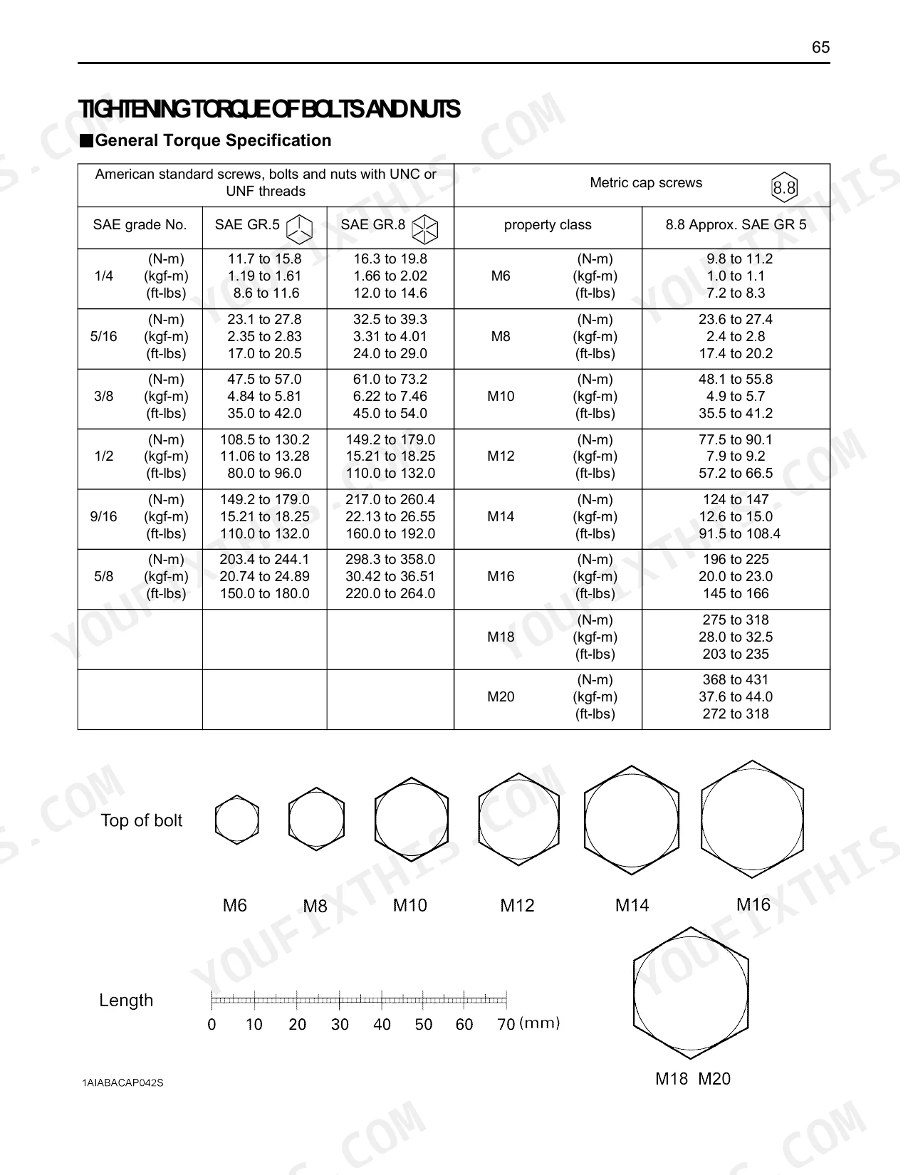
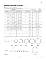
| Tightening Torque of Bolts and Nuts | 68 | General Torque Specification |
| Tightening Torque of Adaptors, Elbows and Others | 69 | - |
| Check List for Inspection After Assembly | 70 | - |
Quick Reference Specifications
| Specification | Value | Page |
|---|---|---|
| Sub frame M16 bolts tightening torque (BH4972, BH4975, BH4962, BH4963, BH4973, BH4996, BH4986) | 196 to 225 N-m | p. 18 |
| Hose fitting, Flare nut (UNF) 3/4 thread size tightening torque | 36 to 40 N-m | p. 69 |
| Backhoe inlet pipe / Female coupler tightening torque (BH4962, BH4963, BH4973) | 39 to 60 N-m | p. 28 |
| Control lever M6 x 16 bolts tightening torque (BH4962, BH4963, BH4984) | 9.8 to 11.2 N-m | p. 58 |
| General torque specification for M10 bolts (8.8 property class) | 48.1 to 55.8 N-m | p. 68 |
| Locking nut clearance (gap between boss and locking nut) for dipperstick assembly | 1 to 3 mm | p. 56 |
| Grease type for all grease fittings | SAE multipurpose grease | p. 64 |
| Mech. Thumb grease fitting thread size | 1/4 - 28T.T. X.68 | p. 59 |
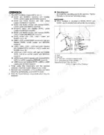
| Operating Seat Tightening Torque | 7.5 to 10.7 N-m | p. 10 |
| Cab Spacer (BH4972) Tightening Torque | 368 to 431 N-m | p. 20 |
| Rear Wheels (BH4976, BH4988) Tightening Torque | 215 N-m | p. 21 |
| Backhoe Inlet/Outlet Pipe (BH77 kit) Tightening Torque | 39 to 60 N-m | p. 28 |
Kubota BH77 Common Problems This Manual Covers
Boom or dipperstick has weak digging force, stalls, or won't lift under load p. 59
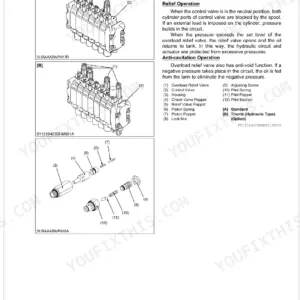
Inspect the relief valve in the main hydraulic valve circuit first. Cycle each function individually and note which cylinder loses force; a single weak function points to a cylinder-specific relief valve, not the main pump. Torque all hydraulic inlet and outlet pipe fittings to 39 to 60 N-m (page 28). After reseating or replacing the relief valve, check hydraulic oil level and cycle all functions per the Backhoe Hydraulic System Check on page 59.
Manual Section: Backhoe Hydraulic System CheckOne cylinder stops working: dipperstick won't extend while bucket, boom, and swing still operate p. 64
Trace the hydraulic circuit for that one cylinder. A stuck spool or failed relief valve isolates a single function while the rest operate normally. Make sure every hose connection is fully seated and torqued; flare nut UNF 3/4 fittings torque to 36 to 40 N-m (page 69). Look for kinks or restrictions in the lines feeding that cylinder, then consult Backhoe Component Repair/Replacement on page 64 for worn or damaged valve components.
Manual Section: Backhoe Component Repair/ReplacementSwing won't move in one direction after hose replacement or hydraulic work p. 59
Verify the swing circuit relief valve first; it's the usual culprit once hydraulic work has disturbed the circuit. Confirm the swing lock pin is out before testing. Re-check every hose connection in the swing circuit, tightening adjustable elbow UNF 9/16 fittings to 37 to 44 N-m (page 69). Cycle swing left and right under light load; if one direction still fails, pull the relief valve and inspect it for debris or seat damage.
Manual Section: Backhoe Hydraulic System CheckControl sticks feel sloppy, vague, or have excessive play when operating p. 56
Work through the linkage from the lever down to the cylinder connections. Test every bolt and nut for tightness; M10 linkage hardware torques to 48.1 to 55.8 N-m (page 68). Apply threadlocker to any fastener that has backed out. Set the dipperstick locking nut so the gap between the boss and nut measures 1 to 3 mm (page 56). Lubricate all pivot points and grease fittings with SAE multipurpose grease per the Pre-Operation Check on page 64.
Manual Section: Setting Up The BackhoeControl levers bind, scrape, or feel stiff moving forward and backward p. 64
Look at the guide plate position first; misalignment pinches the rod and drags even when the linkage is otherwise intact. Loosen the guide plate, center the control rod by feel, then reposition and tighten. Torque the control lever M6 x 16 bolts to 9.8 to 11.2 N-m. Pack the guide plate contact area with SAE multipurpose grease (page 64), then work the lever through full travel several times to confirm smooth movement with no scraping.
Manual Section: Pre-Operation CheckBackhoe hard to align during installation, receiver pins won't drop correctly p. 59
Confirm the 3-point hitch and drawbar are removed before attempting hookup — the manual covers this in the Installing The Backhoe section starting on page 59. Lower the tractor's hydraulic hitch slowly and use a spotter to align the sub frame receiver pins. Once seated, torque sub frame M16 bolts to 196 to 225 N-m (page 18). Run through the Post-Assembly Inspection Checklist on page 70 before first operation.
Manual Section: Installing The BackhoeFrequently Asked Questions
What are the replacement specifications for Hydraulic hoses?
Hose connections and sizes are spelled out in the manual. The backhoe inlet and outlet hoses use a 3/4 - 16 UNF thread, torqued to 36 to 40 N-m (3.7 to 4.1 kgf-m, 27 to 30 ft-lbs). Dipperstick hoses are identified as 9/16-18.
What format is this Kubota BH77 manual in?
It's a 70-page searchable PDF, ready to download right away. Opens on any device, so you can pull it up on your phone while you're under the hood. No shipping, no waiting.
Am I able to print pages from this Kubota BH77 manual?
Yes. The PDF carries no DRM restrictions, so print any page or section you need for your shop. Any standard printer handles it.
Document Quality
This document is a scanned PDF, not a native digital file. An OCR layer is present, so you can search and copy text throughout the manual. The text is consistently readable, though it has the slight fuzziness typical of scanned documents rather than vector sharpness. All diagrams and illustrations are raster images, which are clear enough for labels to be read but will pixelate if zoomed in significantly. The pages are generally clean with minor scan artifacts, and there are no notable blank or filler pages.

Reviews
There are no reviews yet.