
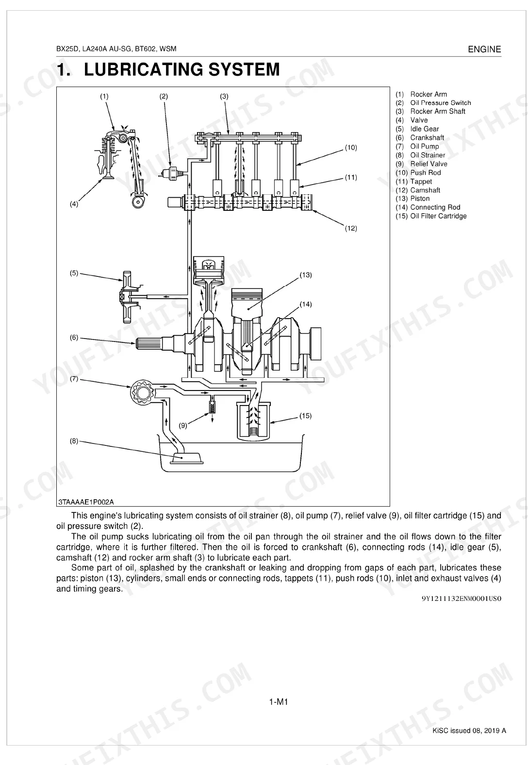
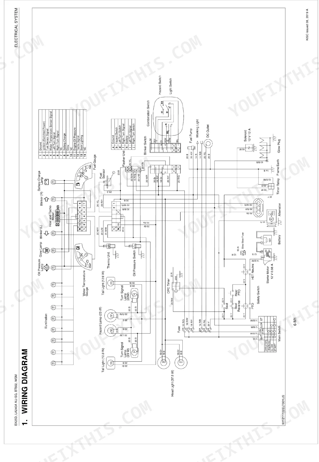
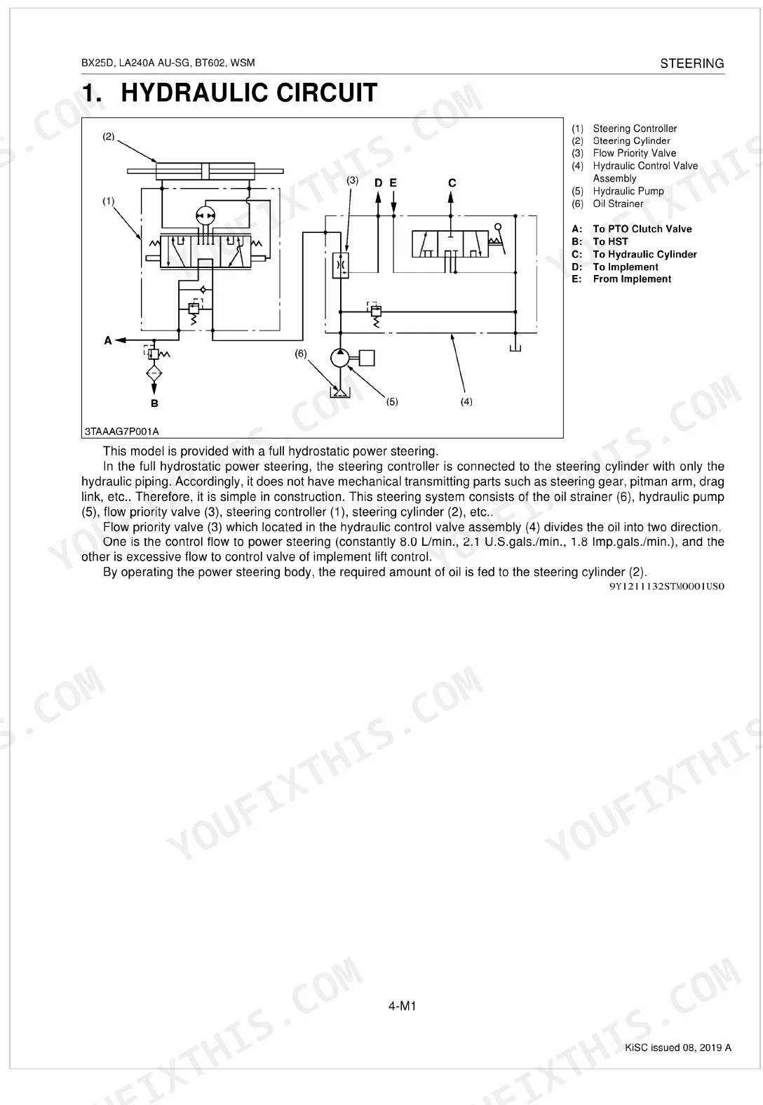
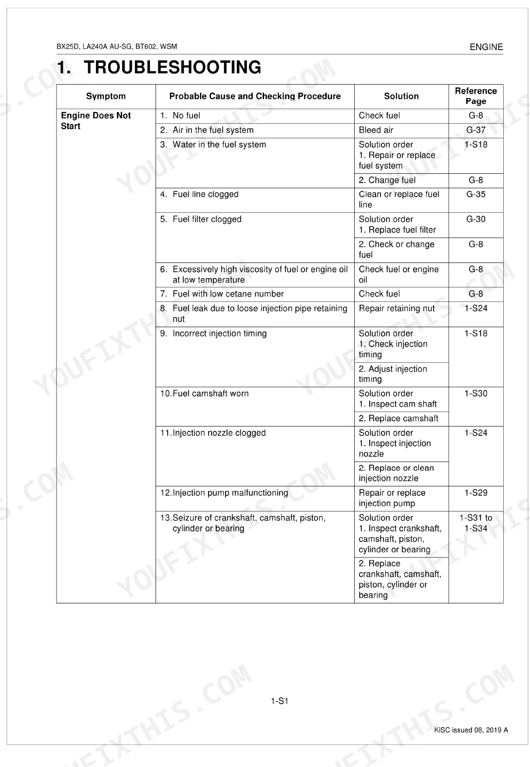
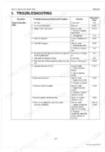
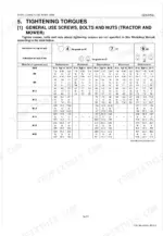
This Kubota BX25DLB-AU, LA240A AU-SG, BT602 Shop Manual (OEM #9Y111-11322) delivers factory-accurate service for your 2014-2019 tractor, front loader, and backhoe combo across 411 pages. Hydraulic circuit schematics map the full loader and backhoe control valve assemblies, while a dedicated wiring section details safety switch logic and OPC circuits. Troubleshooting spans 26 pages covering engine, transaxle, steering, hydraulic, electrical, front loader, and backhoe systems. Tightening torques are broken out per subsystem: the BT602 boom cylinder head runs 350-400 N-m, the swing cylinder head 300-350 N-m, and the dipperstick and stabilizer cylinder heads 250-280 N-m. Three attached systems share one machine, so a $40 forum guess can sideline all of them for a week. Section bookmarks and keyword search drop you on the exact spec, whether you're at the office laptop or the tablet beside the machine.
What's Inside This Kubota BX25DLB-AU, LA240A AU-SG, BT602 Manual
| System | Pages | Key Topics |
|---|---|---|
| Record of Revisions | 3 | - |
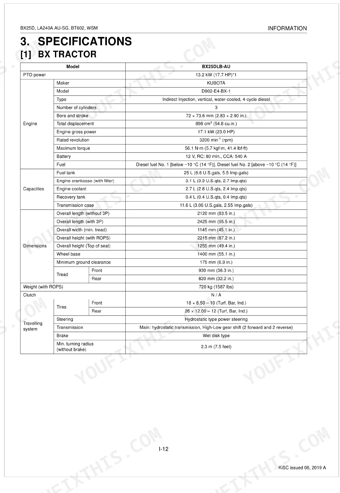
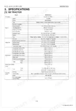
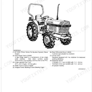
| Information | 4-25 | Safety First, Safety Decals (Bx25Dlb-Au, La240A Au-Sg, Bt602, Attachments), Specifications (Bx Tractor, Bt602), Traveling Speeds, Dimensions |
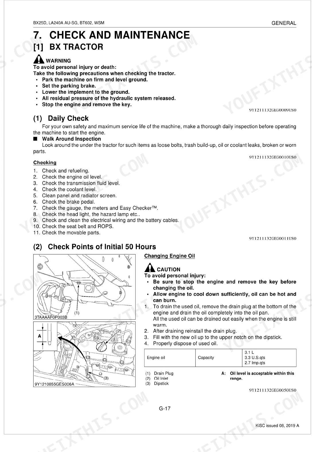
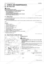
| General | 26-86 | Identification, Handling Precautions For Electrical Parts And Wiring, Lubricants, Fuel And Coolant (Bx Tractor, Front Loader, Backhoe) |
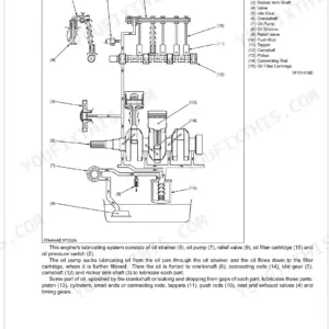
| Engine | 87-91 | Lubricating System, Cooling System, Fuel System |
| Engine Servicing | 92-142 | Engine Body, Lubricating System, Cooling System, Fuel System, Cylinder Head, Valves |
| Transaxle | 143-163 | Structure, Traveling System (Hydrostatic Transmission, Range Gear Shift Section, Front Wheel Drive Section, Differential Gear Section, Brake Section) |
| Transaxle Servicing | 164-210 | Hydrostatic Transmission, Hydraulic Cylinder, Transaxle, PTO Clutch, Differential, Brake |
| Front Axle | 211-214 | Structure, Camber, Kingpin Angle, Caster, Toe-in |
| Front Axle Servicing | 215-229 | Power Steering Cylinder, Bevel Gear Case, Front Gear Case, Differential Gear |
| Steering | 230-234 | Hydraulic Circuit, Steering Controller, Steering Cylinder |
| Steering Servicing | 235-245 | Relief Valve, Steering Controller, Power Steering Cylinder, Tie-rod, Meter Panel |
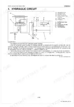
| Hydraulic System | 246-268 | Hydraulic Circuit, Hydraulic Pump, Control Valve, Flow Priority Valve, Relief Valve, Hydraulic Cylinder, Hydraulic Block Type Outlet, Mower Linkage |
| Hydraulic System Servicing | 269-287 | Relief Valve, Hydraulic Pump, Mower Lift Linkage, Hydraulic Cylinder, Control Valve |
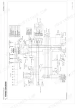
| Electrical System | 288-301 | Wiring Diagram, Starting System (Main Switch Position, Safety Switch, Operator Presence Control), Charging System (Electrical Circuit, Ic Regulator), Lighting System |
| Electrical System Servicing | 302-339 | Battery, Main Switch, Starter, Glow Plug, Safety Switch, Fuel Pump, Alternator |
| Front Loader | 340-355 | Hydraulic Circuit Schematic, Control Valve Assembly, Boom Cylinder And Bucket Cylinder, Relief Valve |
| Front Loader Servicing | 356-370 | Spill Guard, Bucket, Boom, Hydraulic Cylinders, Side Frames, Main Frames |
| Backhoe | 371-390 | Hydraulic Circuit, Control Valve (Structure, Operation, Overload Relief Valve), Hydraulic Cylinder |
| Backhoe Servicing | 391-411 | Control Valve, Boom, Dipperstick, Bucket, Swing Cylinder, Stabilizer Cylinder |
Quick Reference Specifications
| Specification | Value | Page |
|---|---|---|
| Boom cylinder head torque | 350 to 400 N-m | p. 396 |
| Dipperstick cylinder, stabilizer cylinder head torque | 250 to 280 N-m | p. 396 |
| Battery Voltage (Factory Specification) | More than 12 V | p. 309 |
| Battery Potential Difference (Allowable Limit) | Less than 0.1 V | p. 309 |
| Battery Terminal Connection Potential difference (Allowable Limit) | Less than 0.1 V | p. 312 |
| Starter Commutator O.D. (Factory Specification) | 30.0 mm | p. 309 |
| Starter Commutator O.D. (Allowable Limit) | 29.0 mm | p. 309 |
Kubota BX25DLB-AU, LA240A AU-SG, BT602 Common Problems This Manual Covers
Engine cranks slowly in cold weather, or the starting system clicks without turning the engine over. p. 309
Check battery voltage; it should read more than 12 V per page 309. Scrub corroded terminals, then confirm the connection potential difference stays under 0.1 V (page 312). Charge the battery until specific gravity hits 1.260 Sp. Gr. before retesting.
Manual Section: Electrical System ServicingBackhoe boom cylinder weeps hydraulic oil around the head seal, or it won't lift heavy loads. p. 396
Inspect the cylinder rod for deep scratches and swap out the damaged packing seals. Reassemble, then torque the boom cylinder head to 350 to 400 N-m as specified on page 396. Work the control valve through its full stroke to bleed trapped air from the lines.
Manual Section: Backhoe ServicingElectrical accessories die completely, or the starter won't engage when you turn the ignition switch. p. 313
Test the main fuse block and check the wiring harness for moisture intrusion. Measure battery specific gravity to confirm it reads 1.260 Sp. Gr. as shown on page 313. Clean the main ground cable if voltage drop runs past the allowable limit during cranking.
Manual Section: Electrical System TroubleshootingFrequently Asked Questions
How do I reset the Kubota BX25D reverse pedal adjustment?
Depress the speed control pedal to the "Reverse" position, then release your foot. Adjust the locking screw (5) until the rear axle stops rotating. Set the reverse stopper bolt (B) to a length of 17.5 mm (0.689 in.) and lock it securely.
What is the torque spec for Kubota BX25DLB-AU / BT602 mounting bolts?
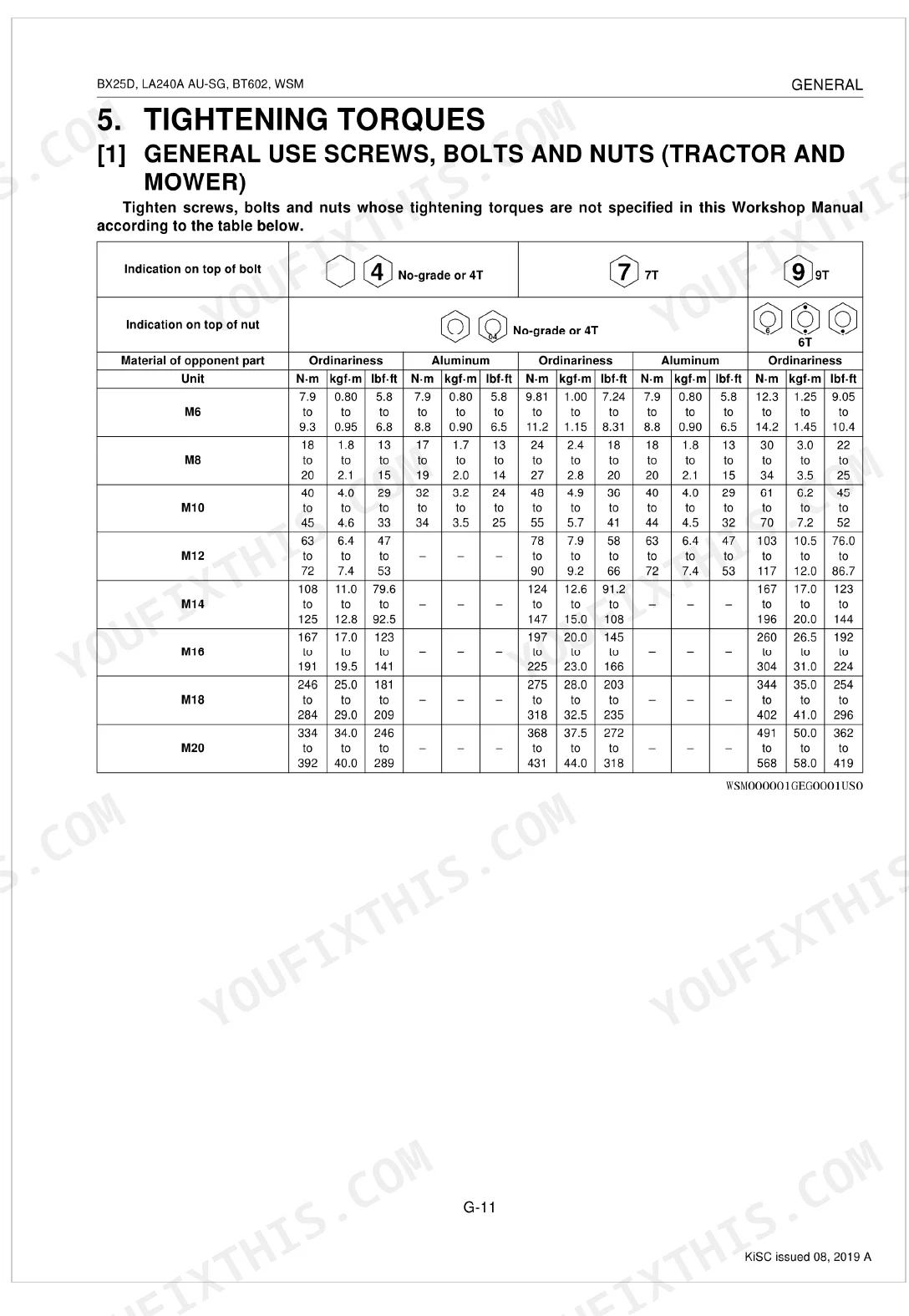
The manual lists torque specs for each mounting bolt. ROPS mounting nuts take 124 to 147 N-m (91.2 to 108 lbf-ft), rear wheel mounting screws 109 to 129 N-m (80.3 to 95.4 lbf-ft), and fuel tank stay bolts and nuts 48 to 55 N-m (36 to 41 lbf-ft).
How do I adjust the HST pedal on a Kubota BX25D?
Start by loosening the locking screw (5). Depress the speed control pedal (3) to the "Forward" or "Reverse" position, release your foot, and adjust the locking screw until the rear axle stops rotating. Set the forward stopper bolt (A) to 17.0 mm (0.669 in.) and the reverse bolt (B) to 17.5 mm (0.689 in.).
Why is the 4-in-1 bucket on a Kubota BX25DLB not working?
A non-working 4-in-1 bucket usually traces to a malfunctioning relief valve, damaged control lever linkage, or a clogged oil filter. For the relief valve, check and adjust its pressure (page 5-S4). A damaged boom cylinder may need repair or replacement (page 7-S9).
How quickly can I access this Kubota BX25DLB-AU, LA240A AU-SG, BT602 manual?
Download the PDF the moment payment clears. The full 411-page searchable Shop Manual is yours instantly, ready to open on a laptop, tablet, or phone right in the shop.
Can I print specific sections of this Kubota BX25DLB-AU, LA240A AU-SG, BT602?
Yes. The PDF carries no DRM restrictions, so print any page or section you need for your shop. Works with any standard printer.
Does this Kubota BX25DLB-AU, LA240A AU-SG, BT602 manual include hydraulic?
Full hydraulic system diagrams are included, covering circuits, valve locations, and hydraulic component specs for the Kubota BX25DLB-AU, LA240A AU-SG, BT602.
Document Quality
This document is a scanned PDF with an OCR layer, allowing you to search and copy the full text. The text quality is consistently crisp and easy to read throughout. Diagrams and illustrations are primarily raster images or photos, but they are clear, and all labels are readable. The pages are clean with no noticeable scan artifacts, stains, or skewed content. There are no notable blank or filler pages beyond the main section dividers.


Reviews
There are no reviews yet.