
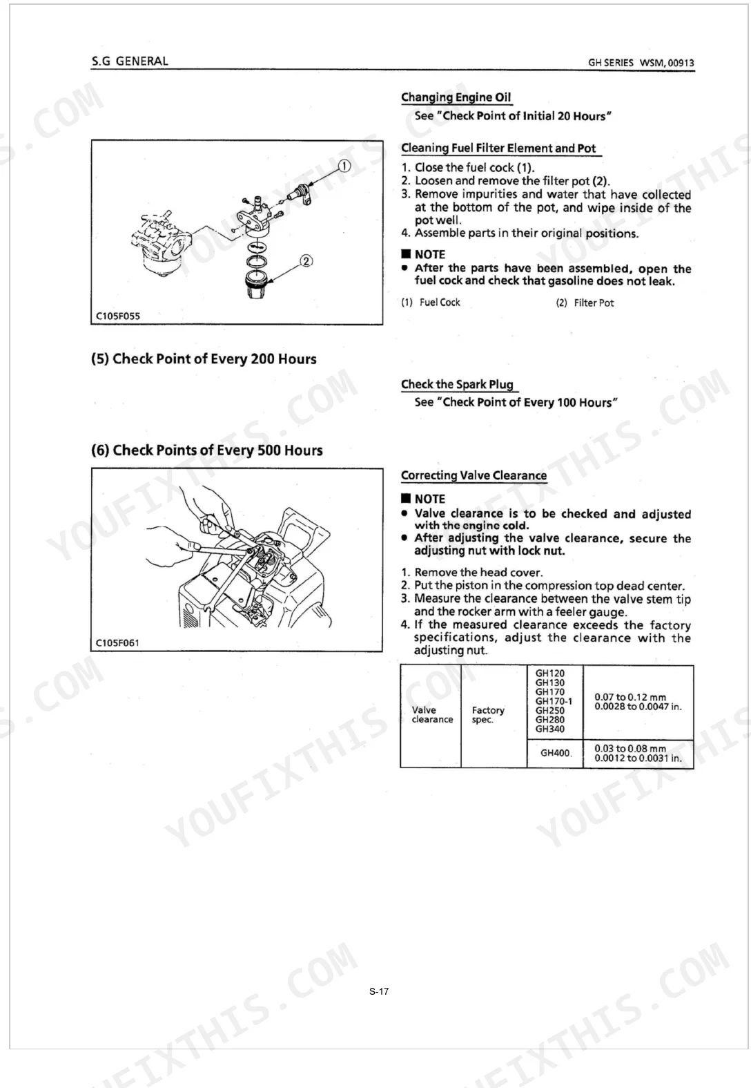
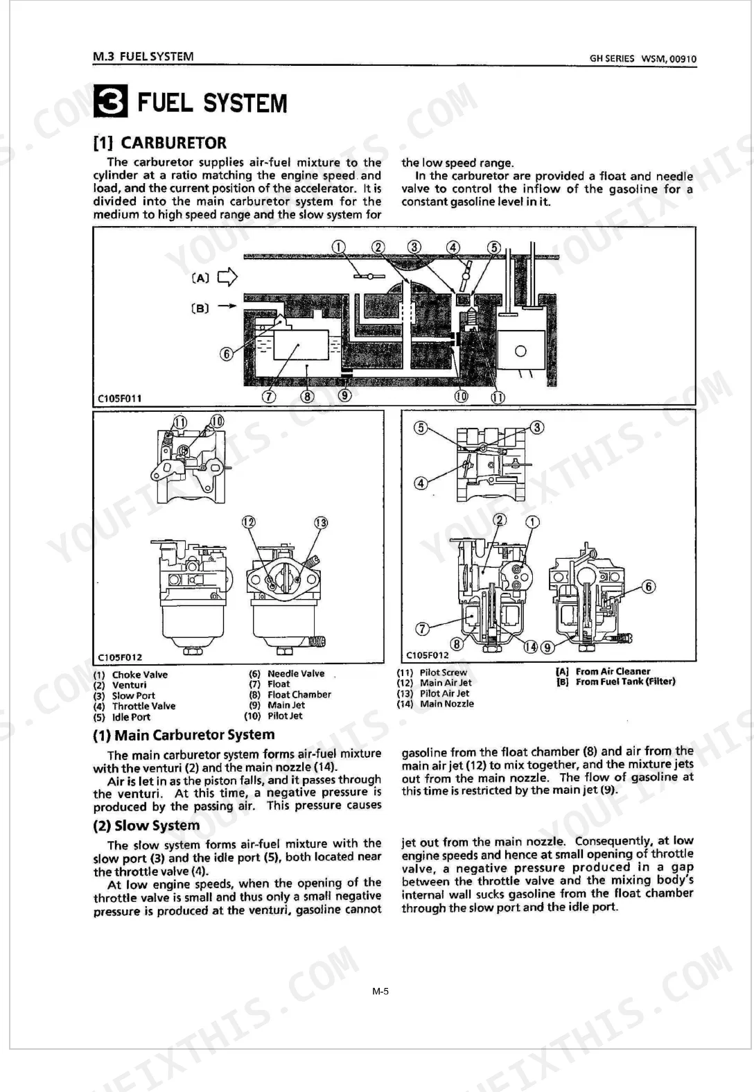
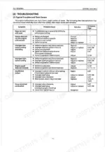
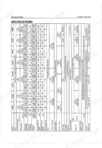
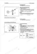
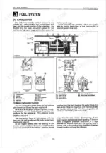
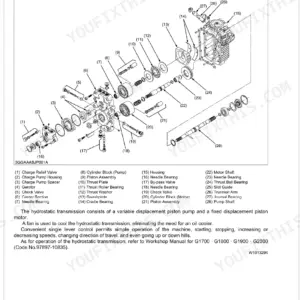
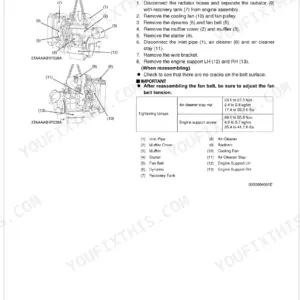
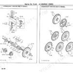
Eight GH gasoline engines, one factory source: the GH120, GH130, GH170, GH170-1, GH250, GH280, GH340, and GH400 all fill these 104 pages (OEM #97897-00915). Twenty-five pages of exploded-view diagrams break down cylinder heads, pistons, connecting rods, and crankshafts, while per-model circuit diagrams label every wire by size and color. Carburetor and governor adjustment, CDI and transistor magnet ignition checks, and the mechanical decompression walkthrough join a troubleshooting chart that traces hard-start symptoms to their root cause. Spark plug torque runs 9.8 to 24.5 N-m across the range; the M8 x 1.25 cylinder head screws on the GH120, GH130, GH170, and GH170-1 pull to 24.5 to 35.3 N-m. Download once, search by keyword, and get the machine running.
What's Inside This Kubota GH120–GH400 Series Manual
| System | Pages | Key Topics |
|---|---|---|
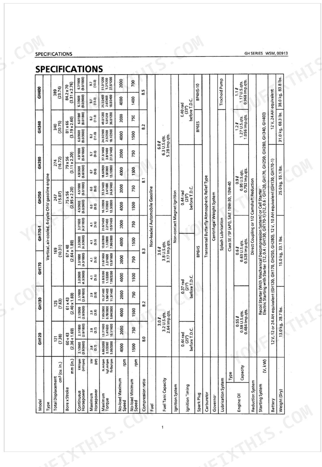
| Specifications | 7 | Engine Specifications (Model, Type, Total Displacement, Bore x Stroke, Continuous Horsepower, Maximum Horsepower, Maximum Torque, No-load Maximum Speed, No-load Minimum Speed, Compression Ratio) |
| Performance Curves | 8-9 | Gh120 (Brake Horsepower, Engine Speed, Fuel Consumption, Torque, Maximum Torque, Maximum Horsepower, Recommended Horsepower) |
| Dimensions | 10-20 | Gh120, Gh130, Gh170, Gh170-1, Gh250 Gh280, Gh340, Gh400, Gh400-2 |
| Feature | 21-22 | Cross Section (High Output and Low Fuel Consumption, Low Vibration and Low Noise), Contrast Between D.Q.P.S.G.I Types and R Type |
| Engine Body (Mechanism) | 23 | Mechanical Decompression System (At Engine: Start, Running) |
| Lubricating System (Mechanism) | 24 | Oil Pump, Relief Valve |
| Fuel System (Mechanism) | 25-27 | Carburetor (Main Carburetor System, Slow System, Float), Governor |
| Ignition System (Mechanism) | 28-30 | Transistor Magnet Ignition Type, CDI Magnet Ignition Type |
| Starting System (Mechanism) | 31-34 | Starter Operation Except for GH340, GH400 (When: Main Switch is Turned to Start, Engine Starts, Starter Switch is Released), Starter Components (Except for GH340, GH400) |
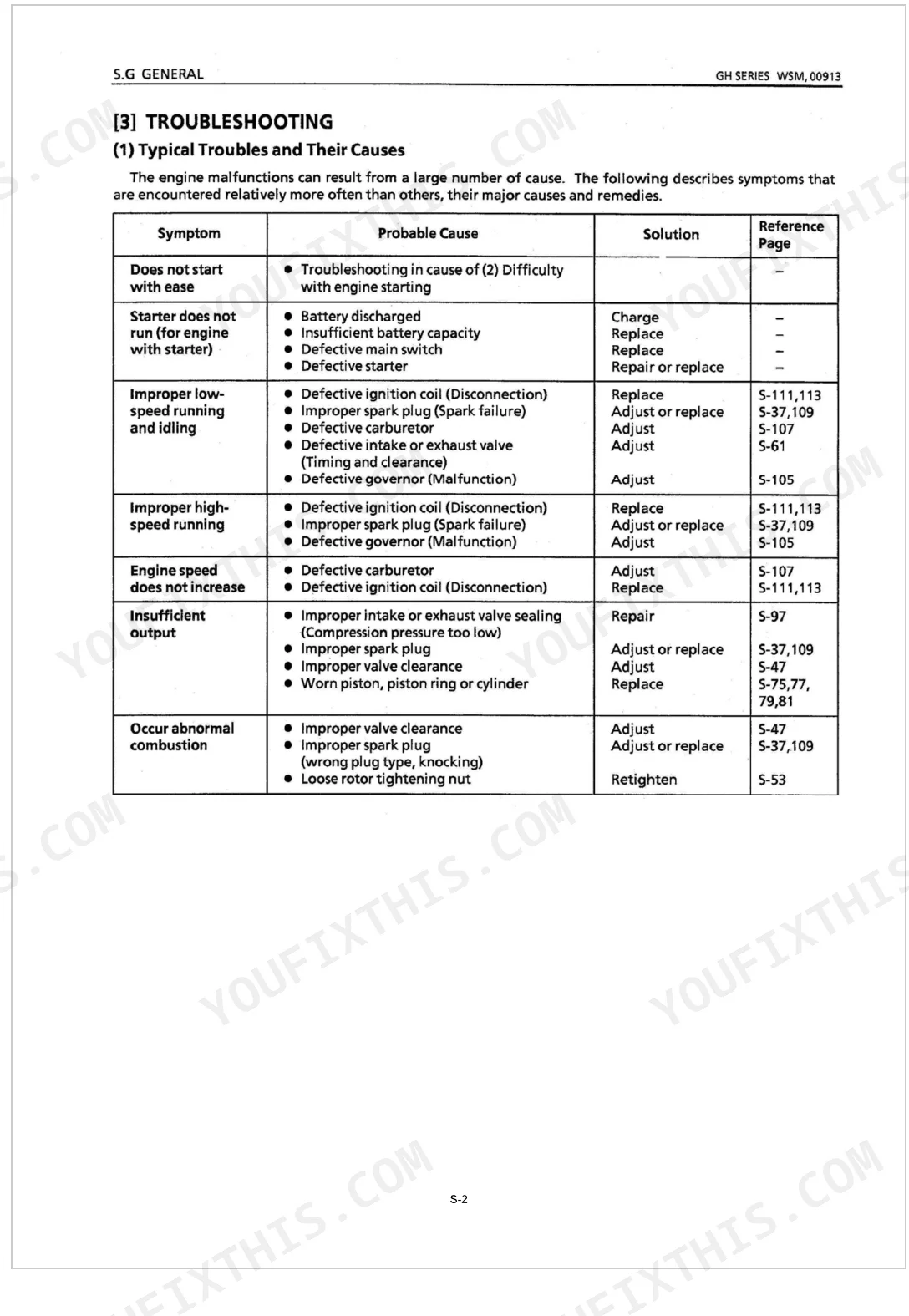
| General | 35-54 | Engine Identification, Troubleshooting (Typical Troubles and Their Causes, in Cause of Difficulty with Engine Starting), Servicing Specifications (Engine Body) |
| Engine Body (Disassembly and Servicing) | 55-82 | Checking and Adjusting, Disassembling and Servicing (External Components, Cylinder Head, Piston, Connecting Rod and Crankshaft, Except for GH400, GH400 Only) |
| Lubricating System (GH400) | 83-84 | Checking, Disassembling and Assembling (Oil Pump, Relief Valve), Servicing (Oil Pump) |
| Fuel System (Disassembly and Servicing) | 85-87 | Checking and Adjusting Carburetor (Engine Speed, Engine Idling Speed), Checking and Adjusting Governor (Governor and Maximum No-load Speed) |
| Ignition System (Disassembly and Servicing) | 88-90 | Checking Spark Plug (Spark Test), Checking Stop Switch (Switch Continuity), Checking Ignition Unit (Transistor Magnet Type, CDI Magnet Type) |
| Starting System (Disassembly and Servicing) | 91-98 | Starter, Disassembling and Assembling (Recoil Starter, Starter), Servicing |
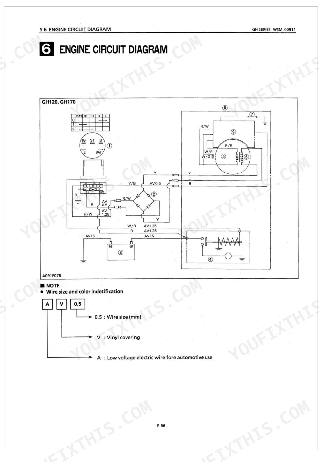
| Engine Circuit Diagram | 99-104 | GH120, GH170 Circuit Diagram (Wire Size and Color Indetification), GH130, GH170-1 GH250 GH280, GH340 GH400 Circuit Diagram (Wire Color), Component List |
Quick Reference Specifications
| Specification | Value | Page |
|---|---|---|
| All Models | ||
| Spark Plug Torque | 9.8 to 24.5 N-m | p. 47 |
| GH120, GH130 | ||
| Rotor Mounting Nut Torque | 29.4 to 49.0 N-m | p. 47 |
| GH120, GH130, GH170, GH170-1 | ||
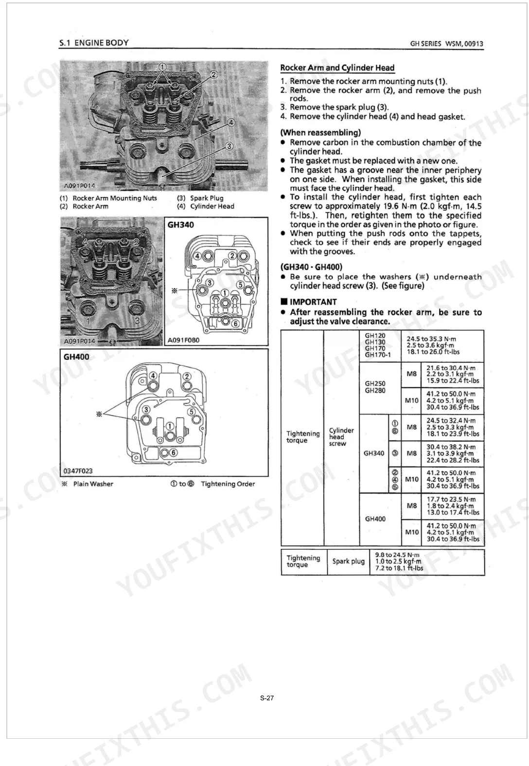
| Cylinder Head Screws Torque (M8 x 1.25) | 24.5 to 35.3 N-m | p. 47 |
| Connecting Rod Screws Torque (M7 x 1.0) | 13.7 to 19.6 N-m | p. 47 |
| Rocker Arm Rock Nut Torque (M6 x 0.5) | 7.8 to 12.7 N-m | p. 47 |
| GH120, GH130, GH170-1 | ||
| Crankcase 2 Screws Torque (M6 x 1.0) | 9.8 to 14.7 N-m | p. 47 |
| GH170, GH170-1 | ||
| Rotor Mounting Nut Torque | 58.8 to 73.6 N-m | p. 47 |
| GH170, GH250, GH280, GH340, GH400 | ||
| Crankcase 2 Screws Torque (M8 x 1.25) | 13.7 to 19.6 N-m | p. 47 |
| GH250, GH280 | ||
| Rotor Mounting Nut Torque | 68.6 to 83.4 N-m | p. 47 |
| Cylinder Head Screws Torque (M8 x 1.25) | 21.6 to 30.4 N-m | p. 47 |
| GH250, GH280, GH340, GH400 | ||
| Cylinder Head Screws Torque (M10 x 1.5) | 41.2 to 50.0 N-m | p. 47 |
| Connecting Rod Screws Torque (M8 x 1.25) | 23.5 to 29.4 N-m | p. 47 |
Kubota GH120–GH400 Series Common Problems This Manual Covers
Kubota GH120 engine cranks over but refuses to start after sitting in cold storage p. 50
Pull the spark plug and check it against page 50. Measure the gap, then bring it to 0.6 to 0.7 mm and scrub carbon off the electrodes. Refit the plug at 9.8 to 24.5 N-m and confirm a strong, blue spark before cranking again.
Manual Section: GeneralEngine starts but surges uncontrollably and stalls when placed under heavy load p. 85
Reset the carburetor pilot screw and recheck the throttle stopper. Page 85 puts D type idling speed between 1400 and 1600 rpm, so dial it into that band. If the surge holds, inspect the fuel lines for restrictions and flush the main system.
Manual Section: Fuel System (Disassembly and Servicing)Persistent misfire and severe loss of power output during continuous high-speed operation p. 45
Slip a feeler gauge into the transistor magnet air gap and read it. Page 45 calls for 0.4 to 0.6 mm, so shift the ignition coil until the gap lands there. Follow up by checking primary and secondary coil resistance to rule out a failing coil.
Manual Section: GeneralLoss of compression and rough idling after long periods of heavy usage p. 38
Lift off the cylinder head and clear carbon from the combustion chamber. Lay a straightedge across the surface and check flatness with a feeler gauge. Once warpage passes the 0.05 mm limit on page 38, resurface or replace the head to bring compression back.
Manual Section: GeneralFrequently Asked Questions
How to reset the governor on a Kubota GH series engine?
Start by loosening the tightening screw at the lower end of the governor lever. With the lever, push the throttle valve fully open, turn the groove on the governor lever shaft fully clockwise using a screwdriver, then tighten the screw in that spot. Run the engine and adjust the high-speed screw until PTO shaft speed reaches 3900 to 4000 rpm (D type) or 1950 to 2050 rpm (G type) with the control lever at maximum. On a GH170, torque the governor lever screw to 6.9 to 15.7 N-m (5.1 to 11.6 ft-lbs).
What are the torque specs for a Kubota GH170 head bolts?
GH170 cylinder head screws are M8 x 1.25 and torque to 24.5 to 35.3 N-m (2.5 to 3.6 kgf-m, 18.1 to 26.0 ft-lbs). Run each screw to roughly 19.6 N-m (14.5 ft-lbs) first, then come back and retighten to the full spec in the order the manual shows.
What are the torque specs for Kubota GH130 connecting rod bolts?
On the GH130, the connecting rod screws use an M7 x 1.0 thread and torque to 13.7 to 19.6 N-m (1.4 to 2.0 kgf-m, 10.1 to 14.5 ft-lbs). Before you reassemble, coat the connecting rod screw and the inner periphery of the big end of the rod with engine oil.
What are the replacement specifications for spark plug?
Gap and plug type both depend on the model. GH120, GH130, GH170, GH170-1, GH250, and GH280 run a 0.6 to 0.7 mm (0.0236 to 0.0276 in.) gap on a BP6HS. The GH340 takes 0.7 to 0.8 mm (0.0276 to 0.0315 in.) on a BP6ES, and the GH400 wants 0.9 to 1.0 mm (0.0354 to 0.0394 in.) on a BP4HS-10. Swap the plug out if the electrode or insulator is cracked or deformed.
How quickly can I access this Kubota GH120–GH400 Series manual after buying?
A 104-page Workshop Manual in searchable PDF, ready the moment your checkout clears. Open it on a computer, tablet, or phone with no shipping wait.
Can I print specific sections of this Kubota GH120–GH400 Series Workshop Manual?
Yes. Print as many copies as you like; there are no restrictions. Plenty of mechanics run off just the section they need and carry it out to the shop floor.
Are hydraulic system diagrams in this Kubota GH120–GH400 Series Workshop Manual?
No. This manual does not include hydraulic system diagrams or schematics. It covers engine specifications, performance curves, wiring diagrams, and mechanical service procedures.
Document Quality
This document is a scanned PDF with an OCR layer, so you can search and copy the full text. The text throughout is crisp and easy to read, ensuring good legibility. Diagrams and illustrations are raster images; most labels are readable, though some fine print in the dimension diagrams might require zooming to see clearly. All pages are clean with no scan artifacts, stains, or skewed content. You will find a few intentionally blank pages (2, 4, 18, 20, 34) which serve as filler.

Reviews
There are no reviews yet.