
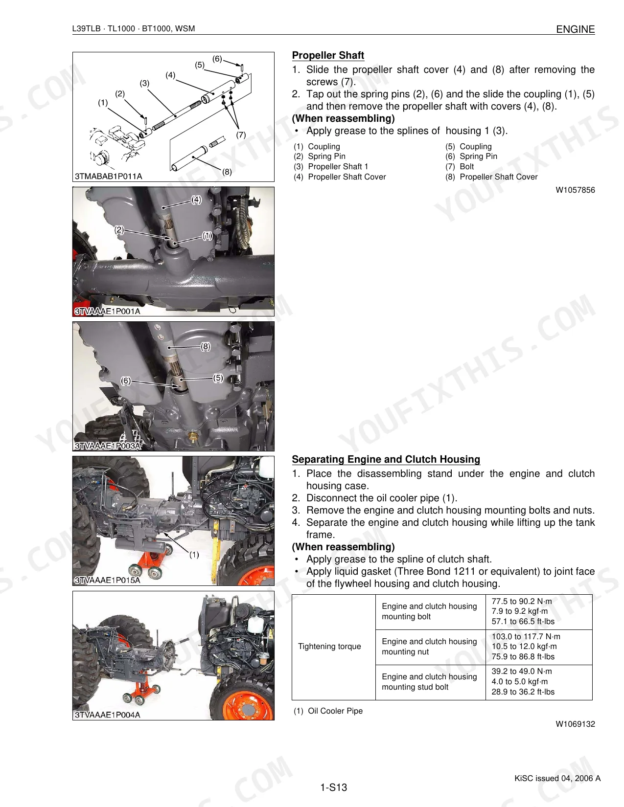
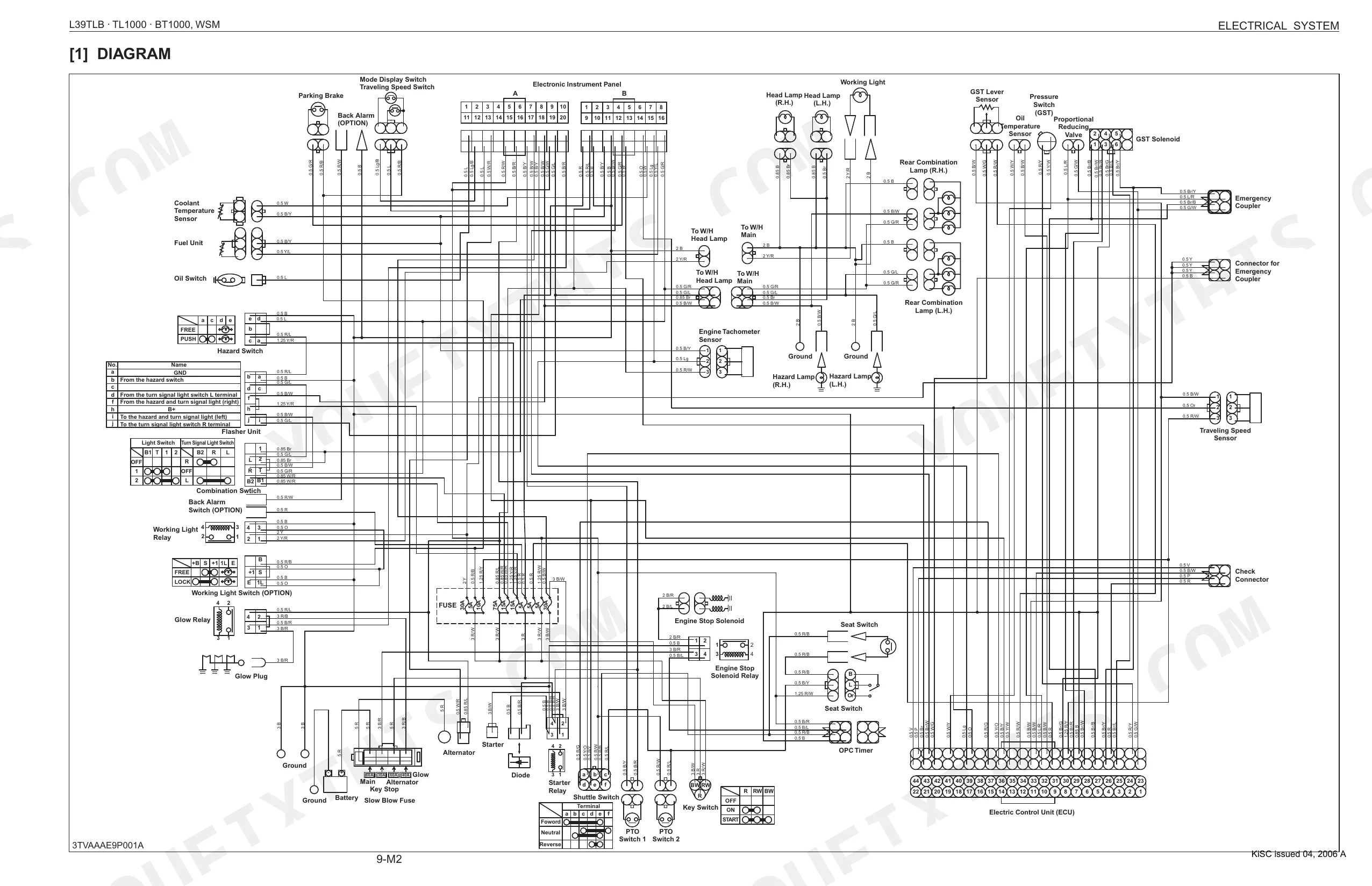
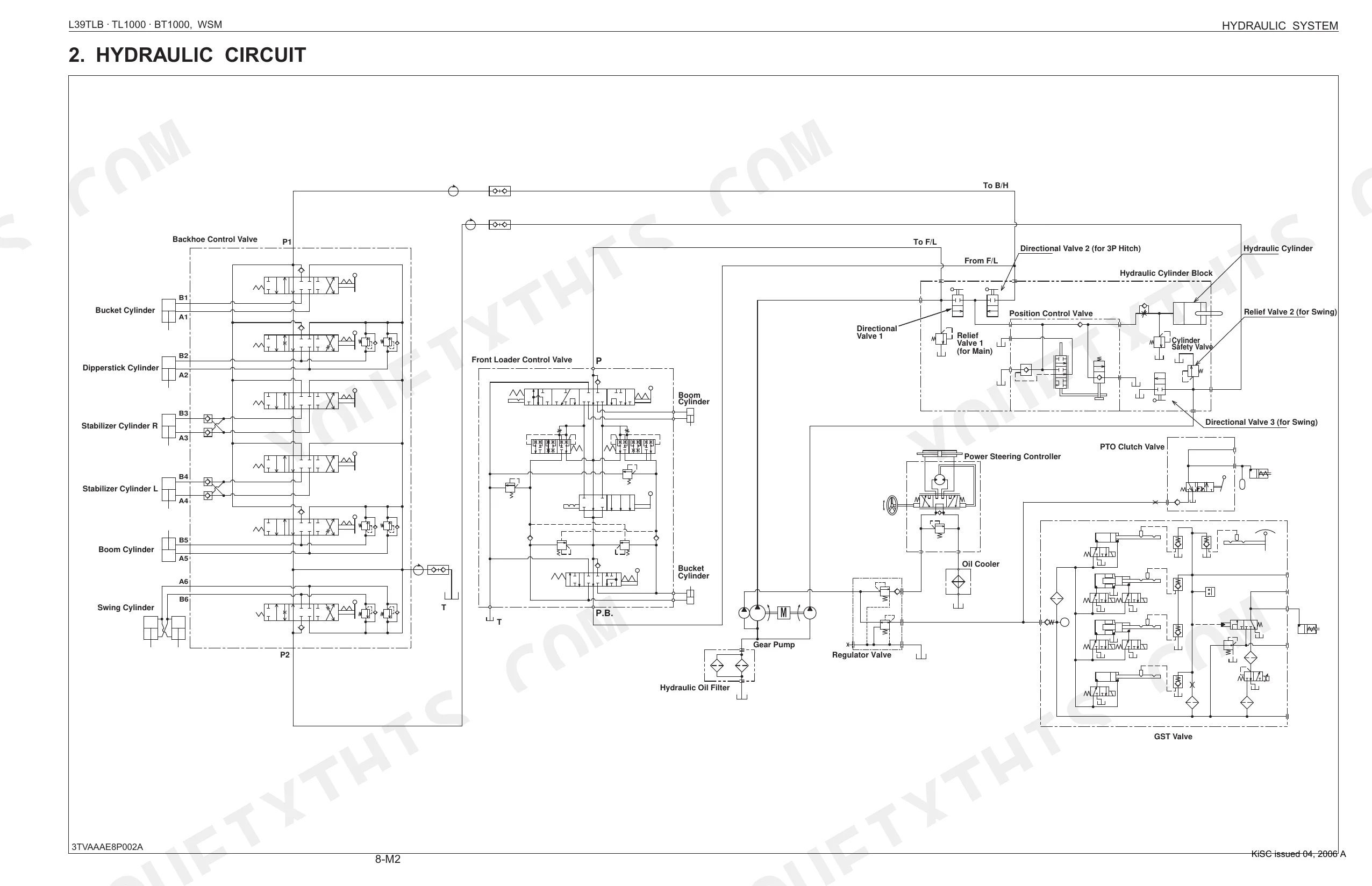
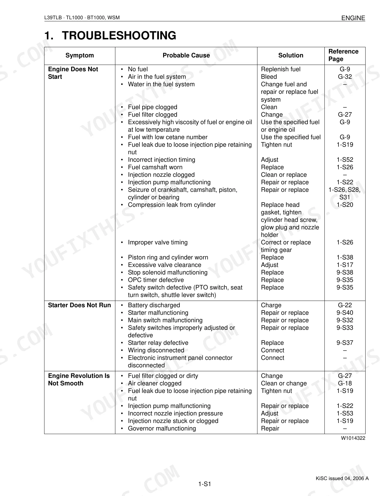
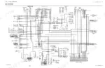
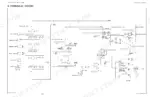
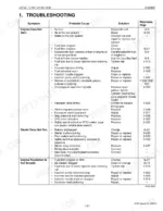
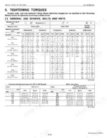
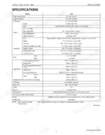
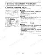
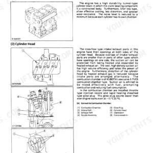
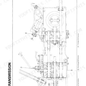
Three machines, one OEM document (#9Y011-13251): the L39 compact tractor, the TL1000 front loader, and the BT1000 backhoe, all covered across 543 pages. The wiring diagrams run the complete electrical control panel circuit; the hydraulic schematics map the loader boom cylinders and the backhoe control valve. It also packs in torque tables, troubleshooting charts for the GST transmission and PTO system, 130 pages of step-by-step service procedures, and exploded-view diagrams spanning every drivetrain and implement section. Need clutch pedal free play? It's 20 to 30 mm. Gear-to-spline clearance? Hold it between 0.030 and 0.078 mm. Both come straight from Kubota's factory specs. Everything is bookmarked by system, so you can search a spec by keyword, pull it up on your phone, and start wrenching.
What's Inside This Kubota L39, TL1000, BT1000 Manual
| System | Pages | Key Topics |
|---|---|---|
| G General | 12-61 | Tractor Identification (Model Name and Serial Numbers, Cylinder Number), Handling Precautions for Electrical Parts and Wiring (Battery, Fuse, Connector, Handling of Circuit Tester) |
| P Preparation | 62-85 | Disassembling and Assembling (Separating Front Loader Assembly, Hydraulic Hoses, Front Loader Assembly, Separating Canopy, Battery, Canopy Assembly, Front Frame, Separating Rear Wheel, ROPS, Step and Floor Seat, Rear Wheel, Fender and Meter Panel, Bonnet, Skirt and Front Guard, Floor Mat, Steering Post Cover and Rear Cover, Clutch Rod and Electric Wiring for Engine Side, Brake Rods, Power Steering Hoses and Shuttle Lever, Front Loader Control Lever and Hoses, Seat and Lever Grip, Differential Lock Rod, PTO Shift Wire and Accelerator Wires, Removing the Tractor Frame) |
| 1 Engine | 86-146 | Engine Body (Piston, Half-Floating Head Cover), Cooling System (Bottom Bypass System), Fuel System, Lubricating System, Servicing Specifications, Checking |
| 2 Clutch | 147-158 | Feature, Servicing Specifications, Checking, Disassembling and Servicing (Checking and Adjusting, Disassembling and Assembling) |
| 3 Transmission | 159-233 | Characteristic and System Outline, Power Train, Electrical Control System (Construction and Function Components) |
| 4 Rear Axle | 234-242 | Structure, Checking, Disassembling and Servicing (Disassembling and Assembling) |
| 5 Brakes | 243-256 | Linkage, Operation, Servicing Specifications, Checking, Disassembling and Servicing (Brake: Pedal, Case) |
| 6 Front Axle | 257-276 | Structure, Servicing Specifications, Checking, Disassembling and Servicing (Checking and Adjusting, Disassembling and Assembling) |
| 7 Steering | 277-286 | Hydraulic Circuit, Structure, Checking, Disassembling and Servicing (Steering: Controller, Cylinder, Linkage) |
| 8 Hydraulic System | 287-334 | Function of Component Parts (Hydraulic Pump, Position Control Linkage, Directional Valve, Relief Valve, Hydraulic Cylinder), Others (Control Valve, Cylinder Safety Value) |
| 9 Electrical System | 335-414 | Wiring Diagram, Electronic Control Panel (System Outline and Electrical Circuit, Construction and Function of Components, Control System), Starting System |
| 10 Front Loader | 415-483 | Hydraulic System (Structure, Operation, Overload Relief Valve, Boom Cylinder and Bucket Cylinder) |
| 11 Backhoe | 484-543 | Hydraulic System (Hydraulic Circuit, Control Valve, Hydraulic Cylinder) |
Every system also includes tightening torques and troubleshooting.
Quick Reference Specifications
| Specification | Value | Page |
|---|---|---|
| BT1000 | ||
| Backhoe main frame mounting pins torque | Not explicitly found with a numerical value for the main attachment pins of the backhoe to the tractor frame. The manual describes the mounting process but does not specify a torque for these pins. | p. 526 |
| L39 | ||
| Clutch Pedal Free play (Factory Spec) | 20 to 30 mm (0.79 to 1.18 in.) | p. 152 |
| Clutch Disc Boss to Gear Shaft Backlash (Allowable Limit) | 2.0 mm (0.079 in.) | p. 152 |
| Gear to Spline Clearance (Factory Spec) | 0.030 to 0.078 mm (0.00118 to 0.00307 in.) | p. 193 |
| Gear to Spline Clearance (Allowable Limit) | 0.2 mm (0.008 in.) | p. 193 |
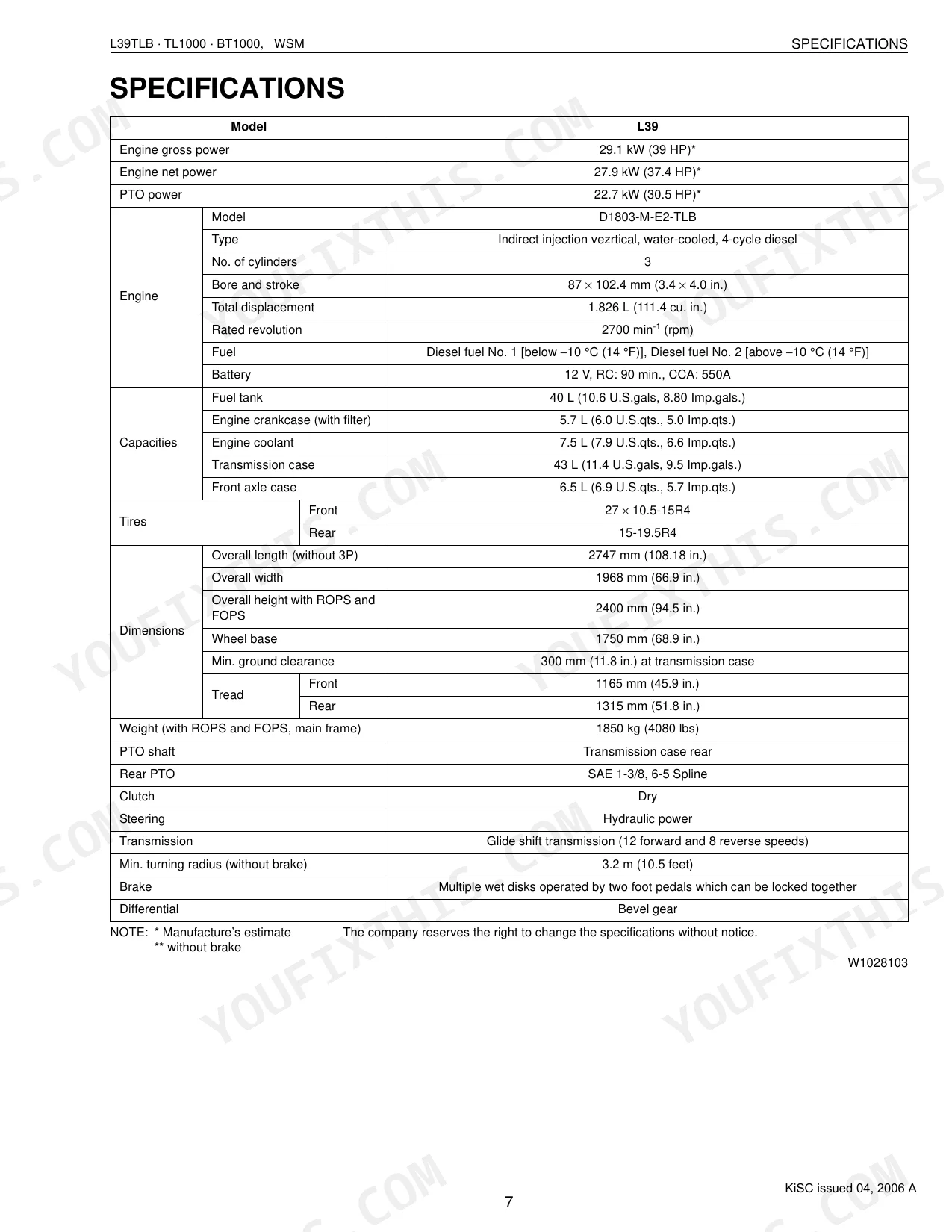
| Engine gross power | 29.1 kW (39 HP) | p. 9 |
| All Models | ||
| Fuel tank capacity | 40 L | p. 22 |
| Engine crankcase (with filter) capacity | 5.7 L | p. 22 |
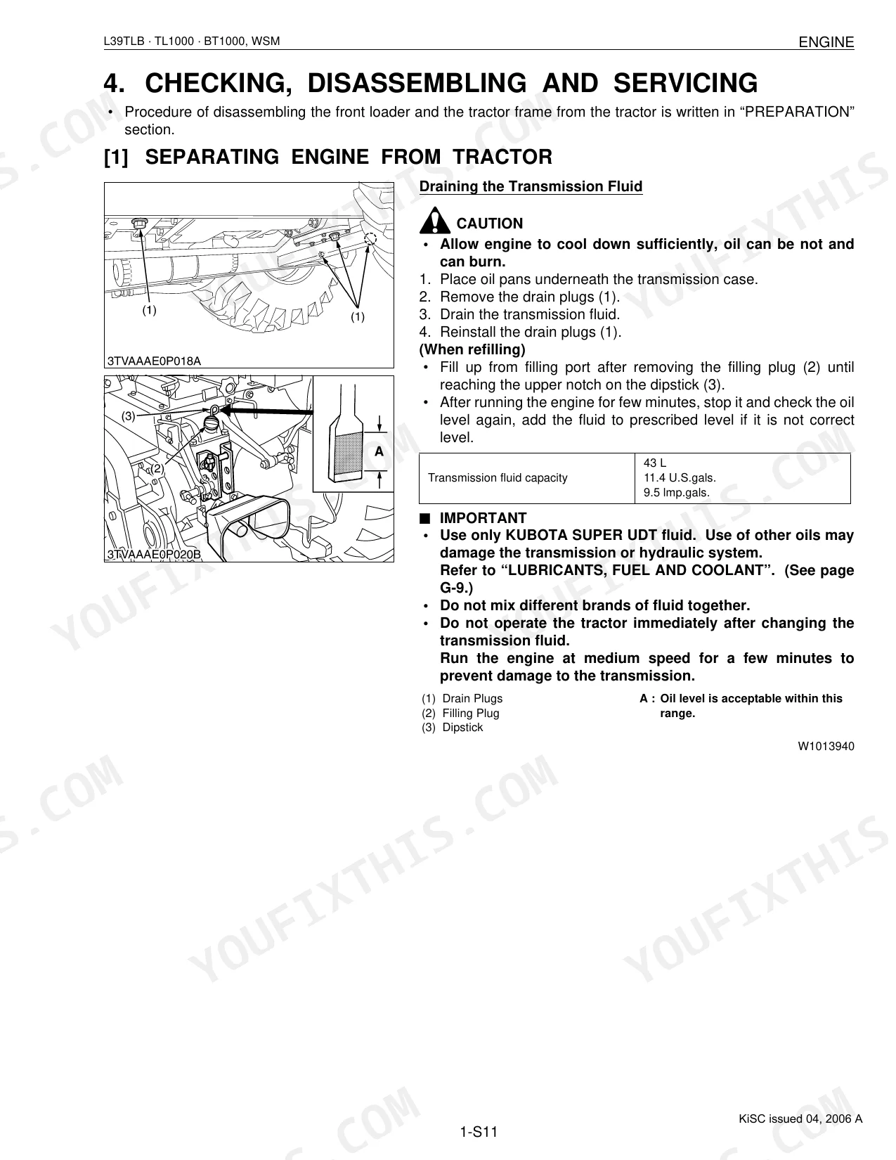
| Transmission case capacity | 43 L | p. 22 |
| Front axle case capacity | 6.5 L | p. 22 |
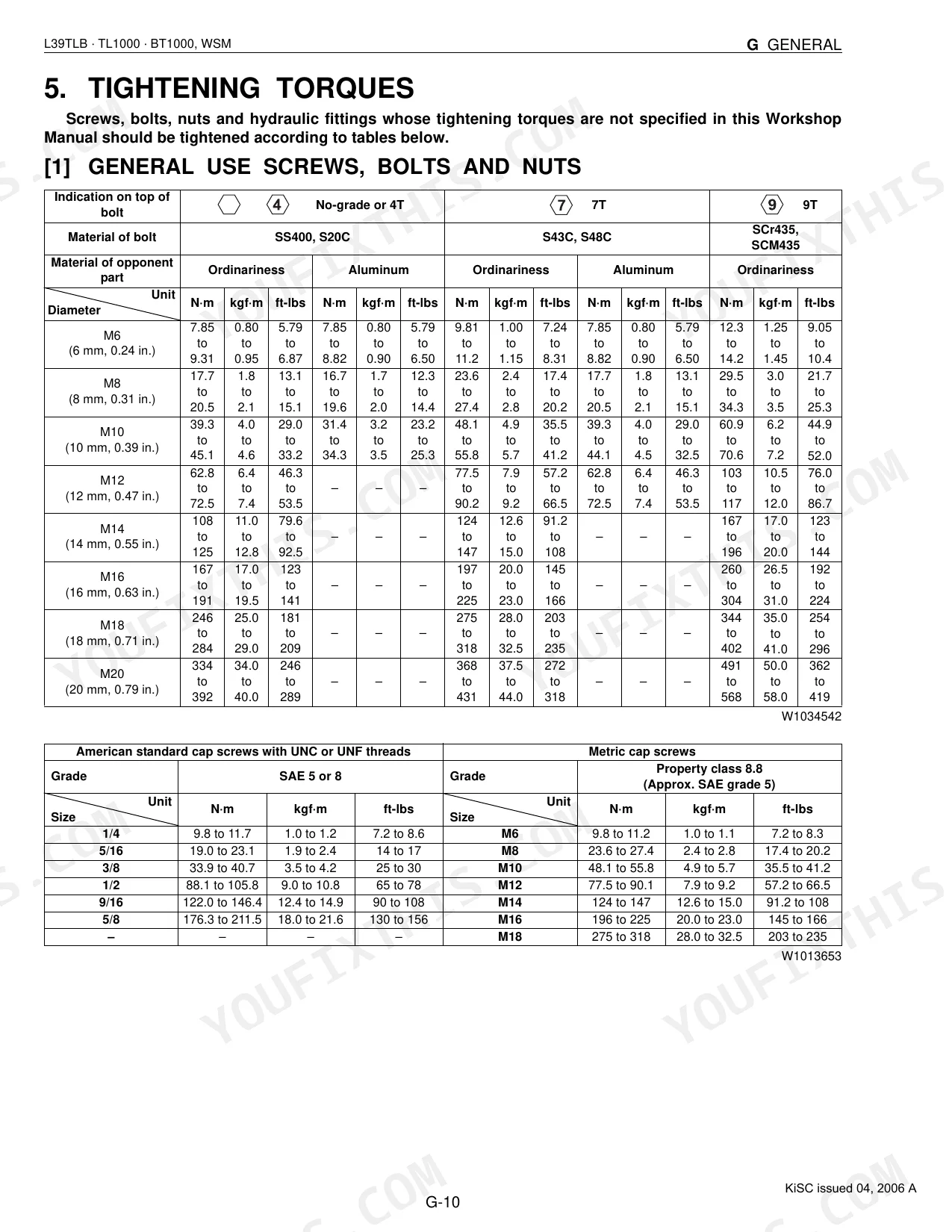
| General screw/bolt tightening torque (M10, 4T) | 39.3 to 45.1 N·m | p. 23 |
| Clutch pedal free travel | 20 to 30 mm | p. 152 |
Kubota L39, TL1000, BT1000 Common Problems This Manual Covers
Kubota L39 stalls immediately when shifted into forward or reverse, engine dies p. 152
Start at the clutch pedal free travel; spec is 20 to 30 mm (page 152). If it falls within range, pull the clutch assembly and inspect disc surface-to-rivet depth (allowable limit: 0.3 mm) and diaphragm spring mutual difference (allowable limit: 0.5 mm). Full clutch diagnosis procedures begin at page 147.
Manual Section: ClutchTransmission shifts hard or grinds, gears clash when selecting range under load
Check the transmission fluid level and top up to the 43 L capacity if it's low. Next, inspect shift fork-to-shifter gear groove clearance (factory spec: 0.20 to 0.40 mm, allowable limit: 0.8 mm). If the GST panel throws an error code, cross-reference the electrical diagnosis chart before any disassembly.
Manual Section: TransmissionHydraulic implement won't rise or lifts very slowly, rear three-point stays down p. 290
Verify the hydraulic fluid level; transmission case capacity is 43 L (page 22). Look for kinked or collapsed hoses along the lift circuit, then read the control valve and position control linkage against the hydraulic schematic on page 290 to trace pressure flow and isolate whether the fault sits in the pump, relief valve, or cylinder.
Manual Section: Hydraulic SystemEngine won't start or cranks very slowly, especially in cold weather conditions
Measure battery voltage; alternator no-load output must exceed 14 V (page 368). Inspect the battery terminals for corrosion and confirm the 40 L fuel tank has supply. If the engine cranks but won't fire, work through the no-start diagnosis procedures to isolate a fuel, air, or electrical fault.
Manual Section: EngineFront loader boom drops under load, won't hold position after raising bucket p. 415
Inspect every boom-circuit hose fitting for seepage; wet connections point to internal bypass. Check the overload relief valve per the Front Loader hydraulic section starting at page 415. With transmission fluid at the full 43 L mark, if the boom still bleeds down under static load, pull the control valve and test the cylinder seals before ordering parts.
Manual Section: Front LoaderAll backhoe functions suddenly inoperative after hard use, no hydraulic cylinder response p. 484
Confirm tractor hydraulic supply is reaching the attachment; check that all backhoe hoses are fully seated and the remote circuit valve is open. Inspect the fluid level (transmission case capacity: 43 L). Trace the backhoe hydraulic circuit on page 484; if all functions die at once, suspect a main relief valve failure rather than individual cylinder faults.
Manual Section: BackhoeFrequently Asked Questions
How do I reset the Kubota L39/TL1000/BT1000 hydraulics or loader controls?
To set the front loader's self-leveling, rest the bucket or pallet fork flat on the ground and raise the boom to full height. If the back tilt angle falls outside 0° to 3°, turn the raising adjuster. Once adjusted, hold the display mode switch down for more than 2 seconds to save the setting.
What are the torque specs for the Kubota L39 loader or backhoe mounting hardware?
On the front loader, torque the front-to-loader-frame mounting bolt and nut (M14 9T) to 166.7 to 196.1 N·m (17.0 to 20.0 kgf·m, 123 to 144 ft-lbs). The backhoe's hydraulic-hose-to-swing-cylinder retaining nut (11/16) calls for 22 to 25 N·m (2.3 to 2.5 kgf·m, 16 to 19 ft-lbs).
What do error codes on a Kubota L39/TL1000/BT1000 mean?
Each LCD error code points to a specific fault. ERROR-20, for instance, is a communication error between the ECU and the electronic instrument panel; check the fuse, ECU connector, or communication line to clear it. ERROR-30 flags an ECU memory device failure and means the ECU needs replacing.
Why is the L39 curl/tilt function slow or weak?
When the curl/tilt function (bucket speed) goes slow or weak, the usual culprits are a worn or damaged bucket cylinder tube or piston rings, oil leaking from pipe joints, or relief valve setting pressure set too low. Low transmission fluid or a damaged inlet pipe O-ring can add to it as well.
How will I receive this Kubota L39, TL1000, BT1000 Workshop Manual?
Download the full 543-page searchable Workshop Manual right after checkout. It opens on any device, from the laptop at your desk to your phone in the field.
Am I able to print pages from this Kubota L39, TL1000, BT1000 manual?
None at all. The PDF ships DRM-free, so print whatever sections you want to carry out to the shop. Standard letter or A4 paper both work.
Does this Kubota L39, TL1000, BT1000 manual include wiring diagrams?
Yes. The manual includes complete wiring diagrams covering every electrical circuit, the harness routing, and connector pinouts for the Kubota L39, TL1000, BT1000.
Document Quality
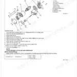
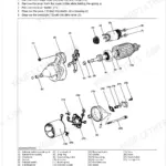
This is a native digital PDF document, allowing you to search and copy the full text content. All text is crisp, clear, and very easy to read throughout the manual. Diagrams and illustrations are high-quality vector graphics, remaining sharp and fully readable even when zoomed in. Pages are clean with no scan artifacts, though there are several notable blank filler pages separating sections.


Reviews
There are no reviews yet.