


Tracking down the exact OEM part number before calling the dealer saves time and frustration. This 42-page Kubota LA302 Loader Parts Catalog delivers exploded-view diagrams and lists for the chassis, brace, boom, front attachments, control lever, and the complete hydraulic system. It covers both 3-position and 4-position control valve types. Serial number breakpoints (S.No. ≤19999 and S.No. ≥50001) clarify exactly which component fits your specific machine. Boom and bucket cylinder sections break down into individual seals, rods, pistons, fittings, and plugs. Factory specifications are included, noting the main frame assembly (Part No. 7J043-90110) weighs 81 kgf, while the alternate variant (Part No. 7J043-90182) weighs 92 kgf. Stop playing phone tag with the parts counter. The file is fully bookmarked by section and searchable on any device.
What's Inside This Kubota LA302 Loader Parts Manual
| System | Pages | Key Topics |
|---|---|---|
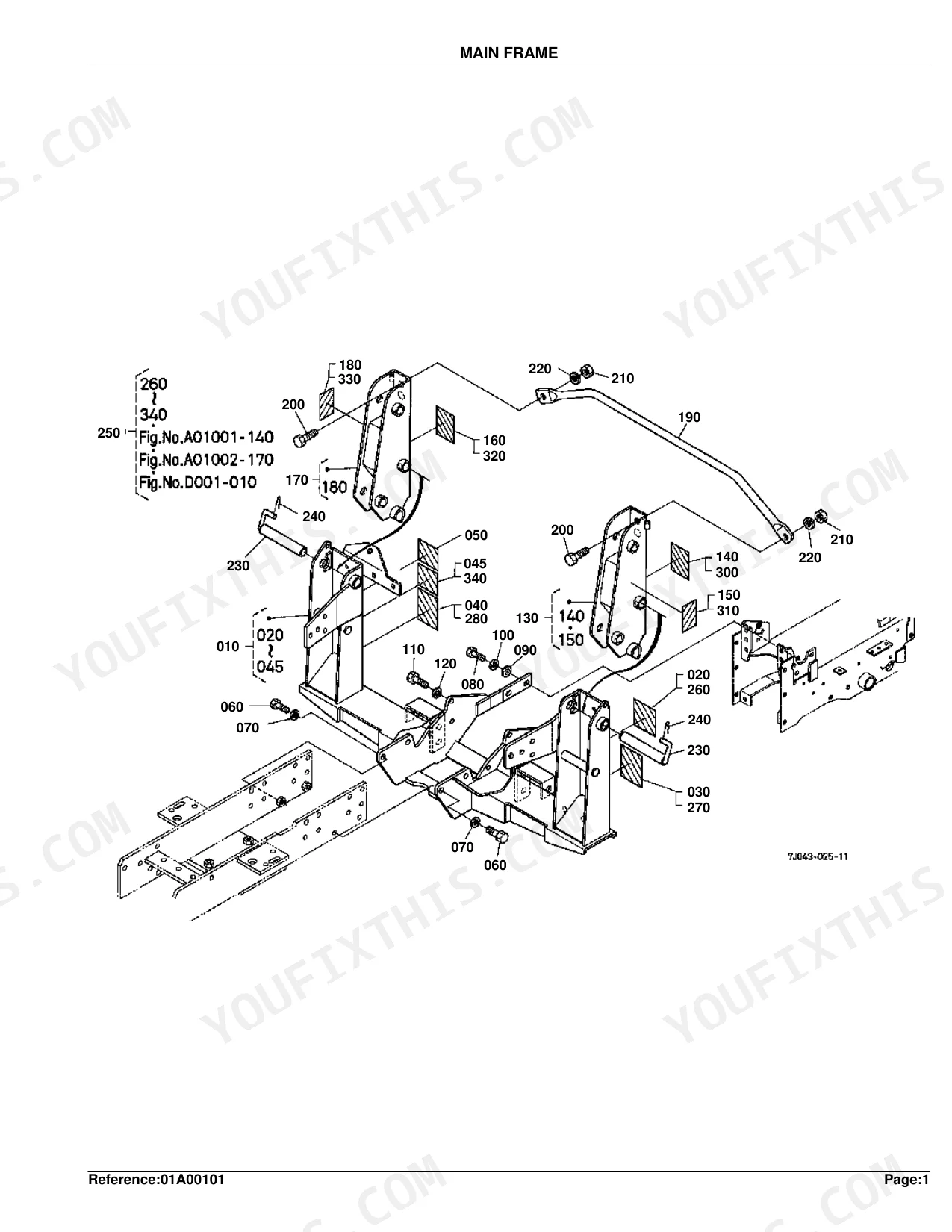
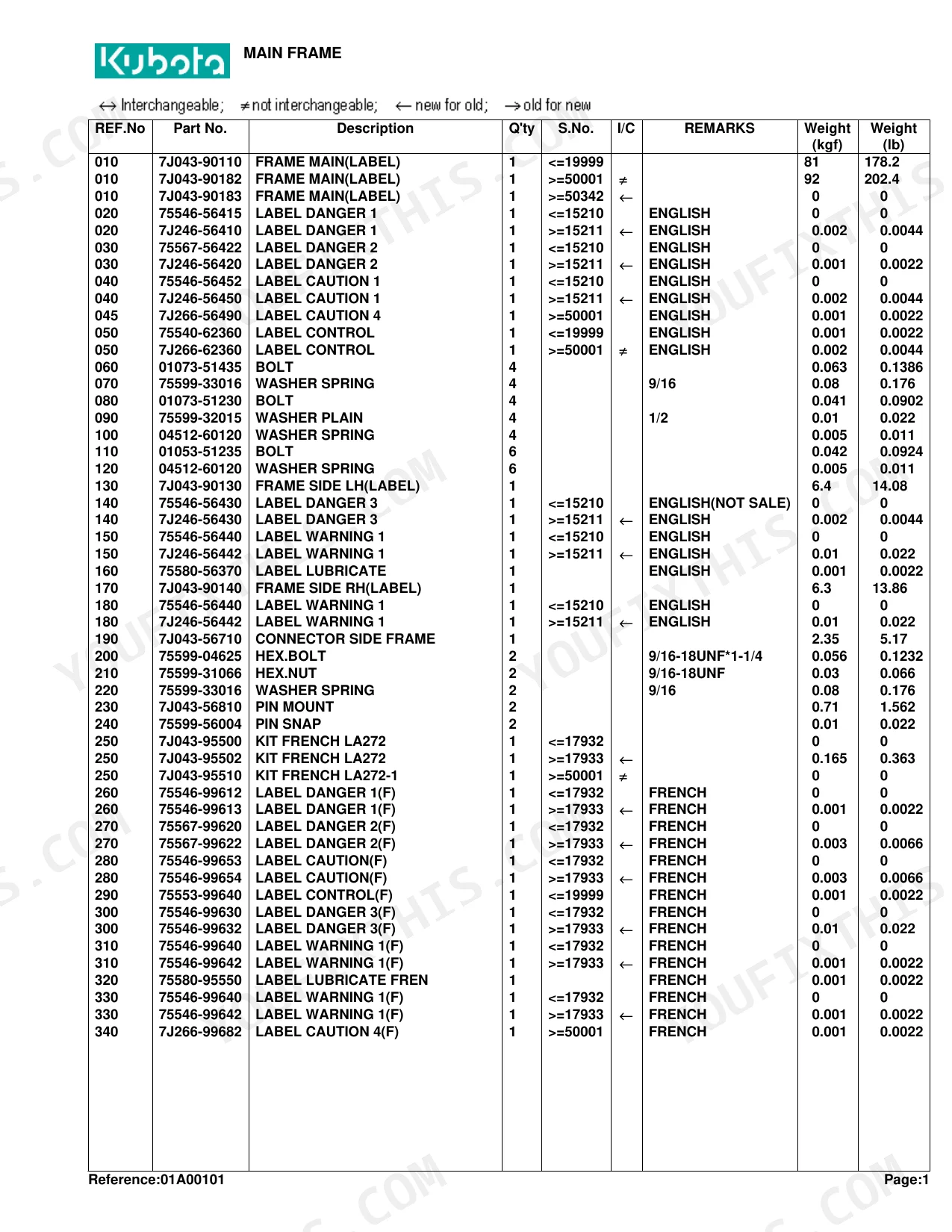
| Main Frame | 4-6 | Main Frame Components Diagram, Old Part Diagram, Main Frame Parts List |
| Brace | 7-8 | Assembly Parts, Fasteners for Brace, Comp Guard Front Parts |
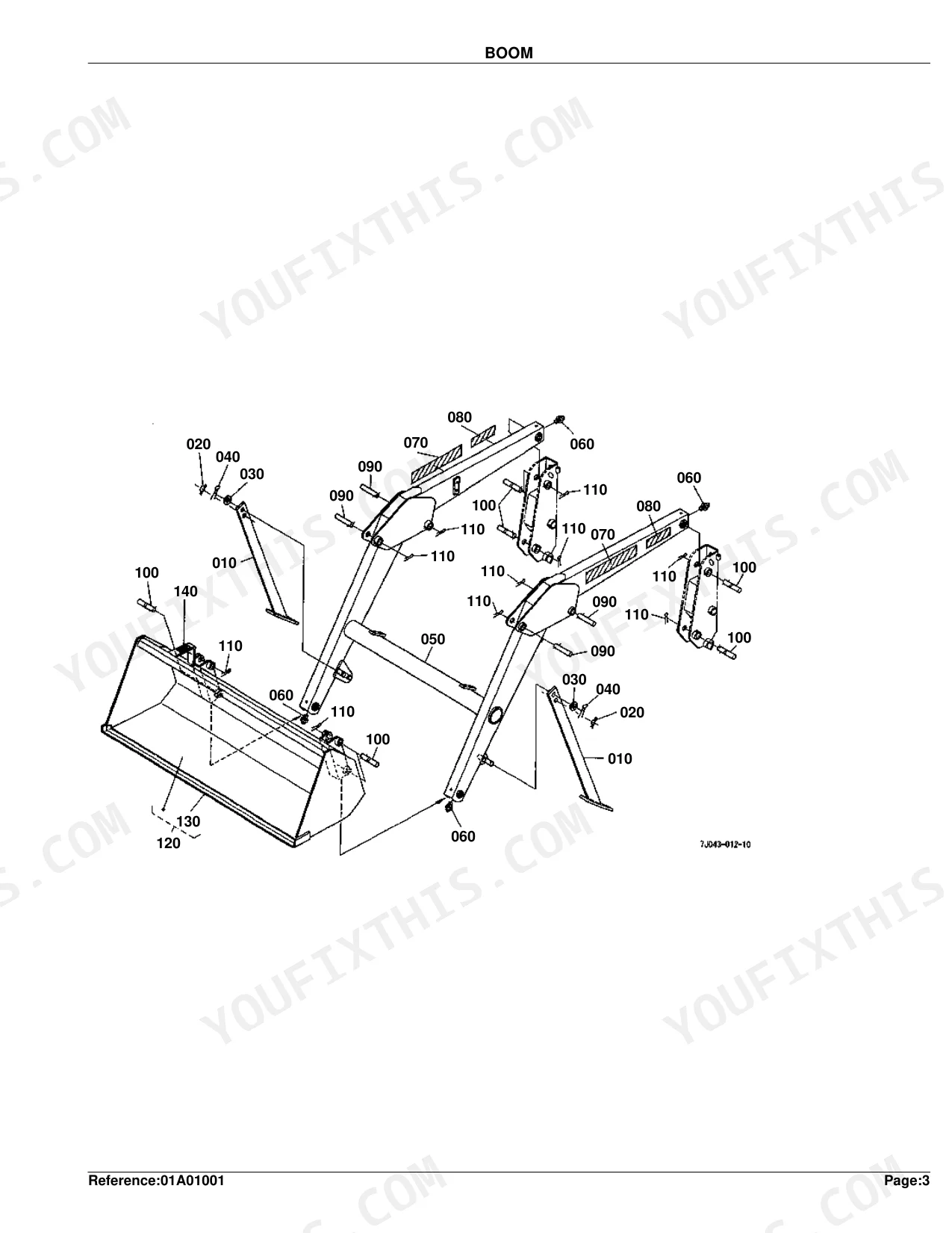
| Boom | 9-10 | Assembly Parts, Fasteners and Pins, Labels and Bucket Components |
| Control Valve | 11-16 | Control Valve Diagram (3 Position Valve Type), Control Valve Diagram (4 Position Valve Type) |
| Control Valve [Component Parts] | 17-22 | Component Parts List (3 Position Valve Type), Component Parts List (4 Position Valve Type) |
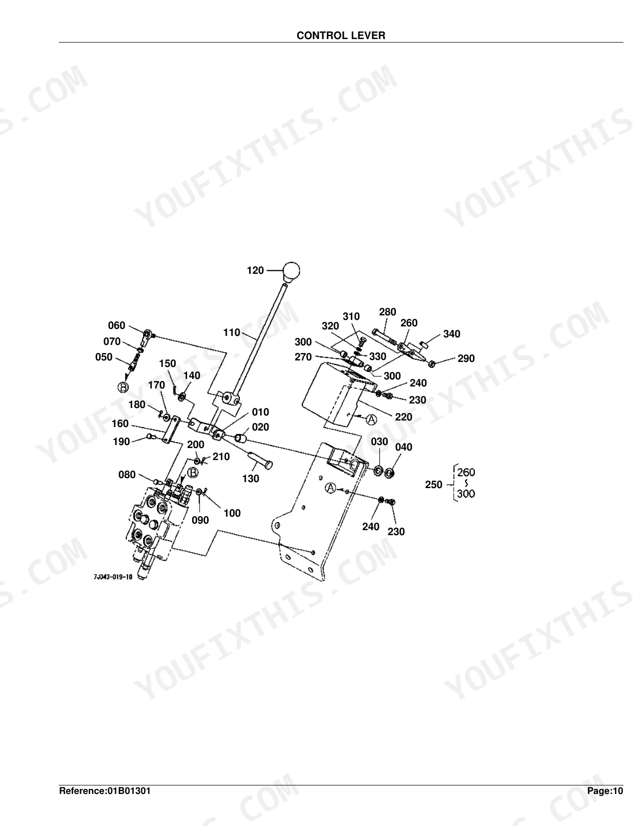
| Control Lever | 23-26 | Control Lever Diagram (S.No. <=19999), Control Lever Parts List (S.No. <=19999), Control Lever Diagram (S.No. >=50001), Control Lever Parts List (S.No. >=50001) |
| Cylinder/Hydraulic Hose | 27-28 | Cylinder Components, Hydraulic Hoses, Band Code |
| Hydraulic Hose(Hyd.Outlet Block) | 29-30 | Hydraulic Hoses, Coupler and Plugs, Sleeve and Band Code |
| Hydraulic Tube | 31-32 | Hydraulic Tubes, Clamp and Fasteners |
| Cylinder (Boom)[Component Parts] | 33-34 | Tube Components, Rod, Head, Piston, and Nut Components, Seal, Fittings, and Plugs |
| Cylinder (Bucket)[Component Parts] | 35-36 | Tube Components, Rod, Head, Piston, and Nut Components, Seal, Fittings, and Plugs |
| Hydraulic Block | 37-41 | Hydraulic Block Diagram (S.No. <=19999), Hydraulic Block Parts List (S.No. <=19999), Hydraulic Block Diagram (S.No. >=50001), Hydraulic Block Parts List (S.No. >=50001), Accessories and Service Parts Diagram |
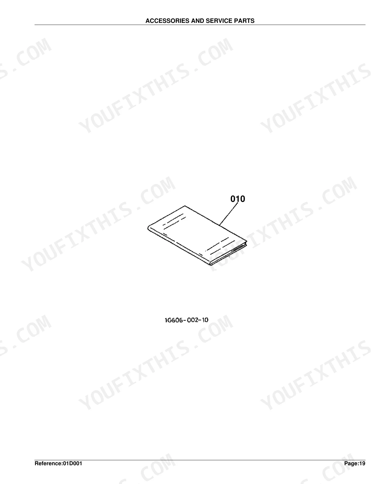
| Accessories and Service Parts | 42 | Operator's Manual English, Operator's Manual French |
Quick Reference Specifications
| Specification | Value | Page |
|---|---|---|
| Main Frame (Part No. 7J043-90110) Weight | 81 kgf | p. 6 |
| Main Frame (Part No. 7J043-90182) Weight | 92 kgf | p. 6 |
| Hex.Bolt (Part No. 75599-04625) Size | 9/16-18UNF*1-1/4 | p. 6 |
| Hex.Nut (Part No. 75599-31066) Size | 9/16-18UNF | p. 6 |
| Brace (Part No. 75536-57400) Weight | 21 kgf | p. 8 |
| Hex.Bolt (Part No. 75599-04630) Size | 9/16-18UNF*1-1/2 | p. 8 |
| Hex.Bolt (Part No. 75599-04530) Size | 1/2-20UNF*1-1/2 | p. 8 |
| Boom (Part No. 7J043-58010) Weight | 96 kgf | p. 10 |
| Fitting Grease (Part No. 75599-81520) Thread | 1/4-28T.T. | p. 10 |
| Stay Valve (Part No. 75536-66110) Weight | 2.4 kgf | p. 12 |
| Cylinder 1 (Part No. 75536-63010) Weight | 6.3 kgf | p. 28 |
| Hose 8 Hydraulic (Part No. 75532-66610) Weight | 0.25 kgf | p. 28 |
Kubota LA302 Loader Common Problems This Manual Covers
Boom will not lower unless float is engaged and normal lower action feels stuck p. 11
Review the Control Valve breakdown on page 11 to spot sticking components. Find the correct replacement detent kits and spool seals. Before ordering, verify the Stay Valve (Part No. 75536-66110), listed at 2.4 kgf on page 12, matches your assembly.
Manual Section: Control ValveLoader responds intermittently with hydraulic fluid leaks at the quick disconnects p. 27
Examine the cylinder and hydraulic hose diagrams on page 27 to isolate leaking couplers. Check the parts list on page 28 for the correct Hose 8 Hydraulic (Part No. 75532-66610) replacement, weighing 0.25 kgf. Secure new O-rings to seal the connections.
Manual Section: Cylinder/Hydraulic HoseCracked main loader arms and worn attachment pins require exact replacement numbers p. 9
Consult the boom and attachment diagram on page 9 to replace worn hardware. Identify the required bucket pins, fasteners, and safety labels. Confirm the correct main Boom (Part No. 7J043-58010), listed at 96 kgf on page 10, to restore structural integrity.
Manual Section: BoomMissing mounting hardware for the front comp guard and main loader frame p. 7
Study the assembly parts for the comp guard front components on page 7. Cross-reference the required fasteners against the parts list to lock down the frame. Ensure the Brace (Part No. 75536-57400), weighing 21 kgf on page 8, is secured with the specified high-strength bolts.
Manual Section: BraceFrequently Asked Questions
What are the replacement specifications for Hydraulic hoses?
The manual provides part numbers and weights for various hydraulic hoses. For example, HOSE 8 HYDRAULIC, Part No. 75532-66610, has a weight of 0.25 kgf (0.55 lb). HOSE 9 HYDRAULIC, Part No. 75536-66620, weighs 0.26 kgf (0.572 lb), and HOSE 10 HYDRAULIC, Part No. 75532-66630, weighs 0.18 kgf (0.396 lb).
Document Quality
This document is a scanned PDF with an OCR layer, allowing you to search and copy text throughout. The text quality is crisp and easy to read on all pages. Diagrams and illustrations are clear raster images, and their labels are readable, though they may pixelate if zoomed in very closely. The pages are clean with no significant scan artifacts, stains, or marks, although a few pages exhibit minor skewing. There are no notable blank or filler pages present in this document.


Reviews
There are no reviews yet.