


All 44 pages of this Kubota LA434 Operator Manual focus on one thing: running your front loader safely and keeping it in the field. Inside you get 12 pages of step-by-step operating procedures, from filling the bucket and float control to loading from a bank, backfilling, and running pallet forks or a snow blade. A 5-page safety section covers danger, warning, and caution labels before your first lift, and the maintenance chapter maps your service schedule: daily checks, every-50-hour hardware re-tightening, and transmission fluid service. Torque the front axle frame M14 mounting bolts to 150 N-m (110 ft-lbs) and the main frame (Clutch housing) M12 bolts to 80.0 N-m (59.0 ft-lbs). Your loader is sitting idle while you chase specs on a forum. Download now, jump to any bookmarked section, and get back to work.
What's Inside This Kubota LA434 Operator Manual
| System | Pages | Key Topics |
|---|---|---|
| Safe Operation | 6-10 | Before Operating the Loader, Danger, Warning and Caution Labels, Care of Danger |
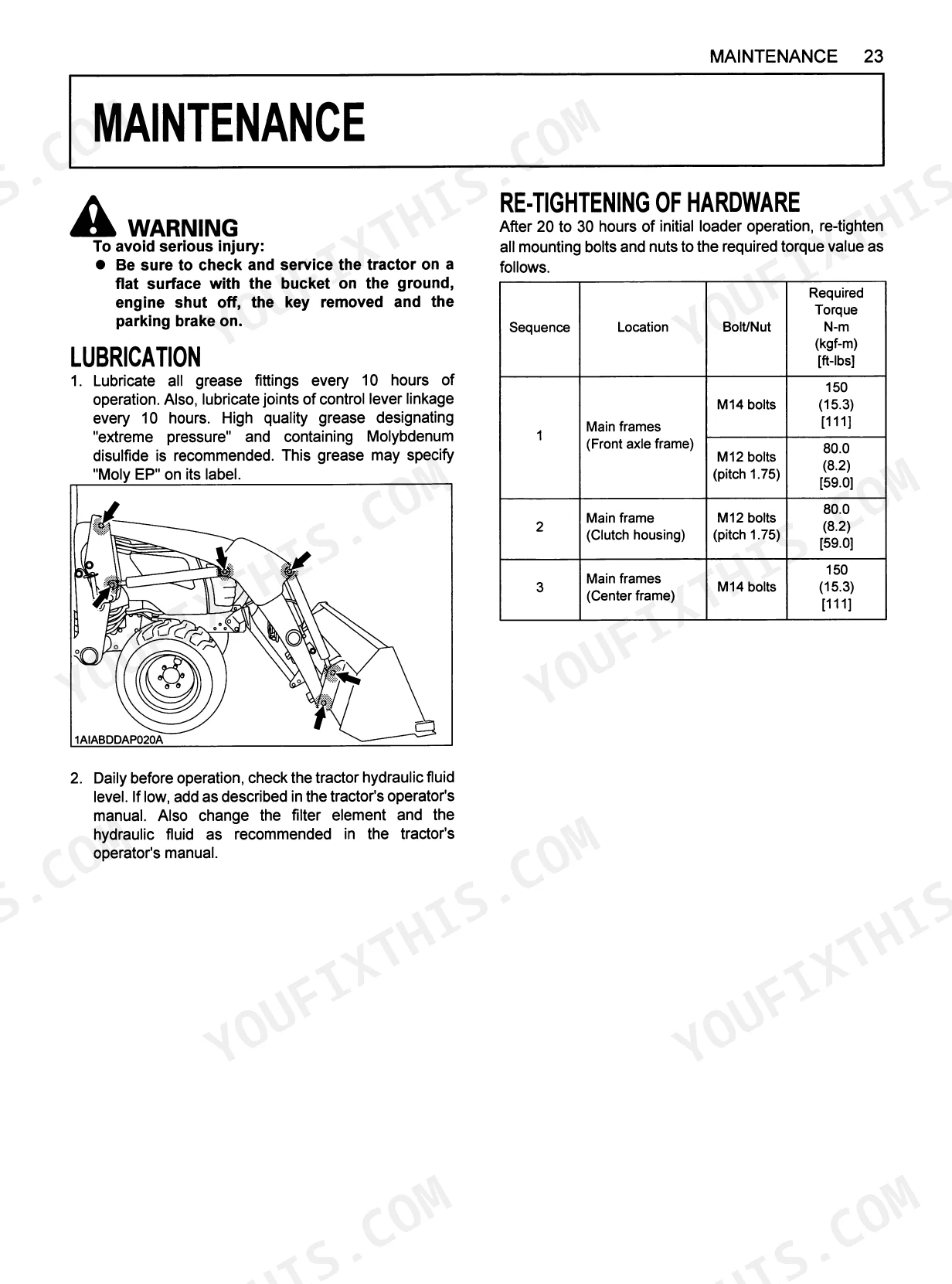
| Servicing of Loader | 11 | Loader specifications, Bucket specifications, Lubrication, Transmission fluid, Removing air from the hydraulic system, Re-tightening of hardware |
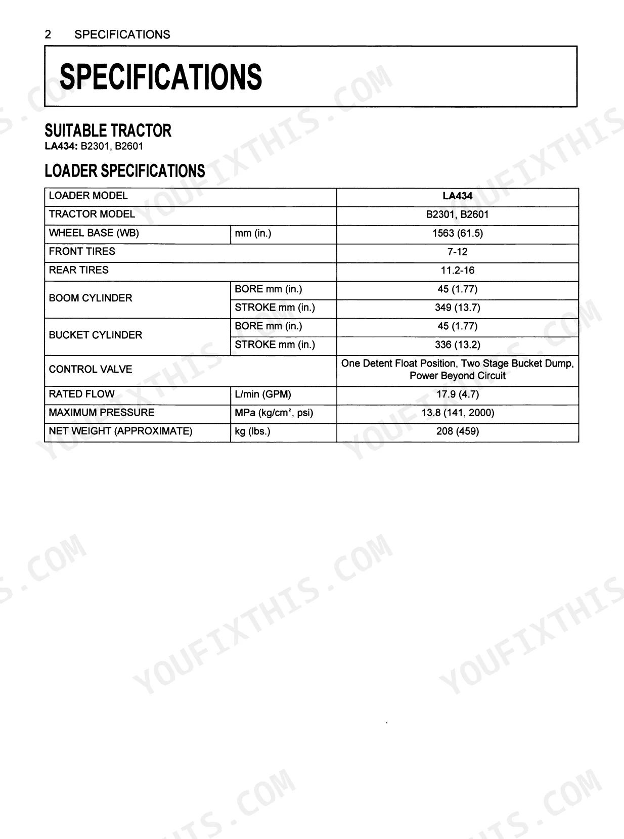
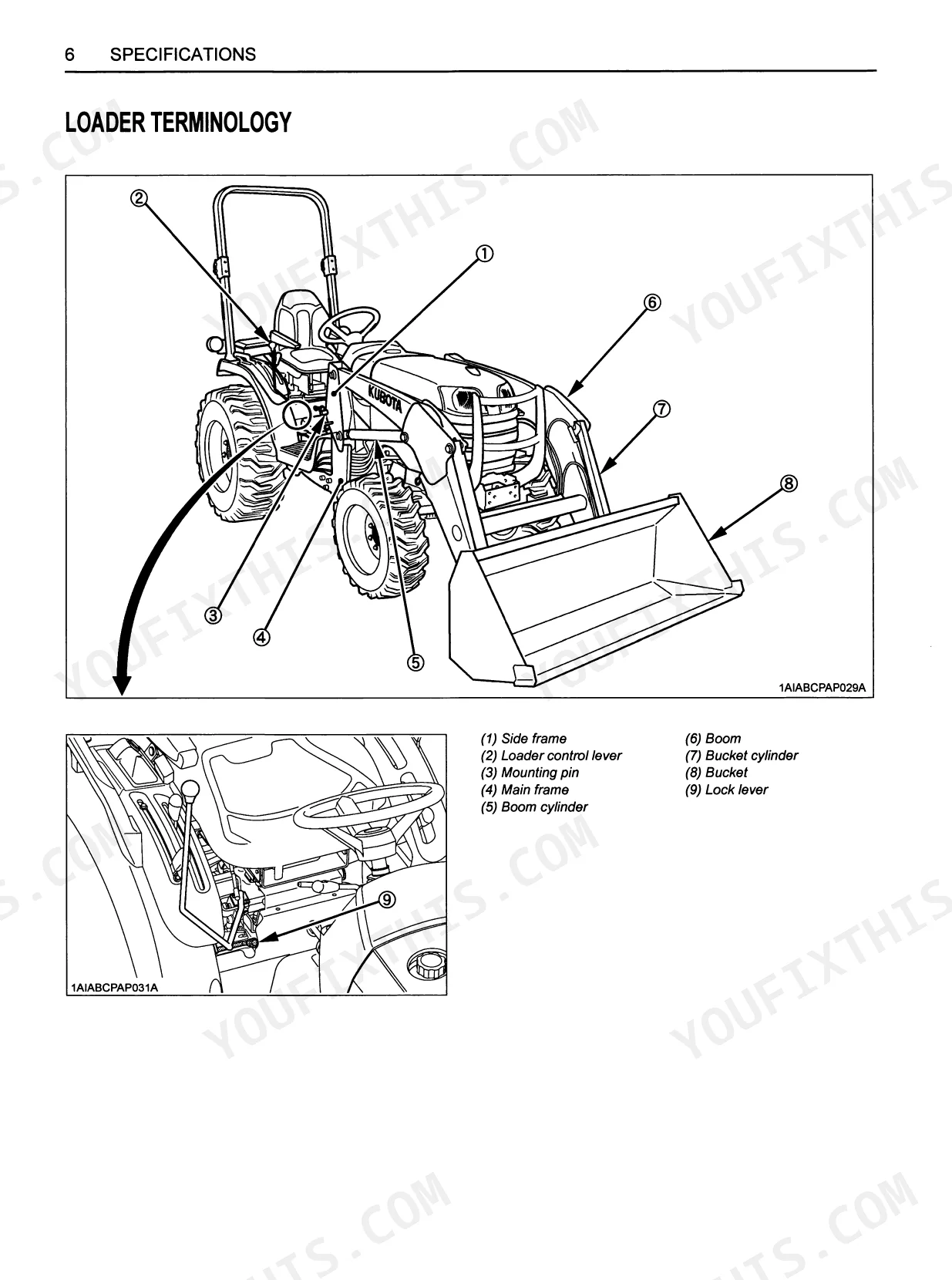
| Specifications | 12-16 | Suitable Tractor, Loader Specifications, Bucket Specifications, Dimensional Specifications, Operational Specifications, Loader Terminology |
| Pre-Operation Check | 17-20 | Lubrication, Transmission Fluid, Rear Ballast, Tire Inflation, Test Operation, Removing Air From The Hydraulic System |
| Operating the Loader | 21-32 | Filling The Bucket, Lifting The Load, Carrying The Load, Dumping The Bucket, Lowering The Bucket, Operating With Float Control, Loading From A Bank, Peeling And Scraping |
| Maintenance | 33-36 | Lubrication, Re-Tightening Of Hardware, Daily Checks, Every 50 Hours (Checking Main Frame Bolt And Nut Torque) |
| Removing the Loader | 37-38 | Stands, Spring pins, Mounting pins, Loader main frame, Hydraulic control lever, Quick couplers |
| Storing the Loader | 39 | Store The Loader In A Clean Dry Place, Make Sure The Loader Is Properly Supported, Attach The Protective Plugs And Caps To The Couplers To Protect Them From Dust |
| Reinstalling the Loader | 40-44 | Loader side frames, Main frames, Hydraulic control lever, Hoses, Couplers, Mounting pins |
Quick Reference Specifications
| Specification | Value | Page |
|---|---|---|
| Main frames (Front axle frame) M14 bolts torque | 150 N-m (15.3 kgf-m, 110 ft-lbs) | p. 35 |
| Main frames (Front axle frame) M12 bolts (pitch 1.75) torque | 80.0 N-m (8.2 kgf-m, 59.0 ft-lbs) | p. 35 |
| Metric cap screws M6 torque | 9.8 to 11.2 N-m (1.0 to 1.1 kgf-m, 7.2 to 8.3 ft-lbs) | p. 36 |
| Metric cap screws M8 torque | 23.6 to 27.4 N-m (2.4 to 2.8 kgf-m, 17.4 to 20.2 ft-lbs) | p. 36 |
| Loader Model | LA434 | p. 12 |
| Wheel Base (WB) | 1563 mm | p. 12 |
| Maximum Hydraulic Pressure | 13.8 MPa (2000 psi) | p. 12 |
| Loader Net Weight (Approximate) | 208 kg (459 lbs.) | p. 12 |
| Max. Lift Height (to bucket pivot pin) | 1995 mm (78.5 in.) | p. 13 |
| Max. Dump Angle | 40 deg. | p. 13 |
| Raising Time | 3.7 sec. | p. 14 |
| Pallet Fork Rated Capacity (LA434) | 177 kg (390 lbs.) | p. 31 |
Kubota LA434 Common Problems This Manual Covers
Kubota LA434 loader feels loose or shifts on mounts when lifting heavy loads p. 35
Inspect all mounting hardware and retighten daily to prevent shifting. Torque the main frame M14 bolts to 150 N-m (110 ft-lbs) using the specifications on page 35. Verify the locking levers and pins are fully engaged to secure the frame before lifting.
Manual Section: Loose HardwareBoom or bucket moves erratically or raises slowly with poor hydraulic response p. 19
Verify the transmission fluid level and check for air in the hydraulic system. If the boom raising time exceeds 3.7 seconds, purge air from the cylinders. Follow the bleeding procedure on page 19 to restore smooth bucket and loader control.
Manual Section: Air in Hydraulic SystemHydraulic fluid leaking visibly around loader hoses, fittings, or main lift cylinders p. 6
Examine all loader hoses and connections for visible wear or damage daily. Verify maximum hydraulic pressure remains under 13.8 MPa (2000 psi) during operation. Review the safety instructions on page 6 before tightening loose fittings to prevent high-pressure fluid injection injuries.
Manual Section: Hydraulic LeaksPallet forks feel unstable or rear tractor wheels lift off the ground p. 31
Measure rear tire inflation and adjust the pressure to 270 kPa (40 psi) to maintain stability. Verify your load does not exceed the pallet fork rated capacity of 177 kg (390 lbs). Check page 31 for safe attachment operating instructions.
Manual Section: Operating the LoaderFrequently Asked Questions
How do I reset the Kubota LA434 loader hydraulic system?
To remove air from the hydraulic system, repeat raising and lowering the boom and bucket operations until all the air is removed and the system responds properly. It is important not to move the control lever into the float position when the bucket is off the ground during this process.
What are the torque specs for the Kubota LA434 mounting bolts?
For the main frames (Front axle frame), M14 bolts require a tightening torque of 150 N-m (15.3 kgf-m, 111 ft-lbs). M12 bolts (pitch 1.75) on the main frame (Clutch housing) and main frames (Center frame) require 80.0 N-m (8.2 kgf-m, 59.0 ft-lbs) and 150 N-m (15.3 kgf-m, 111 ft-lbs) respectively. These bolts should be re-tightened after 20 to 30 hours of initial loader operation.
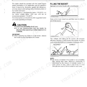
How do I level or adjust a Kubota LA434 front loader bucket?
To level the bucket during operation, approach and enter the pile with a level bucket. When operating on hard surfaces, keep the bucket level and put the lift control in the float position to permit the bucket to float on the working surfaces. After reinstalling the loader, lower the boom and level the bucket.
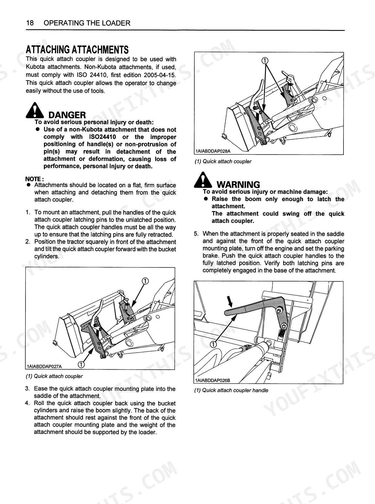
How do I remove and install a Kubota LA434 quick-attach loader?
To remove the loader, first raise the boom to rotate the stands, stop the engine, remove spring pins, and slide/rotate stands into alignment. Then, start the engine, dump the bucket approximately 20 degrees, and lower the boom to slightly raise the front wheels. After stopping the engine and removing mounting pins, start the engine again and slowly move the hydraulic control lever to rollback position to raise the loader side frames out of the main frames. Disconnect the 4 hoses with quick couplers, place protective caps, and back the tractor away. Reinstallation is the reverse process, ensuring the side frames engage the main frames and connecting hoses by color marks.
How quickly can I access this Kubota LA434 manual after buying?
A 44-page Operator Manual in searchable PDF format, available the moment you complete checkout. View on computer, tablet, or phone — no shipping wait.
Are there any print restrictions on this Kubota LA434 manual?
None at all — the PDF is DRM-free. Print whatever sections you need to take out to the shop. Standard letter or A4 paper works.
Document Quality
This document is a scanned PDF, not a native digital file. You can search and copy the full text, as an OCR layer has been applied, making the text crisp and easy to read. Diagrams and illustrations are raster images, but their labels are clear and legible. All pages are clean with no noticeable scan artifacts, stains, marks, or skewed content. There are no blank or filler pages in this manual.


Reviews
There are no reviews yet.