


Filling buckets, loading from a bank, backfilling. The factory Kubota LA535 operator manual walks through the technique for each across its 59 pages, then backs it with the checks that keep the loader running. The first six pages handle safety, including 2-lever and Euro quick-coupler precautions. Next comes the pre-operation checklist: transmission fluid, rear ballast tables, and tire inflation targets. Service intervals are laid out plainly, with daily checks and a re-torque of all mounting hardware after the first 20 to 30 hours of use. Front tires run 170 kPa (24 psi); the hydraulic system tops out at 16.6 MPa (2408 psi). Get the factory answer on the first try, bookmarked by section, keyword-searchable, and readable on your phone right at the machine.
What's Inside This Kubota LA535 Operator Manual
| System | Pages | Key Topics |
|---|---|---|
| Safe Operation | 7-12 | Precautions Before Operating The Loader (2-Lever Quick Coupler, Euro Quick Coupler), Precautions After Operating The Loader, Safety Labels, Care For Safety Labels |
| Servicing of the Loader | 13 | Dealer Service, Kubota Loader (Model, Serial Number, Date of Purchase, Name of Dealer, To Be Filled in by the Purchaser) |
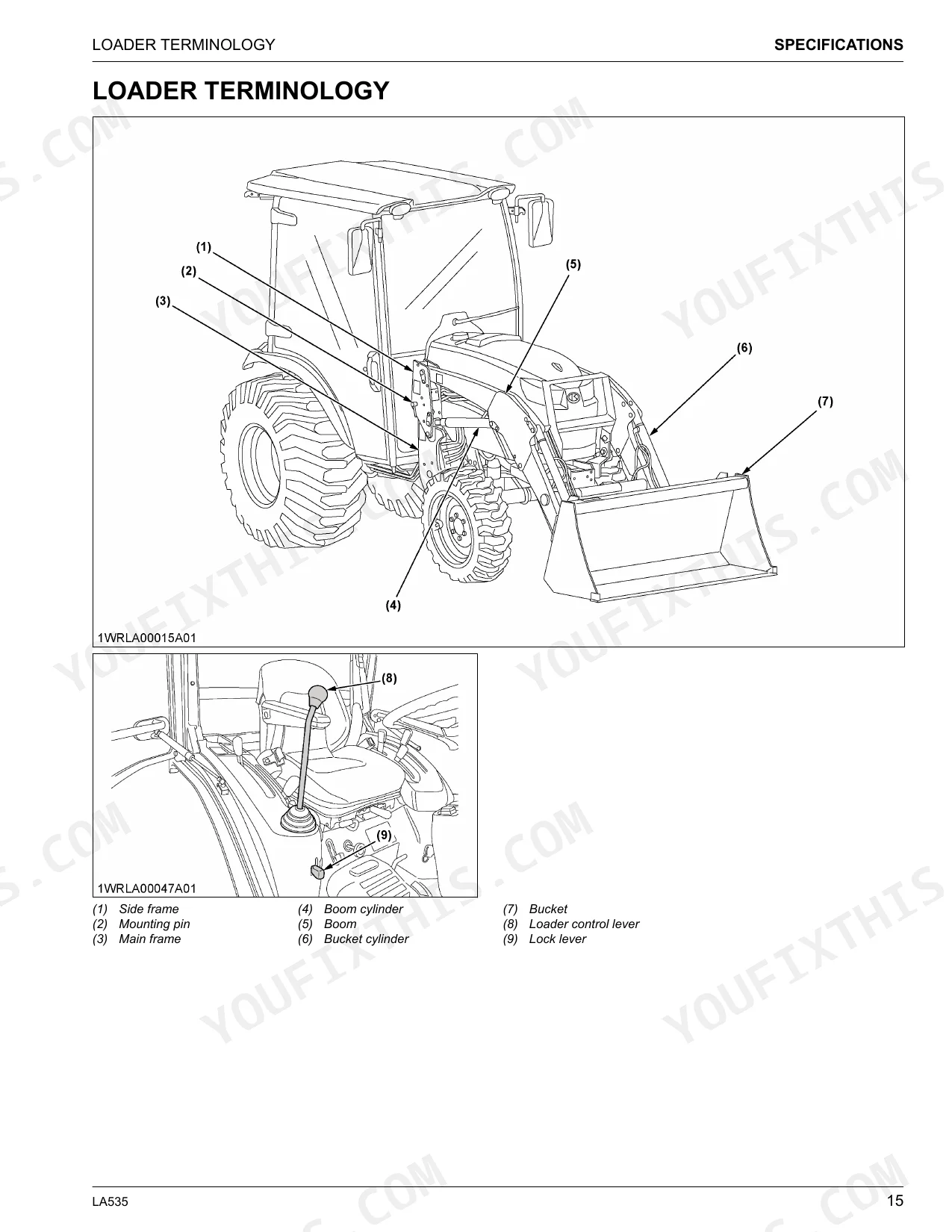
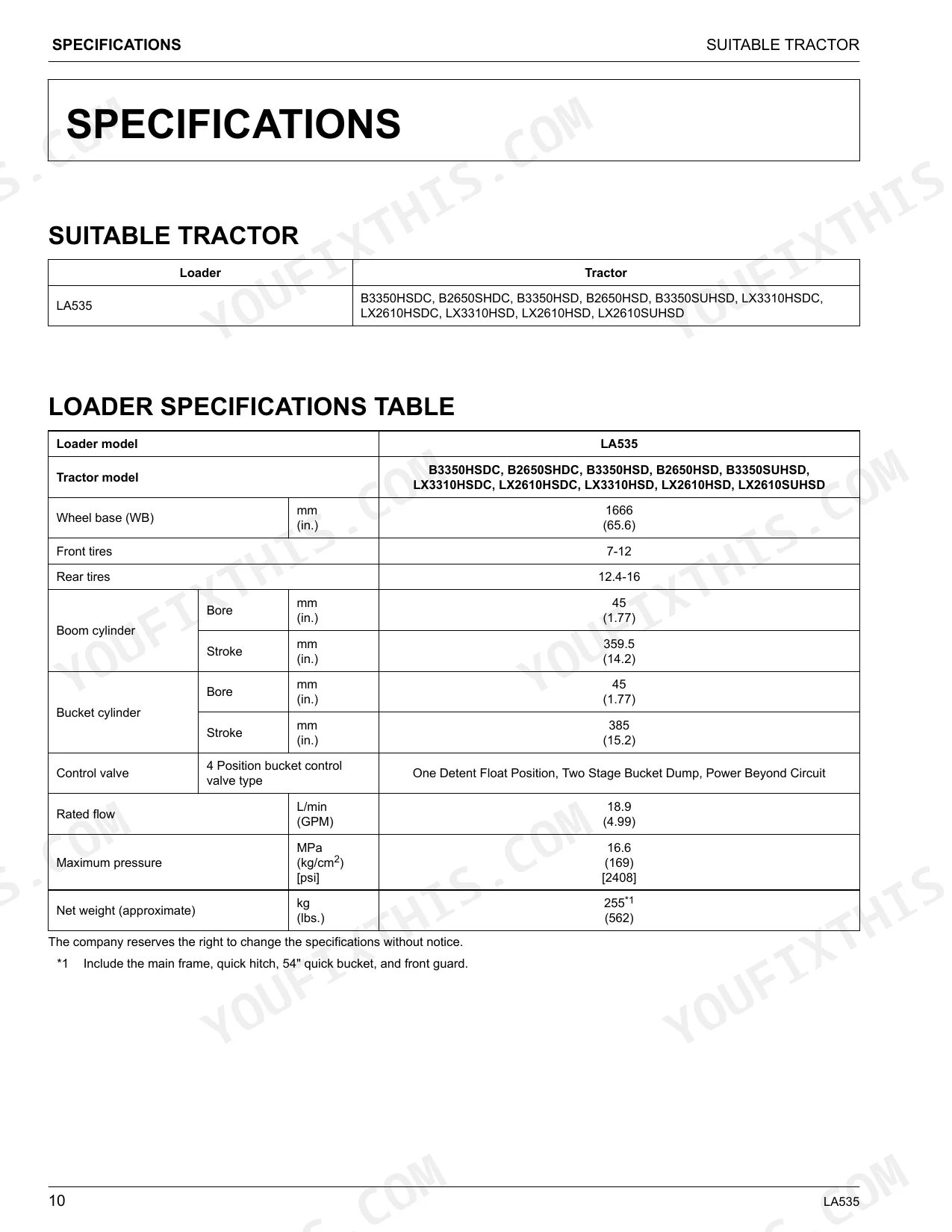
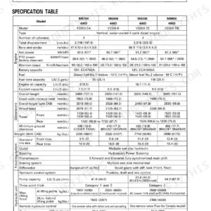
| Specifications | 14-19 | Suitable Tractor, Loader Specifications Table, Bucket Specifications Table, Dimensional Specifications, Operational Specifications, Loader Terminology |
| Pre-Operation Check | 20-25 | Lubrication Before Operating the Loader, Checking the Transmission Fluid, Setting the Tread, Weight of the Implements as the Rear Ballast, Liquid Ballast in the Rear Tires |
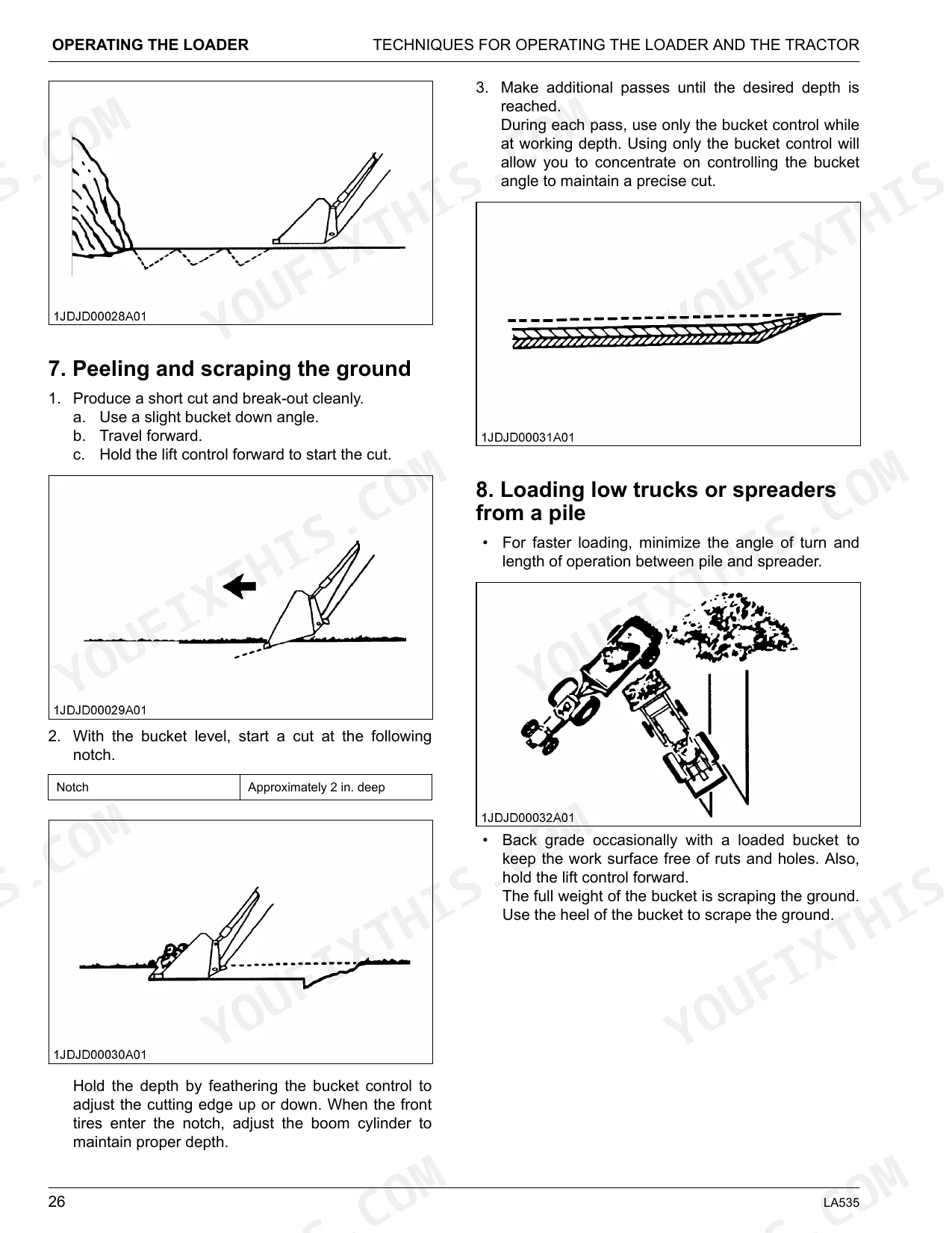
| Operating the Loader | 26-37 | Operation of the Loader, Techniques for Operating the Loader and the Tractor, Filling the Bucket, Dumping and Lowering the Bucket, Loading From a Bank |
| Maintenance | 38-40 | Lubricating the Loader, Service Every 20 Hours to 30 Hours, Re-Tightening of Hardwares of the Loader, Re-Tightening of Hardwares of Mechanical Self Leveling [If Equipped] |
| Removing the Loader | 41-44 | How to Remove the Loader (Removing Non Swift-Tach Loader, Lift the Weight Off the Front Wheels with the Bucket, Stop the Engine, Remove the Mounting Pins From the Loader Main Frame and Store Them on Boom, Start the Engine and Run at Idle, Slowly Release All Hydraulic Pressure by Moving the Hydraulic Control Lever in All Directions, Disconnect the 4 Hoses with Quick Couplers at the Control Valve, Hook the Hoses on the Side Frame and Attach the Protective Plugs to Their Respective Couplers as Shown Below, Confirm the Following Points, Place the Protective Caps on the Quick Coupler Ends, Start the Engine and Slowly Back the Tractor Away From the Loader) |
| Storage of the Loader | 45 | Storing the Loader (Store the Loader in a Clean, Dry Place, Make Sure That the Loader Is Properly Supported, Check the Hydraulic Hoses and Connections, Repair or Replace Any Worn, Damaged, or Missing Parts, Lubricate the Loader as Described on Lubricating the Loader on Page 34, Apply a Coat of Grease to All Exposed Cylinder Rods to Prevent Rust, Repaint Worn or Scratched Parts) |
| Reinstalling the Loader | 46-57 | How to Reinstall the Loader (Reinstalling Non Swift-Tach Loader, Start the Engine and Run at Idle, Slowly Move the Hydraulic Control Lever to Dump Position to Lower the Side Frames Into the Main Frames and Engage the Bosses of the Main Frames to the Guide Bosses of the Main Frames, Stop the Engine, Reinstall the Mounting Pins and Secure Them with the Locking Rods, Start the Engine, Raise the Boom Until the Stand Can Be Rotated, Store the Stands to Their Original Positions and Secure Them with the Spring Pins as Shown, Lower the Boom and Level the Bucket, Reinstalling Swift-Tach Loader [If Equipped], Carefully Drive the Tractor Between the Side Frames of the Loader as Shown in the Following Figures, Set the Parking Brake and Unfasten the Seat Belt, Remove the Protective Caps From the Tractor Quick Coupler, Take Off the Dust Cap, Fold the Dust Cap, Leave Dust Cap Hanging, Align the Quick Coupler with the Bottom Side Quick Coupler on Tractor and Rotate the Lever Down Until the Quick Coupler Locks, Make Sure That the Mounting Levers of Both Sides Are in the Lock Position as Shown in the Follow Figures, Fasten the Seat Belt and Start the Engine, Slowly Operate the Loader Control Lever to Roll the Bucket Back and Extend the Boom Cylinders Until the Left and Right Guide Bosses of Side Frames Contact the Main Frames, Slowly Operate the Loader Control Lever to the Dump Position to Lower the Side Frames Into the Main Frames, and Engage the Left and Right Guide Bosses of the Side Frames to the Saddle Bracket of the Main Frames, as Shown in the Following Figure, Make Sure That the Left and Right Bosses of the Side Frames Are Engaged by the Saddle Bracket of the Main Frames, Slowly Operate the Loader Control Lever to the Down Position to Lift the Front Wheels Slightly with the Loader Until the Mount Hooks Are Completely Mounted on the Main Frame as Shown in the Following Figure, Make Sure That the Stand Lever Is at Its Low Position as Shown in the Following Figure, Slowly Dump the Bucket Until the Stands Are in the Stowed Position, Using the Stand Lever Lock the Stands in the Stowed Position as Shown Below, Verify LH/RH Stand Hooks Are Engaged Properly as Shown Below) |
Quick Reference Specifications
| Specification | Value | Page |
|---|---|---|
| Loader mounting bolts torque | 124 to 147 N·m (12.6 to 15.0 kgf·m) (91.5 to 108.4 lbf·ft) for bolts (2) (4) and main frame connector bolt (2); 80.0 to 90.0 N·m (8.2 to 9.2 kgf·m) (59.0 to 66.4 lbf·ft) for bolt (3); 260 to 304 N·m (26.5 to 31.0 kgf·m) (192 to 224 lbf·ft) for Mechanical self leveling bolts (1) (2) (3) | p. 38 |
| Rated flow | 18.9 L/min (4.99 GPM) | p. 14 |
| Maximum pressure | 16.6 MPa (2408 psi) | p. 14 |
| Net weight (approximate) | 255 kg (562 lbs.) | p. 14 |
| Front tire inflation pressure (7-12, 4PR) | 170 kPa (24 psi) | p. 19 |
| Rear tire inflation pressure (12.4-16, 4PR) | 110 kPa (16 psi) | p. 19 |
| Raising time | 3.6 sec. | p. 17 |
| Lowering time | 2.3 sec. | p. 17 |
| Main frame bolt torque (2)(4) | 124 to 147 N·m (91.5 to 108.4 lbf·ft) | p. 34 |
| Mechanical self leveling bolt torque (1)(2)(3) | 260 to 304 N·m (192 to 224 lbf·ft) | p. 35 |
| Stand lever roller clearance | 1 to 2 mm (0.04 to 0.08 in.) | p. 53 |
| M10 Tightening torque (stand lever rod) | 39.2 to 45.1 N·m (28.9 to 33.2 lbf·ft) | p. 53 |
Kubota LA535 Common Problems This Manual Covers
Kubota LA535 bucket won't curl or boom won't lift after moving the hydraulic control lever p. 24
Check the troubleshooting steps on page 24. Make sure the control lever moves freely in all four positions and the tractor hydraulic circuit is live. If the boom still won't move, purge air by cycling it fully up and down three times, then curling and dumping the bucket all the way (page 24). System pressure is rated at 16.6 MPa (2408 psi) (page 14).
Manual Section: Pre-Operation CheckBoom or bucket movement feels spongy or erratic when operating the loader p. 24
Purge air from the hydraulic lines before looking further (page 24). With the engine at idle, cycle the boom from full down to fully raised three times and run the bucket all the way in and out. Normal boom raising time is 3.6 seconds (page 17); sluggish or erratic movement that survives the purge usually means a low fluid level. Check transmission fluid per page 20.
Manual Section: Pre-Operation CheckHydraulic hoses showing wet spots, cracks, or rubbing marks on the boom or frame p. 7
Inspect all hoses and connections before each use, following the safety check on page 7. Run a clean rag along every hose from the quick-coupler connections to the control valve, feeling for cuts, abrasion, or damp spots. At up to 16.6 MPa (2408 psi) (page 14), a worn hose is a serious hazard. Replace any damaged hose before operating.
Manual Section: Safe OperationLoader stand won't lock in the stowed position after reconnecting to the tractor p. 51
Confirm the stand lever is in the low position before stowing (page 51), and that both the left and right stand hooks are fully seated on the saddle brackets (page 51). If the lever binds, set roller clearance to 1 to 2 mm (0.04 to 0.08 in.) on page 53, then torque the M10 rod lock nut to 39.2 to 45.1 N·m (28.9 to 33.2 lbf·ft).
Manual Section: Reinstalling the LoaderMain frame feels loose or shifts when curling and lifting heavy bucket loads p. 38
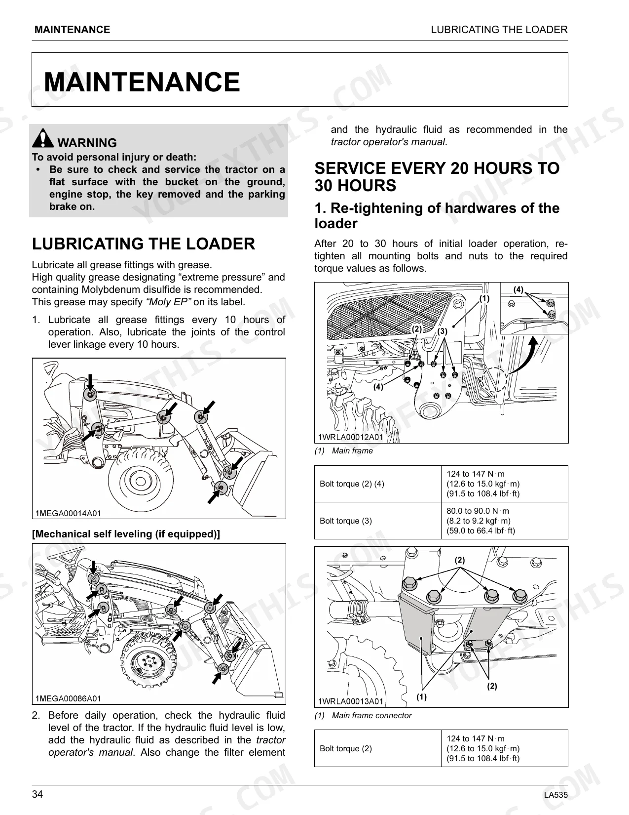
Stop work and re-torque all main frame mounting hardware on the schedule on page 38. Bring main frame bolts (2) and (4) to 124 to 147 N·m (91.5 to 108.4 lbf·ft) and bolt (3) to 80.0 to 90.0 N·m (59.0 to 66.4 lbf·ft) (page 38). If the loader has mechanical self-leveling, also torque bolts (1)(2)(3) to 260 to 304 N·m (192 to 224 lbf·ft) per page 39.
Manual Section: MaintenanceFront wheels lift or tractor tips during bucket lift cycles at normal operating height p. 22
Set front tire pressure to 170 kPa (24 psi) for 7-12 4PR tires as shown on page 23, and confirm rear ballast is in place before loading (page 22). Review the ballast requirements on page 22: running the loader without enough rear counterweight shifts the center of gravity forward, cutting steering response and ground contact at the rear tires.
Manual Section: Pre-Operation CheckFrequently Asked Questions
What are the torque specs for Kubota LA535 loader mounting bolts and hydraulic fittings?
Re-tighten all mounting bolts and nuts after the first 20 to 30 hours of operation. On the main frame, torque bolts (2) and (4) to 124 to 147 N·m (91.5 to 108.4 lbf·ft) and bolt (3) to 80.0 to 90.0 N·m (59.0 to 66.4 lbf·ft). The main frame connector bolt (2) also takes 124 to 147 N·m (91.5 to 108.4 lbf·ft).
How do I bleed the hydraulic system on a Kubota LA535?
To bleed the hydraulic system, raise and lower the boom and dump and roll back the bucket repeatedly until all the air is out and the system responds properly. Do not move the loader control lever into the float position while the bucket is off the ground.
How do I remove and reinstall a Kubota LA535 front loader?
To remove the loader, follow the "HOW TO REMOVE THE LOADER" section starting on page 37. For reinstallation, see "HOW TO REINSTALL THE LOADER" starting on page 42. Make sure an approved bucket is attached before removal and that the ground is flat and hard.
how to reset Kubota LA535 loader
The manual has no specific procedure for "resetting" the LA535 after a fault or service advisory. It does explain how to purge air from the hydraulic system by cycling the boom and bucket, and how to re-tighten the mounting bolts after initial operation.
Kubota LA535 torque specs for loader mounting bolts
At the 20-to-30-hour mark on a new loader, main frame bolts (2) and (4) get 124 to 147 N·m (91.5 to 108.4 lbf·ft) and bolt (3) gets 80.0 to 90.0 N·m (59.0 to 66.4 lbf·ft). The main frame connector bolt (2) takes the same 124 to 147 N·m (91.5 to 108.4 lbf·ft) as the frame bolts.
How quickly can I access this Kubota LA535 manual after buying?
Immediate download of the complete 59-page searchable operator manual. Open it on any device: a laptop at your desk or a phone in the field.
Are there any print restrictions on this Kubota LA535 manual?
Yes. Print as many copies as you want, with no restrictions. Plenty of mechanics print just the section they need and take it to the shop floor.
Document Quality
This document is an OCR'd scan, allowing you to search and copy the full text. The text quality is crisp and easy to read throughout the manual. Diagrams and illustrations are clear raster images, with all labels perfectly readable. Pages are clean with no scan artifacts or skewed content, though page 4 is intentionally blank. Overall, the document is well-presented and functional for reference.


Reviews
There are no reviews yet.