


All 398 pages of this Kubota M7040DT-SU Workshop Manual (OEM #9Y111-04573) cover a single machine: the M7040DT-SU tractor, with factory-accurate data spanning the full 2001-2014 production run. You get wiring diagrams for the starting and charging systems, lighting, and meter panel, plus hydraulic schematics that trace the complete three-point hydraulic circuit. Inside: 50 pages of exploded views, 100 pages of step-by-step procedures across engine, clutch, transmission, rear axle, brakes, front axle, and steering, plus troubleshooting charts for every major system. Fill your transmission case to 44.0 L and top off the 11.0 L engine sump; cylinder head screws torque to 186-196 N-m, connecting rods to 68.6-73.5 N-m. No more chasing specs across a dozen forum threads. Bookmarked PDF, keyword-searchable; pull it up on your tablet, walk to the tractor, and get the right number on the first try.
What's Inside This Kubota M7040DT-SU Manual
| System | Pages | Key Topics |
|---|---|---|
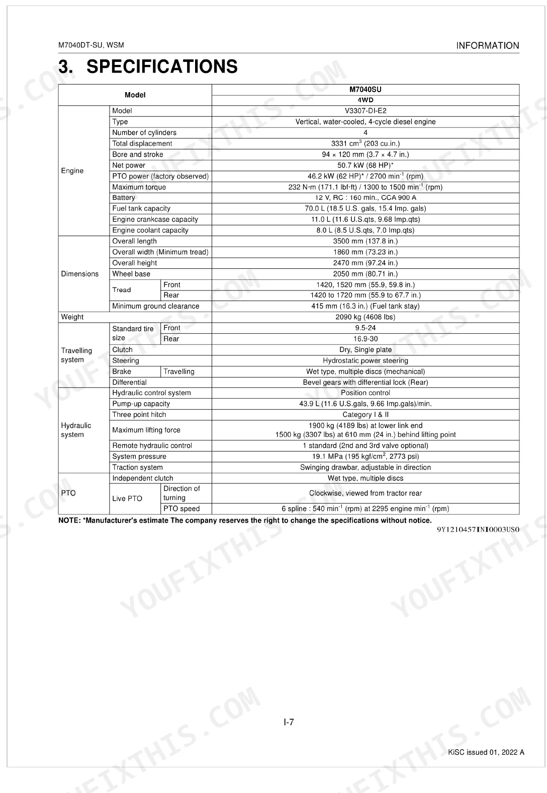
| Information | 4-14 | Safety First, Safety Decals, Specifications, Traveling Speeds, Dimensions |
| General | 15-95 | Tractor Identification (Model Name and Serial Numbers, Cylinder Number) |
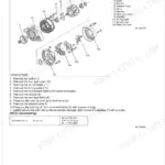
| Engine | 96-183 | Feature |
| Clutch | 184-214 | Travelling Clutch (Features, Linkage), PTO Clutch (Structure, Oil Flow, Valve), Troubleshooting (Travelling Clutch, PTO Clutch) |
| Transmission | 215-255 | Structure, Traveling System (Main Gear Shift Section, Shuttle Shift Section, Hi-Range Shift Section, Shift Linkage Mechanism, Four Wheel Drive Section), Pto System |
| Rear Axle | 256-268 | Features, Troubleshooting, Servicing Specifications, Tightening Torques |
| Brakes | 269-280 | Structure, Troubleshooting, Servicing Specifications, Checking And Adjusting (Brake Pedal Free Travel), Disassembling And Assembling (Brake: Pedal And Linkage, Case) |
| Front Axle | 281-302 | Structure (Wheel Drive), Troubleshooting, Servicing Specifications, Tightening Torques |
| Steering | 303-320 | Structure (Steering Mechanism), Troubleshooting, Servicing Specifications (Hydraulic Pump, Steering Controller, Steering Cylinder), Tightening Torques |
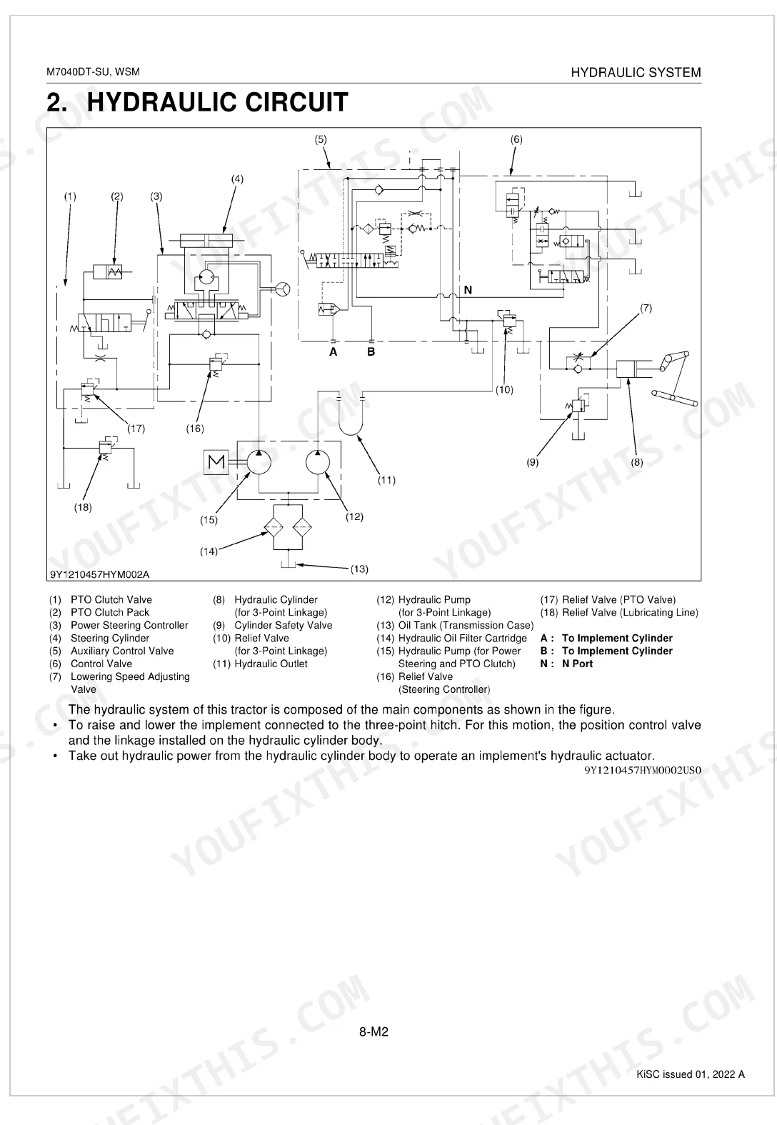
| Hydraulic System | 321-347 | Structure, Hydraulic Circuit, Hydraulic Circuit For Three Point Hydraulic System, Hydraulic Block, Linkage Mechanism, Troubleshooting, Servicing Specifications, Tightening Torques |
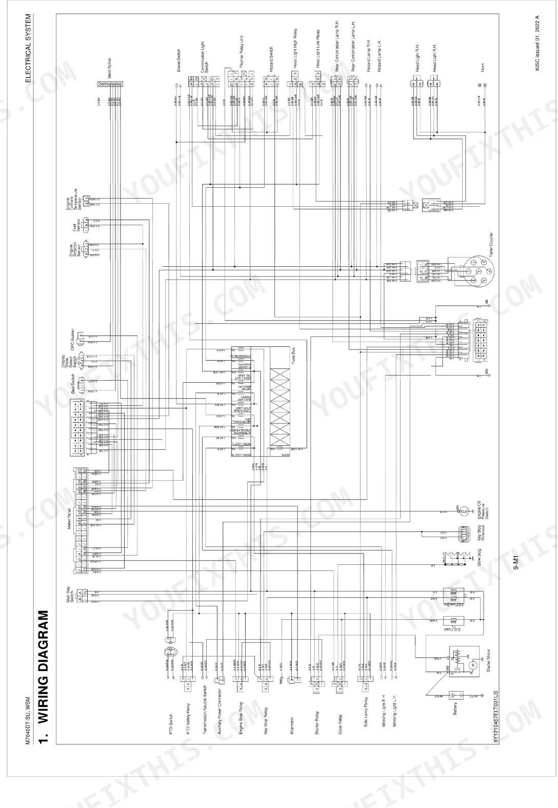
| Electrical System | 348-398 | Wiring Diagram, Electrical Circuit Detailed Chart (Starting System and Charging System, Lighting System, Meter Panel) |
Quick Reference Specifications
| Specification | Value | Page |
|---|---|---|
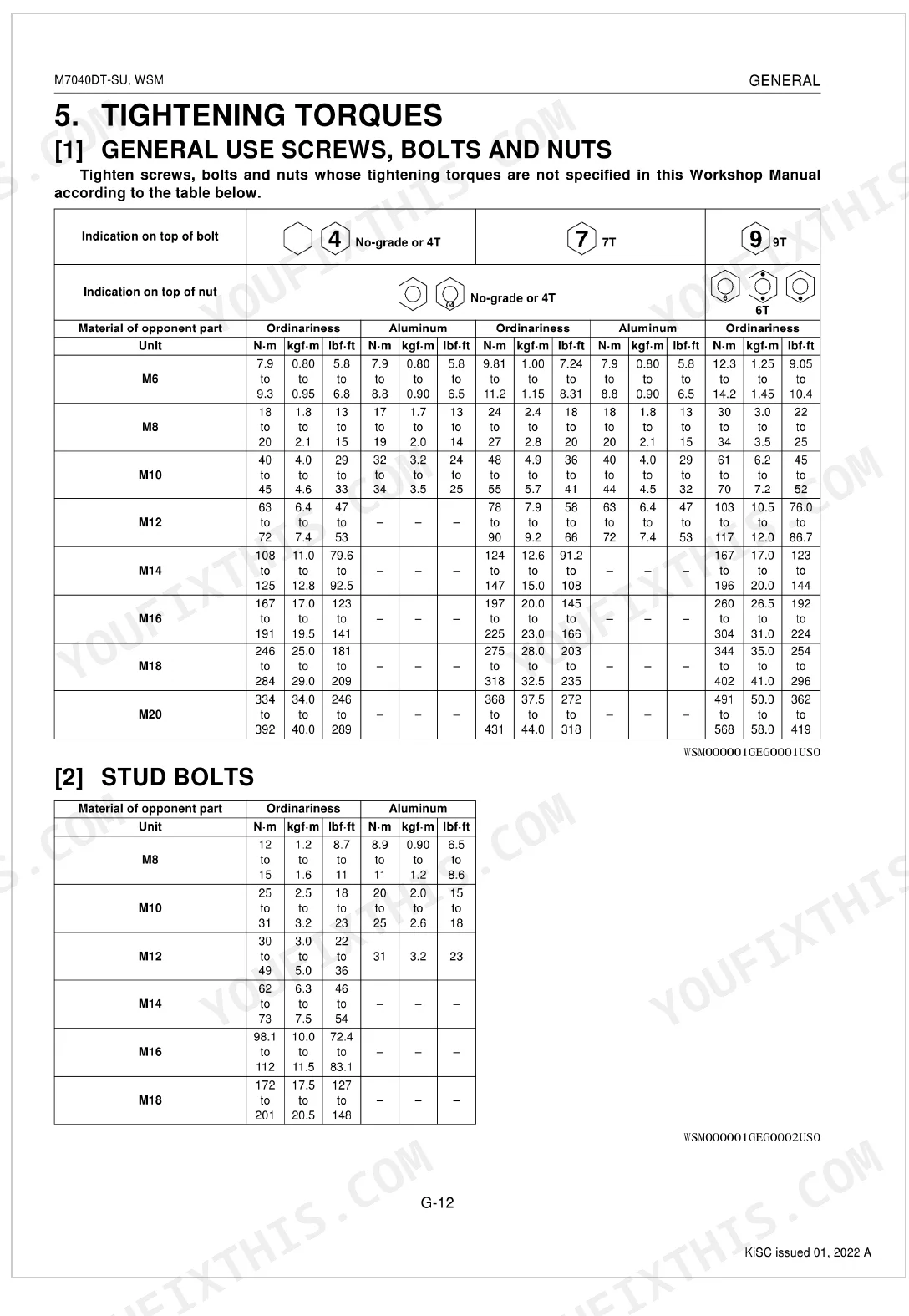
| Cylinder head mounting screw torque (Bolt head with stamp "10") | 186 to 196 N-m (19.0 to 20.0 kgf-m, 137 to 145 lbf·ft) | p. 28 |
| Connecting rod screw torque | 68.6 to 73.5 N-m (7.0 to 7.5 kgf-m, 50.6 to 54.2 lbf·ft) | p. 28 |
| Engine Oil Capacity | 11.0 L | p. 26 |
| Transmission Case Capacity | 44.0 L | p. 26 |
| Front Differential Gear Case Capacity | 6.6 L | p. 26 |
| Coolant Capacity | 8.0 L | p. 26 |
| Cylinder Head Mounting Screw Torque | 186 to 196 N-m | p. 122 |
| Engine Oil Pressure (At Idle Speed) | 49 kPa | p. 120 |
| Alternator Belt Tension (Deflection) | 16 to 17 mm | p. 120 |
| Injection Pressure (1st stage) | 18.63 to 19.61 MPa | p. 121 |
| Piston Ring Gap (Top ring) | 0.25 to 0.40 mm | p. 118 |
| Valve Stem O.D. (Intake and exhaust) | 6.960 to 6.975 mm | p. 116 |
Kubota M7040DT-SU Common Problems This Manual Covers
Kubota M7040DT-SU engine cranks but won't fire in cold weather, glow plug light stays on p. 113
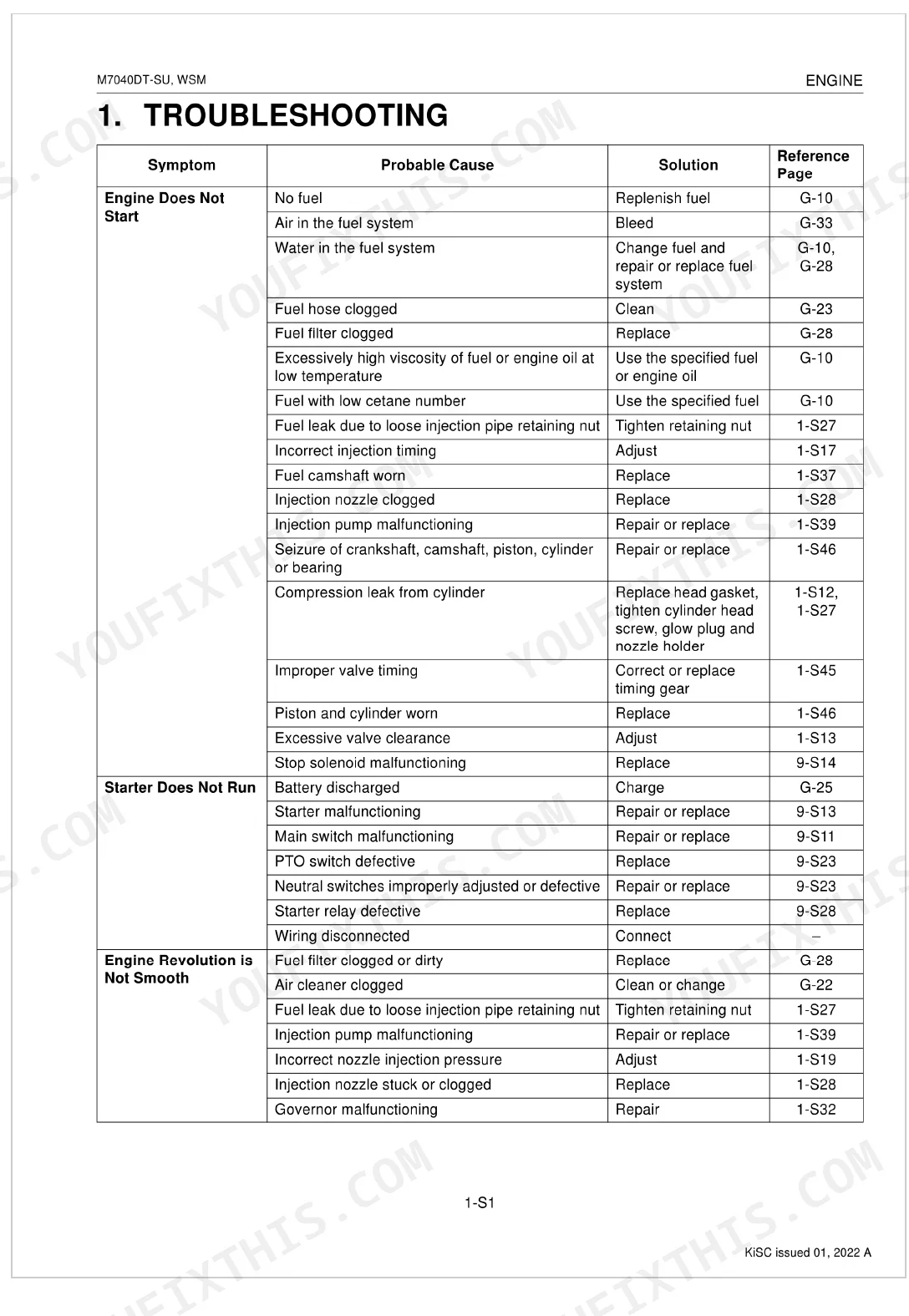
Check the engine troubleshooting chart for a no-start decision tree (page 113). Verify glow plugs heat within 10 seconds of key-on. Test injection pressure at the pump: spec is 18.63 to 19.61 MPa (page 121). If it cranks without firing, replace the fuel filter per the 400-hour interval on page 30 and bleed the fuel lines.
Manual Section: Engine TroubleshootingThree-point hydraulic implement won't rise or stops short of maximum lift height p. 330
Inspect hydraulic fluid level first: the transmission case holds 44.0 L (page 26) and supplies the entire hydraulic circuit. Check the lift arm linkage for bent or seized pivot pins. Work through the hydraulic troubleshooting procedures at page 330, focusing on relief valve pressure and control valve operation. A stuck relief valve is the most common cause of incomplete lift.
Manual Section: Hydraulic System TroubleshootingTransmission gears hard to shift or clash with grinding noise engaging any gear p. 227
Adjust clutch pedal free travel before touching the gearbox: clutch drag is the leading cause of gear clash in this transmission. Check transmission fluid level against the 44.0 L capacity (page 26) and inspect shift linkage rods for bent or worn pivot joints. Work through the transmission troubleshooting steps at page 227 to isolate linkage issues from internal gear problems.
Manual Section: Transmission TroubleshootingSteering wheel requires excessive effort to turn at low speed, front wheels wander p. 307
Check hydraulic fluid level in the transmission case: capacity is 44.0 L (page 26), and the steering circuit pulls from the same reservoir as the hydraulics. Inspect the steering pump and steering cylinder for external leaks. Work through the steering troubleshooting procedures at page 307, paying close attention to relief pressure specs and steering controller condition in the servicing specifications.
Manual Section: Steering TroubleshootingBattery discharges too quickly between uses and starter motor turns over slowly p. 360
Test alternator belt deflection first: spec is 16 to 17 mm (page 120). A loose belt is the single most common cause of chronic discharge on this tractor. Check for parasitic draw with a multimeter in series at the battery negative terminal, disconnecting loads one at a time. Inspect all ground connections at the battery, starter, and frame before condemning the alternator.
Manual Section: Electrical System TroubleshootingBrake pedal pulls to one side or both pedals feel uneven and spongy under load p. 273
Check brake pedal free travel on both sides: unequal adjustment is the most common cause of pulling and uneven braking force. Inspect brake linings for oil contamination from a leaking rear axle seal. Verify the transmission case is filled to 44.0 L (page 26). Work through the brake troubleshooting procedures at page 273 to separate a lining issue from a hydraulic problem.
Manual Section: Brakes TroubleshootingFrequently Asked Questions
What are the recommended service intervals?
Recommended service intervals include checking engine oil every 50 hours and changing it every 200 hours. The air cleaner element should be cleaned every 100 hours and replaced every 1 year. Transmission fluid should be changed every 800 hours, and the cooling system should be flushed every 2 years.
What fluids and capacities does this machine require?
The fuel tank requires 70.0 L (18.5 U.S. gals) of No. 1-D diesel fuel. The engine crankcase requires 11.0 L (11.6 U.S. qts) of API Service Classification CC or CD oil, with specific SAE grades depending on temperature. The transmission case needs 44.0 L (46.5 U.S. qts) of KUBOTA UDT or SUPER UDT fluid.
How to troubleshoot engine won't start?
If the engine does not start, common issues include a blown fuse (replace, page 9-S10), a defective engine stop solenoid (replace, page 9-S14), or a faulty key stop relay (replace, page 9-S30). Additionally, a defective PTO switch or neutral switch can prevent the engine from starting (replace, page 9-S23).
What are the hydraulic system specifications?
The hydraulic pump delivery at rated pressure is 31.1 L/min (8.22 U.S.gals/min). The relief valve setting pressure is 18.2 to 19.1 MPa (185 to 195 kgf/cm²). The cylinder liner bore I.D. is 90.000 to 90.050 mm (3.5433 to 3.5452 in.), and the hydraulic arm shaft O.D. (Right) is 49.950 to 49.975 mm (1.9666 to 1.9675 in.).
What format is this Kubota M7040DT-SU manual in?
This is a 398-page searchable PDF ready for immediate download. Works on any device — pull it up on your phone while you're under the hood. No shipping, no waiting.
Are there any print restrictions on this Kubota M7040DT-SU manual?
No restrictions at all. Print individual pages, full chapters, or the entire manual. The PDF is completely unlocked.
Can I find hydraulic circuit diagrams in this Kubota M7040DT-SU manual?
Yes — complete hydraulic schematics with flow diagrams, valve configurations, and pressure specifications are included.
Document Quality
This document is a native digital PDF, allowing you to easily search and copy all text, which is consistently crisp and clear throughout. Diagrams and illustrations are primarily vector graphics, ensuring they remain sharp and readable even at high zoom levels, with all labels clearly legible. The pages are clean, free from scan artifacts, stains, or skewed content, presenting a professional and easy-to-read manual. There are no notable blank or filler pages, providing a focused and efficient resource.

Reviews
There are no reviews yet.