

Part of the New Holland Repair Manuals.
This is the full factory repair manual for the New Holland T7030, T7040, T7050 and T7060 tractors, the same service information a dealer technician works from. It is organised the way CNH built the tractor: the hydraulic power systems first, then a very large electrical and electronic section, then the engine, powershift transmission, axles, PTO, brakes, cab and the three-point hitch. Roughly a thousand pages are given over to wiring schematics, harness and connector views, and the fault-code tables and diagnostic routines behind them, which is what most T7000 troubleshooting actually comes down to. Every section carries the specifications, tightening torques, pressure test values and step-by-step removal and overhaul procedures.
What's Inside This New Holland T7030, T7040, T7050, T7060 Repair Manual
| System | Pages | Key Topics |
|---|---|---|
| Primary Hydraulic Power System | 25-289 | Main Hydraulic Pump and Load-Sensing Circuit, Closed-Centre Mechanical Remote Valves, Electro-Hydraulic Remote Valves, Charge and Standby Pressure Tests, Flow Control Valve Adjustment |
| Secondary Hydraulic and Hydraulic Command Systems | 297-321 | Secondary Hydraulic Supply, Hydraulic Command Circuits, Power-Beyond Connections, Signal Valve Testing and Removal |
| Pneumatic System | 329-337 | Air Compressor, Trailer Air-Brake Supply, Reservoir and Pressure Regulation |
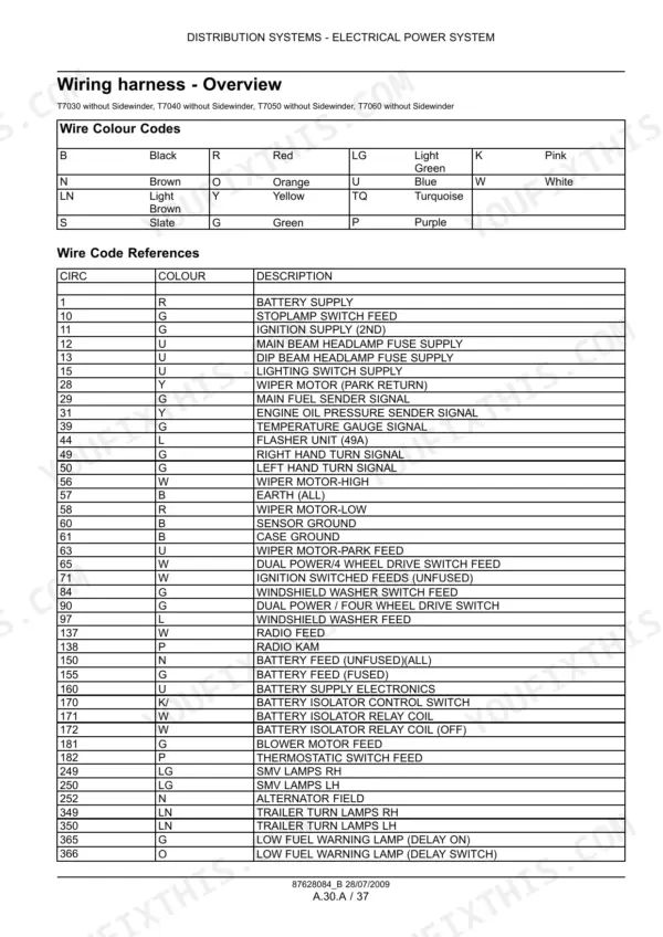
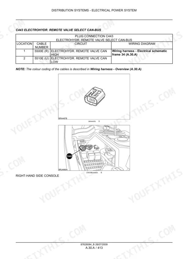
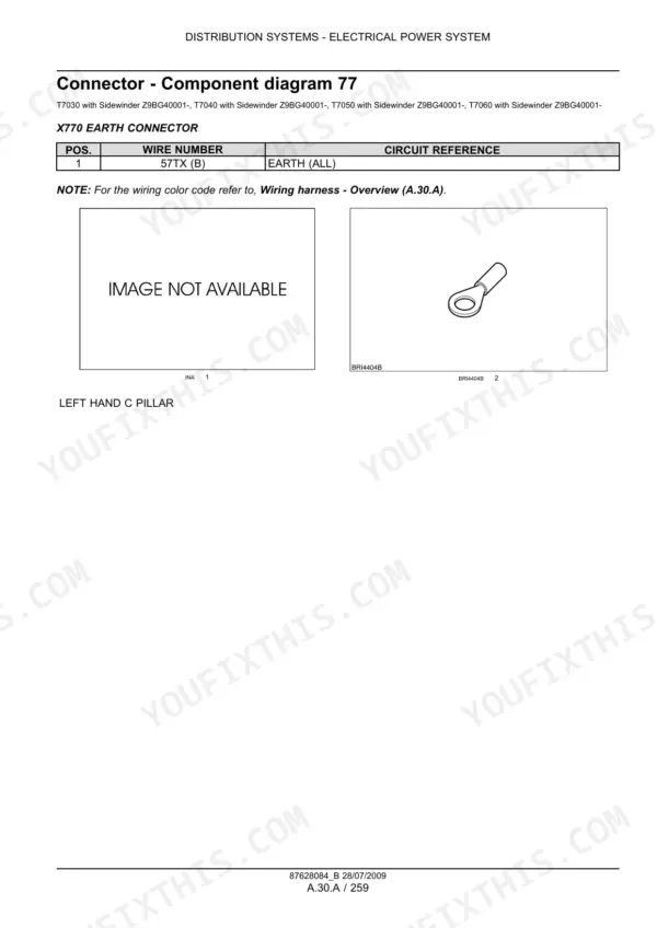
| Electrical Power System and Wiring Diagrams | 345-1313 | Full Wiring Schematics, Harness Routing and Connector Views, Fuses and Relays, Charging and Battery Circuits, Lighting and Instrument Circuits |
| Electronic System and Fault Codes | 1321-1897 | Control Modules and CAN Bus, Sensor and Actuator Data, Fault-Code Tables, Diagnostic Test Procedures, Calibration Routines |
| Engine | 1913-2009 | Cylinder Head and Valve Train, Valve Timing and Tappet Clearance, Rocker and Camshaft Torques, Crankshaft and Pistons, Engine Removal and Refit |
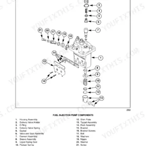
| Fuel and Injection System | 2017-2041 | High-Pressure Injection Pump, Injectors, Fuel Filters and Lift Pump, Bleeding and Injection Timing Checks |
| Air Intake and Exhaust Systems | 2049-2065 | Air Cleaner and Intake Ducting, Turbocharger, Exhaust Manifold and Silencer |
| Engine Coolant System | 2073-2105 | Radiator and Expansion Tank, Water Pump and Thermostat, Cooling Fan Drive, Coolant Capacity and Pressure Testing |
| Lubrication and Starting Systems | 2113-2129 | Oil Pump and Pressure Relief, Oil Filter and Cooler, Starter Motor, Glow Plug and Grid Heater Circuits |
| Powershift Transmission and Additional Reducers | 2137-2257 | Powershift Clutch Packs and Control Valves, Range Gears, Creeper Unit, Overdrive Unit, Clutch Pressure Testing |
| Power Take-Off, Rear and Front | 2265-2353 | Mechanical Rear PTO Drive, Hydraulic Rear PTO Clutch, Front PTO Hydraulic Engagement, Speed Selection and Shaft Change |
| Axles, 2WD-4WD Drive and Steering | 2361-2601 | Front Axle Differential and Final Drives, Rear Axle and Differential Lock, Hydraulic 2WD-4WD Engagement, Hydrostatic Steering, AutoPilot Guidance Steering |
| Braking Systems | 2609-2713 | Hydraulic Service Brakes, Mechanical Parking Brake, Electronic Park Brake, Pneumatic Trailer Brake, Brake Connection Valves and Bleeding |
| Suspension, Wheels, Frame and Cab | 2721-2929 | Hydraulic Front Axle Suspension, Wheel and Tyre Fitment, Primary Frame, Operator Platform, Heating Ventilation and Air-Conditioning |
| Three-Point Hitch and Electronic Draft Control | 2937-3079 | Front Hitch, Rear Hitch Linkage and Lift Cylinders, Electronic Draft Control Sensors, Lift Capacity and Calibration |
| Engine Overhaul and Ancillary Repair | 3080-3390 | Engine Strip and Rebuild Procedures, Fuel System Overhaul, Intake and Cooling Component Repair, Lubrication Pump Overhaul, Starter and Alternator Repair |
Quick Reference Specifications
| Specification | Value | Page |
|---|---|---|
| Hydraulic system | ||
| Main system relief valve pressure | 245 bar | |
| Hydraulic pump | ||
| Maximum pump output pressure | 205 bar (2973 psi) | |
| Low-pressure standby | 26 +/- 1 bar (377 +/- 15 psi) | |
| Load-sensing line | ||
| Load-sensing line test pressure | 210 +/- 5 bar (3046 +/- 73 psi) | |
| Charge pump circuit | ||
| Charge pump operating pressure | 3 bar (44 psi) | |
| Engine valve train | ||
| Tappet clearance, 4-valve engine | 0.25 mm inlet, 0.50 mm exhaust (+/- 0.05 mm) | |
| Engine | ||
| Rocker arm securing bolt torque | 35 Nm +/- 5 Nm (26 lb ft +/- 4 lb ft) | |