


![New Holland TR75 TR85 Repair Manual [Combine]](https://youfixthis.com/wp-content/uploads/2012/02/Manual_Download-300x300.jpg)
Part of the New Holland Repair Manuals.
This is the full factory repair manual for the New Holland TR86, TR87 and TR88 twin rotor combine harvesters, the same service information a dealer technician works from. It covers the whole machine: the engine PTO and the separator clutch, the feeder, the twin rotor threshing and separation with the rotor drive and rotor gearboxes, the concaves, separator grates and discharge beater, the cleaning fan and cleaning shoe, the clean grain and filling system, the tailings system and the unloading system, the working hydraulics, the monitor system and the full electrical system with the wiring diagrams. Every section carries the specifications, the functional adjustments, the fault finding and the step-by-step overhaul procedures, so you can chase a threshing, feeder or electrical problem and put it right instead of guessing.
What's Inside This New Holland New Holland TR86 TR87 TR88 Repair Manual
| System | Pages | Key Topics |
|---|---|---|
| General and Safety Information | General Service Instructions, Safety Precautions, Machine Specifications and Capacities, Standard Torques, Special Tools, Model Coverage TR86 TR87 TR88 | |
| Engine PTO and Separator Clutch | Engine Power Take-Off Drive, Separator Clutch and Belts, Main Drive Engagement, Description and Operation, Adjustment, Fault Diagnosis, Overhaul | |
| Feeder | Feeder House and Conveyor, Feed Beater, Stone Retarder, Header Drive and Coupling, Feeder Adjustment, Drive Belts, Fault Diagnosis, Overhaul | |
| Twin Rotor Threshing and Separation | Twin Rotors, Rotor Drive and Rotor Gearboxes, Rasp Bars, Concaves and Separator Grates, Discharge Beater and Grate, Rotor Speed, Functional Adjustment, Wear Parts, Overhaul | |
| Cleaning | Cleaning Fan and Airflow, Cleaning Shoe, Sieves and Chaffer, Grain-Loss Checks, Functional Adjustment, Fault Diagnosis, Overhaul | |
| Grain Handling and Unloading | Clean Grain and Filling System, Clean Grain Elevator, Tailings System and Returns, Grain Tank, Unloading System and Augers, Unloading Drive, Fault Diagnosis, Overhaul | |
| Hydraulic System | Working Hydraulics, Header Lift and Reel, Unloading and Steering Circuits, Pump and Valves, Pressure Testing, Fault Diagnosis, Overhaul | |
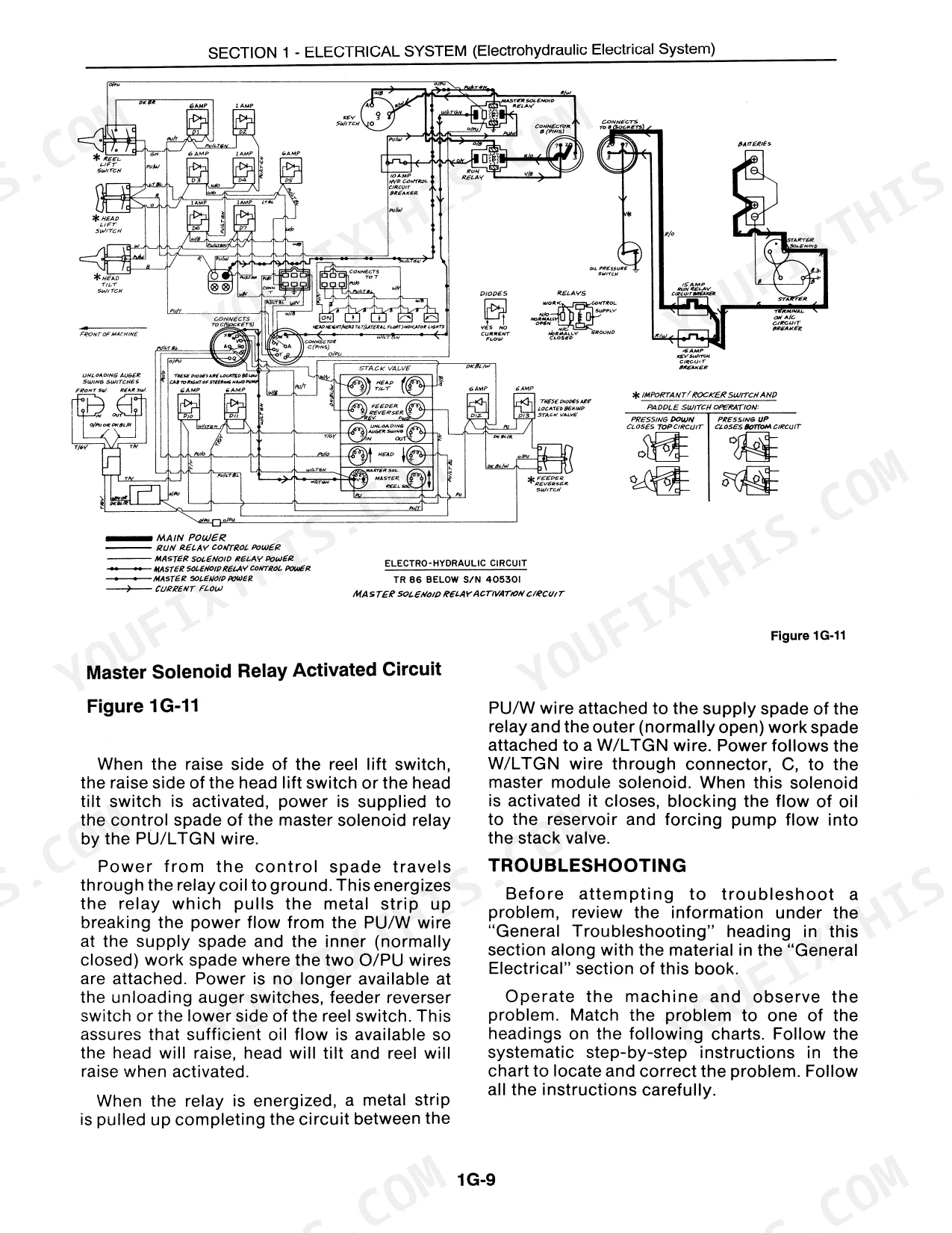
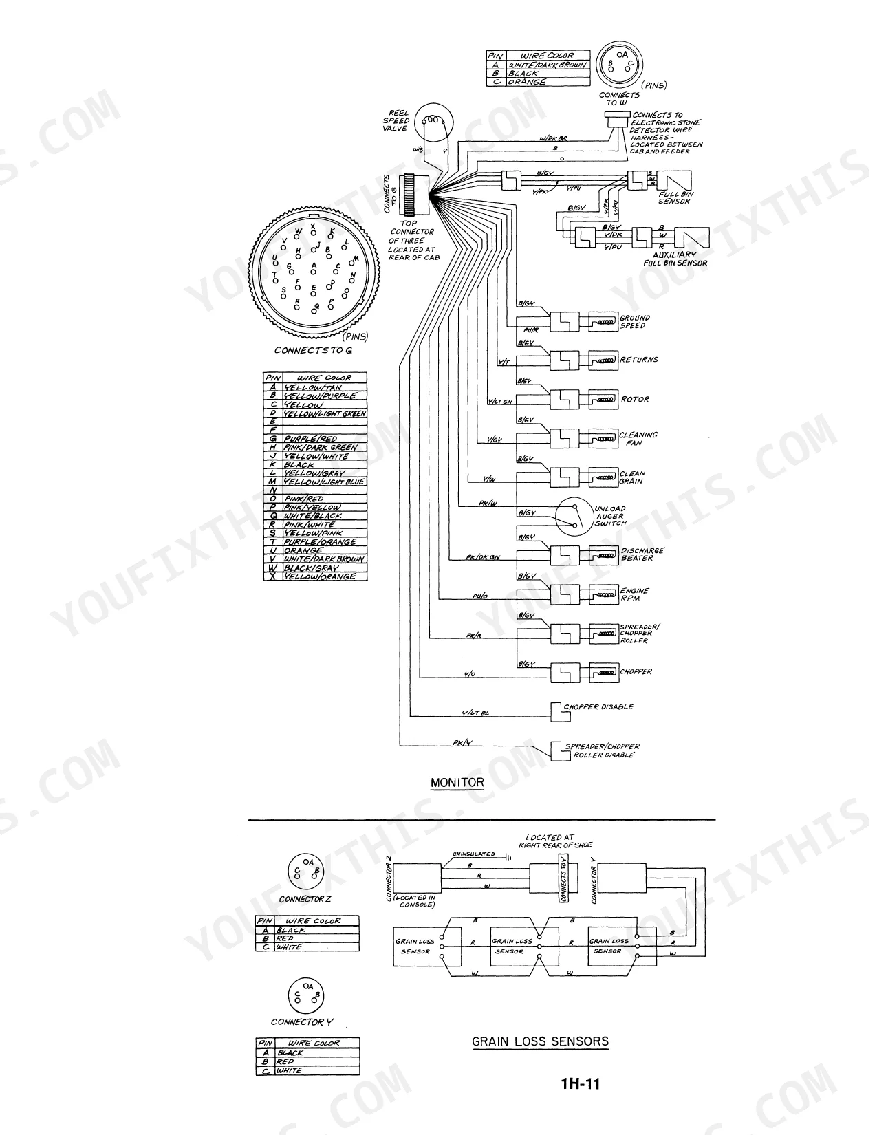
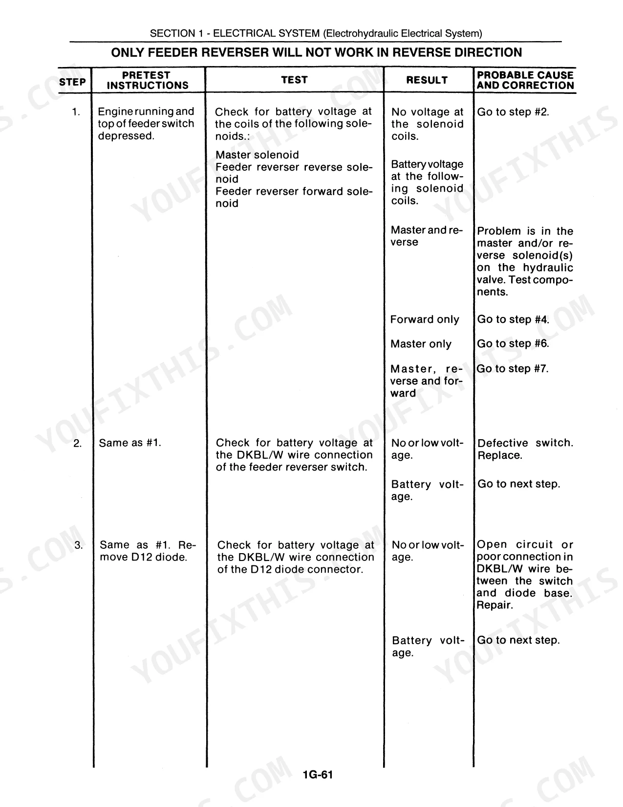
| Electrical System and Monitor | Wiring Diagrams, Starting and Charging Systems, Battery, Monitor System and Sensors, Lighting and Warning Systems, Switches, Fault Diagnosis | |
| Air Conditioning and Cab | Operator Cab, Air Conditioning and Heating, Compressor and Pressure Switches, Compressor Clutch, Controls and Instruments, Fault Diagnosis, Service |
Quick Reference Specifications
| Specification | Value | Page |
|---|---|---|
| All models | ||
| Threshing System | Twin Rotor threshing and separation | |
| Model Coverage | TR86, TR87, TR88 | |
| TR86, TR87 | ||
| A/C Low Pressure Safety Switch | 4 psi (0.27 bar) | |
| A/C High Pressure Safety Switch | 365 psi (24.8 bar) | |
| A/C Compressor Clutch Coil Resistance | 2.5 to 2.7 ohms | |
New Holland New Holland TR86 TR87 TR88 Common Problems This Manual Covers
Poor threshing, high grain loss or grain damage.
Work the Twin Rotor Threshing and Separation section: it covers the rotor speed, the concave and grate clearance and the rasp-bar condition and gives the functional adjustments and grain-loss checks to balance a clean sample against grain damage.
Manual Section: Twin Rotor Threshing and SeparationFeeder slugs, slips, or feeds unevenly.
Work the Feeder section: it covers the feeder conveyor and drive, the feed beater and the stone retarder and gives the adjustments and overhaul to stop the slugging and uneven feeding.
Manual Section: FeederDirty grain sample or grain loss over the shoe.
Work the Cleaning section: it covers the sieve and chaffer settings and the fan airflow and gives the functional adjustments and grain-loss checks to get a clean sample and keep the losses down.
Manual Section: CleaningAir conditioning cuts out or will not cool.
Work the Air Conditioning and Cab section: the A/C pressure switches (low 4 psi, high 365 psi) protect the compressor, and it gives the switch checks, the compressor clutch resistance test and the refrigerant diagnosis to get the cab cooling again.
Manual Section: Air Conditioning and CabFrequently Asked Questions
Does the manual cover the twin rotor threshing and separation adjustments?
Yes. The Twin Rotor Threshing and Separation section covers the rotors, the rotor drive and gearboxes, the rasp bars, the concaves and separator grates and the rotor speed, with the functional adjustments and wear-parts replacement to keep threshing clean and cut grain loss.
The feeder is slugging or the separator clutch slips - what does the manual cover?
The Feeder and the Engine PTO and Separator Clutch sections cover the feeder conveyor and drive, the stone retarder and the separator clutch and belts, with the adjustments and overhaul to stop slugging and clutch slip.
Does this manual include the wiring diagrams and electrical diagnostics?
Yes. The Electrical System and Monitor section carries the wiring diagrams, the starting and charging systems, the monitor system and sensors and the warning systems, so you can trace an electrical fault on the TR86, TR87 or TR88.
The air conditioning is cutting out - what are the switch settings?
The A/C low pressure safety switch is set at 4 psi and the high pressure switch at 365 psi, and the compressor clutch coil reads 2.5 to 2.7 ohms. The Air Conditioning and Cab section covers the compressor, the pressure switches and the diagnosis for an A/C that cuts out.
Which models and threshing type does this manual cover?
It covers the New Holland TR86, TR87 and TR88 twin rotor combines, including the engine PTO, feeder, twin rotor threshing and separation, cleaning, grain handling and unloading, hydraulics and electrical systems.
Is this New Holland TR86, TR87, TR88 Repair Manual a digital download?
This is a 1900-page searchable PDF (578 MB) ready for immediate download. Works on any device, so pull it up on your phone while you're under the hood. No shipping, no waiting.
Are there any print restrictions on this New Holland TR86, TR87, TR88 manual?
Absolutely. No DRM or copy protection. Print the whole manual or just the pages you need. Any home or office printer works.


Reviews
There are no reviews yet.