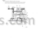
![Same Diamond 230 260 Repair Manual [Tractor]](https://youfixthis.com/wp-content/uploads/2012/02/Manual_Download-300x300.jpg)
Factory Service Repair Manual For Same Same Dorado 55 60 65 70 75 85 Tractors. Step by step Instructions, illustrations, diagrams.
PDF Manual:
Instant download: You will receive link for download on your email immediately after payment.
Compatible with PC, MAC/ Tablet / Smartphone
Searchable PDF
NOT a scan
Bookmarks
Printable: pages or entire manual
Zoomable: detailed exploded diagrams, picture
Models
Same Dorado Tractors
55
60 65
70 75
85
Contents
Main sections:
Introduction
Safety sections
Tractor configurations
Dimensions and weights
Prescribed lubricants and capacities
Conversion tables
Parts
– ENGINE
Engine section
General characteristics
Timing specifications
Lubrication system – specifications
Fuel supply system – specifications
Turbocharger – specifications
Cooling system – specifications
Engine cylinder block
Installing bushings into the camshaft journals
Adjusting backlash between the gear teeth of the auxiliary engine drive
Support for hydraulic pumps or air compressor located between engine block and timing cover
Timing idler gea
Cylinders
Main bearings
Crankshaft
Connecting rods – connecting rod bearings and bushings
Pistons
Piston rings
Counterweights for -cylinder engines
Engine flywheel
Checking camshaft
Checking camshaft bushings
Checking timing gear
Cylinder heads – valves – valve rockers
Cleaning cylinder heads
Checking engine compression
Oil pump
Checking pressure relief valve
Fitting shims between engine oil pan and front support
Fuel injection nozzles
Mechanical-type engine governor
Assembly of the governor unit
Fitting and adjustment of the external controls of the mechanical governor
Engine governor control assembly
Electronic engine governor
Installing and checking the pick-up
Installing and checking actuator
Fitting and checking the accelerator pedal (st version)
Fitting and checking the accelerator pedal (nd version)
Fuel injection pumps
Injection pump control system
Installing injection pump control bar guide supports
Engine timing
Positioning the pumps
Fuel prefilter
Fuel filter
Draining water from fuel filter
Fan assembly
Turbocharging
Engine air filter
Tightening torques
Instructions for engine assembly
Diagnosing malfunctions
– CLUTCH
Gearshift clutch
General specifications
Spring specifications to Belleville washer for the clutch engagement
Cecking clutch
Adjusting clutch control pedal
Bleeding air from the hydraulic circuit
Stripping the slave cylinder
Stripping the master cylinder
Diagnosing malfunctions
Agroshift unit, general specifications
AGROSHIFT unit detach from the gear box
Assembly of AGROSHIFT unit
Re-assembly of the Agroshift unit
Fitting the oil manifolds of the Agroshift unit
Diagnosing malfunctions
– TRANSMISSION
General specifications
Technical specifications
Speed change configurations
Section through transmission
Section through transmission with Agroshift unit
Range selector rods and forks
Removal and refitting operations
Separating the front gearbox from the engine
Dismantling the gearbox
Removal of the gearbox input and PTO shafts
Separating the AGROSHIFT unit from the gearbox
Removal of the gear train positioned in the front gearbox
Disassembly of the inversor control rods and forks
Dismantling of the gearchange rod and fork assembly
Dismantling of the gearchange selector rods and forks assembly
Removal of the shaft with the actuator for engagement/disengagement of the front-wheel drive
Removal of the range gear shaft
Examining parts removed
Adjusting play of the gearbox shafts by means of the thrust plates on the mini/inversor
shaft and the secondary shaft
Warnigns related to assembly of the gears of the PTO unit, the range reduction unit and synchronised
PTO shaft
Assembly of the PTO
Installation of the range reduction unit, the gear for the front-wheel drive shaft
and the parking brake discs
Points where sealant is to be used
Tightening torques
Bevel drive adjustment
Servicing operations
Rear power take-off
PTO clutch
Technical specifications
Correct positions of PTO sensors and cables
Clutch inspection
Checking clutch hydraulic pressures
Checking the end-play of the front shaft of the PTO clutch
Renewal of the rear PTO clutch
Main operations for removal of the rear PTO unit
Diagnosing malfunctions
– AXLES
Rear axle
Installing the rear half-shafts
Removal and disassembly of the epicyclic reduction unit
Fitting lateral stub axles of the wheel
WD extendible axle
Removing the axle from the front support
Centre steering lever
Wheel hub
End float adjustment
Front-wheel drive
Specifications
Epicyclic reduction unit
Side hubs
Tightening torques
Adjusting bevel gears
Adjustment of the internal control of the mechanical differential lock
Installing the differential assembly into the drive axle
Diagnosing malfunctions
– VEHICLE
Brakes – General information
Hydraulic pump
Assembly of brake master cylinder
Checking the front brake disks on WD and WD front axles and the rear brake disks
Adjusting service brake pedals
Correct installation of inspection cover for parking brake discs
Checking parking brake pads
Bleeding air from the brake hydraulic system
Separate Brakes valve
Diagnosing malfunctions
Hydraulic lift with load sensing
Installing the lift and front cover plate of the gearbox
Lift mechanism
Checking the safety valves
Checking the protrusion of the non-return valve
Adjusting the lift
Lift hydraulic circuit
Sensing arm assemblyMontaggio dell’organo sensibile
Power-lift distributor valve spring setting specifications
Electronic lift
Control panel
Control level or depth control knob
Mix position/draft control
Lowering speed control knob
Maximum lift height control knob
Up/Down control switch
Up control
Control/Float mode
Lift status indicator light
Remote pushbuttons for lift operation from ground
Calibration of the AUTOMATIC
Lift operation
Electronic circuit diagram of the ECU
Calibration of the AUTOMATIC
Emergency manual lift control
List of electronic lift tests
Position sensor calibration
Precautions for electronic equipment
Checking the electronics system
Checking mechanical components
Front hydraulic liftSollevatore idraulico anteriore
Hydraulic accumulator and antishock valve for front lift
Front power take-off – General information
Section of the PTO
Fitting the “RING-FEEDER” rings
Checking the clutch
Diagnosing malfuntions
Spring specifications
– CONTROLS
Hydrostatic steering
Inspections and checks
Steering pump
Directional control valve
Check the setting of the pressure relief valve
Bleeding the hydraulic circuit
Assembly of orbital pump unit
Teering wheel shaft and steering cylinders
Instructions for the hydrostatic steering distributor assembly
Diagnosing malfuntions
Mechanical controls
Electro-hydraulic controls
Front PTO clutch engagement control
Rear PTO clutch engagement control
Differential lock engagement control
Front-wheel drive engagement control
Rear PTO engagement control
Gearbox
Front and rear lift
Hydraulic circuit diagram
Solenoid valve – Specifications
Adjustment of front and rear differential lock control
– BODYWORK
Platform
Cab – General information
Cab air filter
Screen wash
Screen wipers (front and rear)
Removing the driving platform complete with cab
Breakage of the top hood release cable
High visibility cab roof
– SYSTEMS
Ventilation
Heating System
Air conditioning unit for cabs
Operation and maintenance of the air-conditioning system
Water dripping from the points at which condensate drain lines are connected to the conditioning unit
Checking system
System safety elements
Temperature regulation
Charging the system
Filling the metering unit
Refilling the system with oil
Verifying operation of the system after recharging
Directions for tightening air conditioning system pipeline fittings
Diagnosing malfuntions
Hydraulic system
Oil filters
Hydraulic pumps
Checking the relief valves of the hydraulic lift system
Stripping the hydraulic pump
Auxiliary hydraulic spool valves
Checking the pressure relief valve setting
Checking the operating pressure
Conversion of auxiliary spool valves from double acting to single acting operation
Checking the surface of the valve spools
Trailer hydraulic braking system
Trailer hydraulic braking distributor unit
Use of the tractor with CUNA / hydraulic trailer braking
Starting
Installing the hydraulic braking valve for trailers equipped with safety brake
electrical system DORADO – (up serial number ) –
electrical system DORADO – (under serial number )
General safety directions
Jump start utilizing another battery
Recharge system
Heating system-
Heating and conditioning system
Starting system
Ignition key –
Ventilation control
Push button control –
-Speed windscreen wiper switch
Work ligths
Screen washer switch
Beacon push button
Push button AGROSHIFT
Relay
Electronic flasher unit
Switch controlling
Switch controlling: differential lock – PTO clutch – RM – rpm/min PTO speed selector –
Economy PTO – Live Pto – electric starter system
Switch for emergency brake
Fuse box
Instrument panel with digital display
Operation of the broken belts alarm control unit
Engine stop operation with a type MH engine control unit
Electrical wiring
– APPENDIX
Engine electronic unit I
Power lift tester version a XLVII
Power lift tester version a LXV