


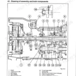
This SAME EXPLORER II Special Workshop Manual is the factory service publication for the 70, 75, 80, 85, 90, and 95 HP tractors, covering publication 307.1130.3.0 across 458 pages in English. It is written for the technician doing real repair and overhaul work, not just routine service.Inside you get the procedures for the transmission and shuttle, front axle, rear PTO, hydraulic and steering circuits, braking system, clutch, electrical system, and the cab, ROPS, and sheet-metal removal. Each section gives removal and refitting steps, adjustment data, wear checks, and tightening torques.Note that detailed engine internal servicing is handled in the separate SDFG engine manual (code 307.1072.3.5); this book covers engine separation, clutch, and everything around the engine on the tractor. If you own or service one of these EXPLORER II Special models, this is the reference that lets you diagnose faults and rebuild assemblies correctly.
What's Inside This Same Explorer II Special 70-95 HP Manual
| System | Pages | Key Topics |
|---|---|---|
| General Information & Safety | - | Manual Structure, Safety Notes, Symbols Used, Standard Tightening Torques, Conversion Factors |
| Transmission | - | Gearbox & Shuttle Assembly, Differential Lock, Bevel Gear Pair Adjustment, PTO Drive Shaft, Main Shaft Disassembly |
| Rear PTO | - | PTO Control Clutch Operation, 2-Speed PTO Mechanism, PTO Input Shaft Removal, PTO Clutch Disassembly, Groundspeed PTO Engagement |
| Front Axle | - | Final Drive Reduction Unit, Differential Lock Adjustment, Bevel Gear Pair Disassembly, Steering Knuckle Housing, Wheel Hub Assembly |
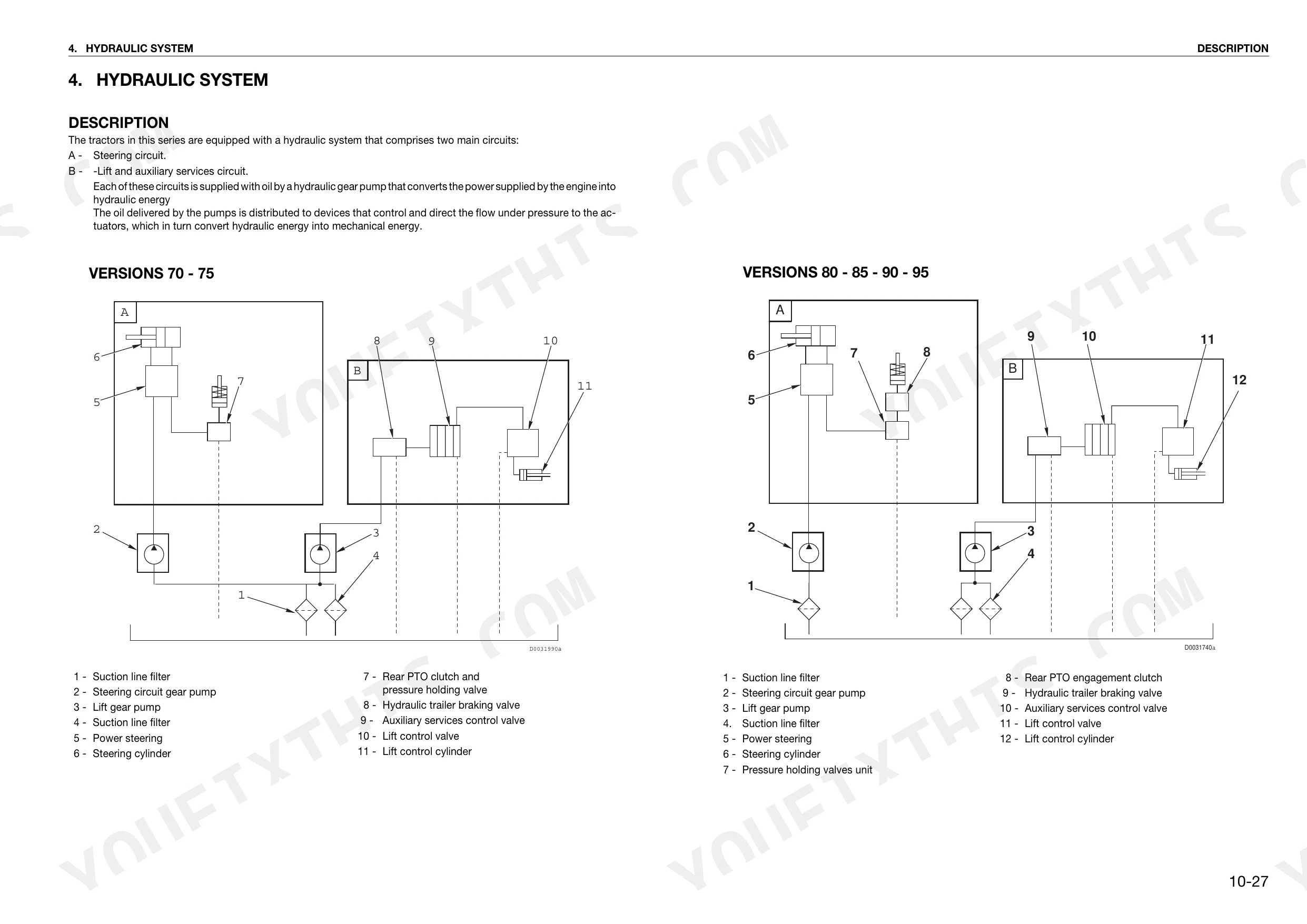
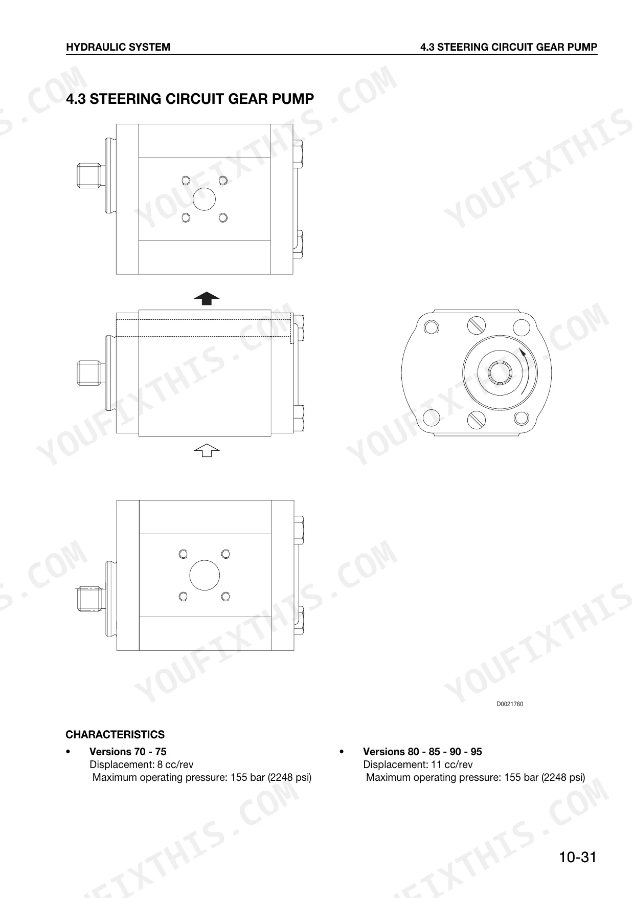
| Hydraulic System | - | Hydraulic Diagrams, Steering Circuit Gear Pump, Lift Control Valve Operation, Auxiliary Services Control Valve, Power Steering Pump Removal |
| Braking System | - | Trailer Braking Valve Operation, Separate-Brakes Valve Function, Rear Axle Brake Piston Disassembly, Parking Brake Disassembly, Brake Bleeding Procedure |
| Front Hoods & Radiator | - | Front Hoods Removal, Radiator Removal, Coolant Draining, Filter Support Removal |
| Engine & Clutch Assembly | - | Engine Separation Preparation, Clutch Plate Wear Check, Thrust Bearing Renewal, Master Cylinder Removal, Clutch Control Circuit Bleeding |
| ROPS Frame & Fenders | - | ROPS Frame Removal (T58-T62/T42-T45), Safety Roll Bar Removal, Fenders Removal |
| Wheels & Tires | - | Front Wheels (4WD/2WD) Removal, Rear Wheels Removal, Tire Flexure Elimination |
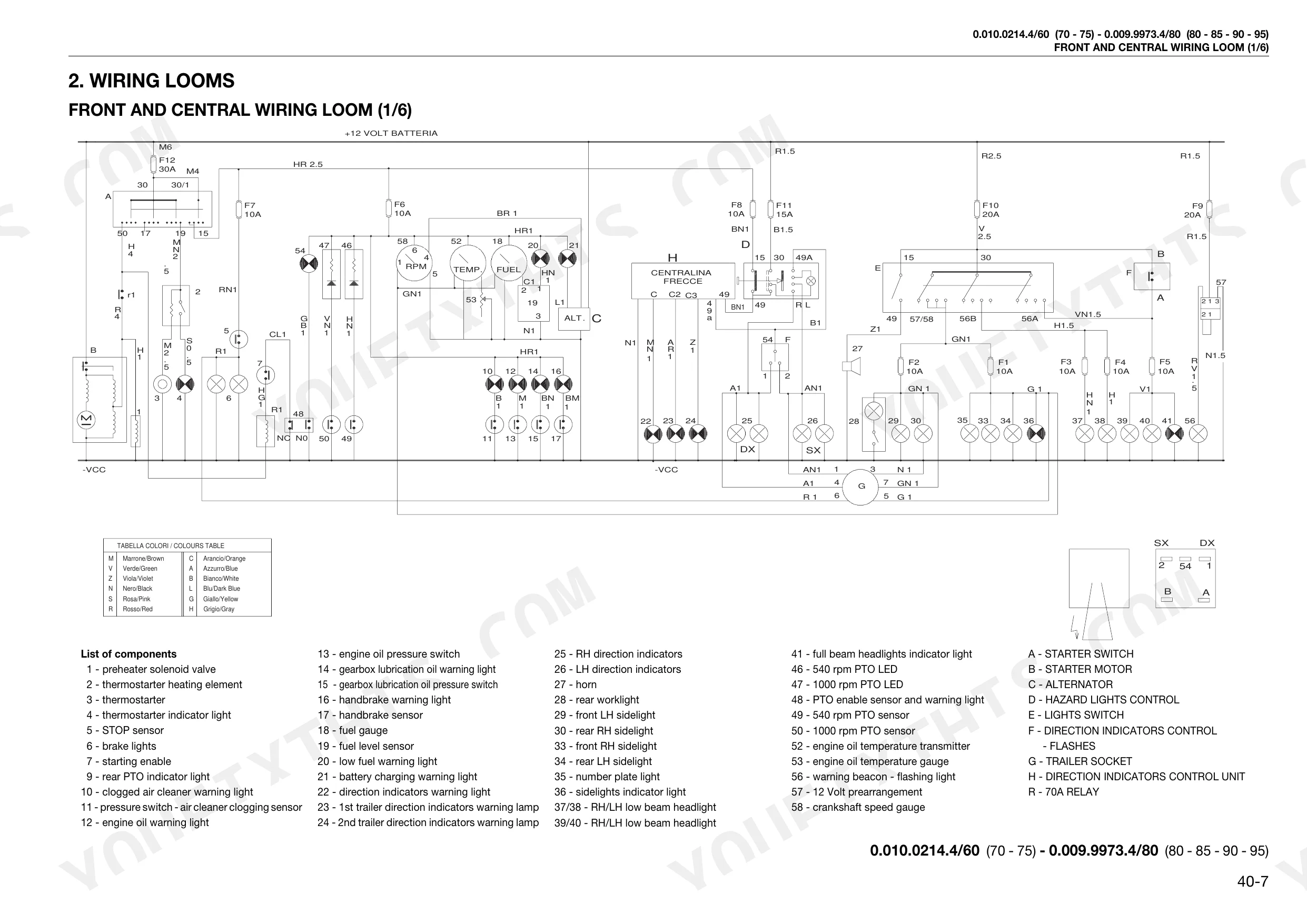
| Electrical System | - | Wiring Loom List, Component Definitions, Wiring Faults, Connector Maintenance, Wire Colour Codes |
| Instrument Panel & Fuel Tank | - | Instrument Panel Removal, Fuel Tank Removal, Fuel Level Sensor Disconnection |
| Seat Support | - | Seat Support Removal, Collapsible Safety Roll Bar Version, ROPS Version |
Quick Reference Specifications
| Specification | Value | Page |
|---|---|---|
| Engine separation bolts and nuts torque | 40±2 Nm (29.5±1.5 lb.ft.) | p. 218 |
| Front wheels (4WD version) screws torque | 377±38 Nm (277.8±28.0 lb.ft.) | p. 101 |
| Front wheels (2WD version) nuts torque | 357±36 Nm (263.1±26.5 lb.ft.) | p. 102 |
| Diagnostic instrument required | Digital multimeter (AC VOLT 0-600, DC VOLT 0-600, OHM 0-32M, AC AMP 0-10, DC AMP 0-10) | p. 441 |
| Electrical connector replacement condition | replace it with a new one if damaged, deformed or broken | p. 440 |
| Electrical components (fuses, relays) replacement | use only original parts supplied by the manufacturer; fuses must conform to DIN 72581 or ISO 8820 standards | p. 440 |
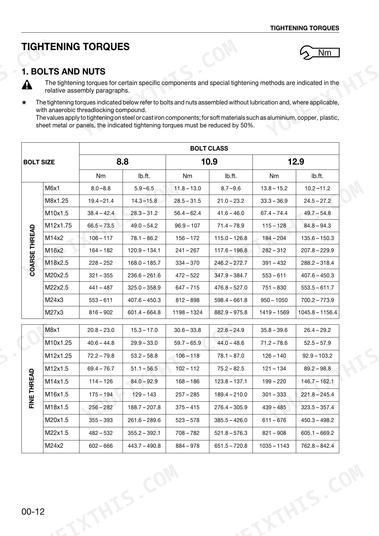
| Bolt Tightening Torque (M6x1, 8.8 class) | 8.0-8.8 Nm | p. 15 |
| Bolt Tightening Torque (M10x1.5, 10.9 class) | 56.4-62.4 Nm | p. 15 |
| Bolt Tightening Torque (M24x3, 12.9 class) | 950-1050 Nm | p. 15 |
| Fittings Tightening Torque (M20x1.5) | 65 Nm | p. 16 |
| Hex Plugs Tightening Torque (M10x1) | 14 Nm | p. 17 |
| Engine Coolant Capacity | 12 l | p. 94 |
Same Explorer II Special 70-95 HP Common Problems This Manual Covers
Intermittent electrical faults
Lights, gauges, or the starting circuit behave unreliably because of poor connector contact or wiring faults, which the manual specifically calls out. The Electrical System section walks through the wiring loom, connector maintenance, and wire colour codes to trace the break.
Manual Section: Electrical SystemClutch drag or slipping
Worn clutch plates or a failed thrust bearing cause slip under load or a clutch that will not fully disengage. The Engine & Clutch Assembly section covers the plate wear check, thrust bearing renewal, and clutch control circuit bleeding.
Manual Section: Engine & Clutch AssemblyHeavy or erratic power steering
A weak steering gear pump or a mis-set relief valve makes the steering heavy or inconsistent. The Hydraulic System section covers the steering circuit gear pump, lift control valve operation, and power steering pump removal.
Manual Section: Hydraulic SystemSpongy or uneven brakes
Air in the brake circuit or a worn rear axle brake piston gives a spongy pedal or pulls to one side. The Braking System section covers the brake piston disassembly, separate-brakes valve function, and the bleeding procedure.
Manual Section: Braking SystemRear PTO will not engage
A worn control clutch or low modulation pressure keeps the rear PTO from engaging cleanly or holding under load. The Rear PTO section covers the control clutch operation, the 2-speed mechanism, and PTO clutch disassembly.
Manual Section: Rear PTOFront axle differential lock trouble
A differential lock that fails to hold or disengage, or noise from the final drive, points to the front axle. The Front Axle section covers the final drive reduction unit, differential lock adjustment, and the steering knuckle housing.
Manual Section: Front AxleFrequently Asked Questions
Which tractors does this manual cover?
It covers the SAME EXPLORER II Special in 70, 75, 80, 85, 90, and 95 HP versions, under publication number 307.1130.3.0. It is the factory Workshop Manual for these tractors, running 458 pages in English.
What are the wheel bolt torque figures?
The front wheels tighten to 377 plus or minus 38 Nm on the 4WD version and 357 plus or minus 36 Nm on the 2WD version, and the rear wheels to 500 Nm. The Wheels & Tires section gives the full removal and torque values. p. 101
Does this manual cover engine internals?
It covers engine separation from the tractor, clutch work, and the surrounding systems; the engine separation bolts torque to 40 plus or minus 2 Nm. Detailed internal engine servicing is in the separate SDFG engine manual, code 307.1072.3.5. p. 218
Can I diagnose electrical faults with it?
Yes. The Electrical System section covers wiring faults, connector maintenance, and wire colour codes, and specifies a digital multimeter for testing. Damaged connectors should be replaced with new original parts rather than repaired. p. 441
What do I get after purchasing this Same EXPLORER II Special 70 HP & variants?
A 458-page searchable PDF, ready to download the moment you buy. It works on any device, so you can pull it up on your phone while you're under the hood. No shipping, no waiting.
Reviews
There are no reviews yet.