


![Same Deutz-Fahr 393 453 503 603 Repair Manual [Tractor]](https://youfixthis.com/wp-content/uploads/2015/07/Same-DF-1-300x300.jpg)
![Same 85 100 Explorer 3 Series Repair Manual [Tractor]](https://youfixthis.com/wp-content/uploads/2017/02/2017-02-15_15-10-09-300x300.jpg)
Factory Service Repair Manual For Same Silver 110 130 Tractor. Step by step Instructions, illustrations, diagrams for quality servicing and repair. Just like the original factory paper manual. In this version included Electrical Schematics, Hydraulic Schematics.
PDF Manual:
Instant download – You will receive the link for download on your email immediately after payment.
Lifetime access to download (by request)
Compatible with Windows, IOS, Android and other systems
Searchable Text and Built-in index for instant information search
Bookmarks
Printable – pages or entire manual
Zoomable – detailed exploded diagrams, picture
Models
Same Silver 110
Same Silver 130
Contents
General information
Characteristics and Data
Engine
Clutch
Gearbox
Rear Transmission
Power take-offs
Brakes
Axles and Wheels
Steering
Cab
Hydraulic system
Electrical-Electronic System
Troubleshooting
Complete Contents:
General information
Safety rules
– General information
– Starting
– Operation
– Stopping
Maintenance
– General information
– Engine
– Electrical system
– Hydraulic system
– Tyres and wheels
– Recognise the safety warnings
– Understand the safety terms
– Protecting the environment
– Follow the safety rules
– Prepare for emergencies
– Wear protective clothing
– Protect yourself against noise
– Inspect the tractor
– Use the handholds and steps
– Adjust the driver’s seat
– Fasten the seat belts.
– Only operate the tractor from the driver’s seat
– Never carry passengers on the tractor
– Warn others that maintenance work is in progress.
– Keep well clear of moving parts
– Protect yourself from flying splinters
– Dispose of all waste in an appropriate manner
– Work in a clean area
– Ensure the work area is well illuminated
– Wash the tractor regularly
– Avoid acid burns
– Starting the engine using auxiliary batteries
– Avoid battery explosions
– Avoid burns
– Keep the tractor clean
– Be careful of fluids under pressure
– Avoid the danger of bursting tyres
– Handle fluids safely – Prevent fires
– Prevent fires
– Evacuation in case of fire
– Exhaust gas
– Use the proper tools
– Do not apply heat near pressurised pipes
– Do not heat pipes containing inflammable fluids.
– Remove paint before welding or heating parts
Characteristics and Data
Dimensions and weights
Technical data
– Clutch
– Gearbox
– Rear PTO
– Front PTO
– Ground speed PTO
– Front axle
– Brakes
– Steering
– Hydraulic rear lift
– Front lift
– Cab and electrical system
Speeds
– 18+18 Gearbox – Speeds in km/h with 520/70R38 tyres
– 24+24 Gearbox- Speeds in km/h with 520/70R38 tyres
– 24+12 Gearbox – Speeds in km/h with 520/70R38 tyres
– 36+18 Gearbox- Speeds in km/h with 520/70R38 tyres
– 48+24 Gearbox- Speed in km/h with 520/70R38 tyres
– 72+72 HML Gearbox- Speeds in km/h with 520/70R38 tyres
– Tractor and implement combination
– Rear implement and front and/or rear implement combinations
– Mounted front implement
Engine
Engine removal
Refitting the engine
Final operations
Clutch
Removal of the clutch
– Separation of the tractor between the engine flange and intermediate transmission casing
Disassembly of the clutch
– Cab side
– Engine side
Clutch overhaul
– Checks
Clutch assembly
– Engine side
– Cab side
Refitting the clutch
– Re-attachment of the engine flange to the intermediate transmission casing
– Bleeding the hydraulic clutch system
Gearbox
Removal of gearbox from rear transmission casing
– Disassembly of the super-reduction
– Removal of the lift oil filters
Gearbox disassembly
– Removal of the fast range gears and shuttle from the gearbox/rear transmission casing flange
Refitting the gearbox
– Refitting the fast and shuttle gears on the gearbox/rear transmission casing flange
– Calculation of the shim thickness for end float adjustment of the reduction gear shaft
– Assembly of gearbox to rear transmission casing
– Refitting the lift oil filters
– Primary shaft end float adjustment
– Assembly of the super-reduction unit
– Adjustment of the HML unit end float
Overhaul of the HML unit
– Disassembly
– Assembly
– Gearbox/transmission diagram
– HML control valve diagrams
– Gearbox detail
– HML clutches detail
– Components of the “L” and “SR” reduction control
– “L” and “SR” reduction control diagram (1)
– Components of the shuttle control (1)
– Components of the 1st -2nd speed control (2)
– Shuttle (1) and 1st -2nd speed (2) control diagram
– Components of the 3rd -4th speed control
– 3rd -4th speed control diagram
– Components of the shuttle control
– Components of the gear control
– Shuttle and gear control diagram
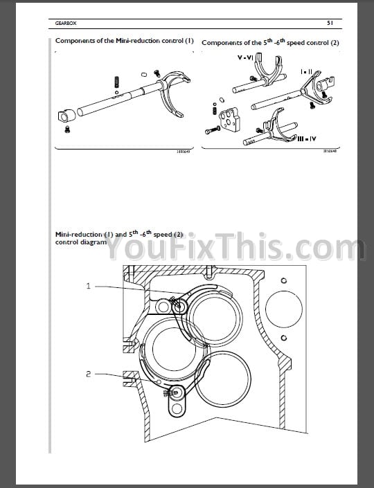
– Components of the Mini-reduction control (1)
– Components of the 5th -6th speed control (2)
– Mini-reduction (1) and 5th -6th speed (2) control diagram
– Components of the “V” and “N” reduction control
– “V” and “N” reduction control diagram
Rear Transmission
Disassembly of the rear transmission casing
– Checks and adjustments
– Checking the play between the 4WD clutch plates
Assembly of the rear transmission casing
– Assembly of the ground speed PTO
– Assembly of the PTO
– Assembly of the parking disc brakes
– Assembly of the 4WD clutch
Adjustment and assembly of the bevel drive
– Adjustment of the crown wheel bearing preload
– Adjustment of the pinion mounting distance
– Adjustment of the crown wheel-pinion backlash
Rear differential with mechanical locking
– Diagramme of rear differential with mechanical locking
– Diagramme of rear differential with electro-hydraulic locking (2-planet version)
– Rear differential with hydraulic control (4-planet version)
Power take-offs
Disassembly of the power-take-offs
– Disassembly of the PTO
– Removal of the PTO clutch
– Disassembly of the PTO
– Disassembly of the ground speed PTO
Assembly of the power take-offs
– Assembly of the ground speed PTO
– Assembly of the PTO
– Refitting the PTO clutch
– Assembly of the economy PTO
Checks and adjustments
– Adjustment of economy PTO engagement
– Adjustment of the PTO selector rod
– Checking the play between clutch plates in the hydraulic PTO clutch
Brakes
Disassembly of the front brakes
Assembly of the front brakes
– Bleeding the front brake circuit
Disassembly of the rear brakes
Assembly of the rear brakes
– Calculation of brake adjustment shim thickness
– Bleeding the rear brake circuit
“Separate brakes” valve
– Right pedal only depressed (OFF)
– Left pedal only depressed (OFF)
– Right pedal only depressed (ON)
– Left pedal depressed only (ON)
Axles and Wheels
Removal of the front axle
– Preliminary operations
Refitting the front axle
– Final operations
Removal of the front differential
– Preliminary operations
Refitting the front differential
– Final operations
Overhaul of the front differential
– Disassembly
– Assembly
– Adjustment of the bevel drive
Removal of front axle components
– Preliminary operations
– Removal of the front reduction unit
– Disassembly of the front brakes
– Disassembly of the stub axle housing
– Removal of the front halfshaft
Refitting the front axle components
– Refitting the front halfshaft
– Assembly of the stub axle housing
– Adjustment of the kingpin bearing preload
– Assembly of the front brakes
– Refitting the front reduction unit
– Final operations
Overhaul of the front reduction unit
– Disassembly
– Assembly
– Shimming the bearings of the reduction unit
Overhaul of the constant velocity joints
– Disassembly
Removal of the rear reduction unit
– Assembly
– Disassembly of the halfshaft and planet carrier
– Assembly of the halfshaft and planet carrier
– Adjustment of the rear halfshaft bearings
Refitting the rear axle casing
Extendible halfshaft
– Disassembly
– Assembly
– Adjustment of the differential lock disc play
– Adjustment of the differential lock
– Adjustment of the differential lock engagement control
– Section views of extendible halfshaft
Steering
Disassembly of the power steering unit
– Main safety valve
Assembly of the power steering unit
– Preliminary operations
– Instructions for O-ring/Kin-ring assembly
– Assembly of the non-return valve
– Anti -cavitation valves
– Main safety valve
– Checking the setting of the main safety valve
Cab
Removal of the cab
Refitting the cab
– Final operations
Hydraulic system
Removal of lift and components
Refitting the lift unit
Overhaul of the power lift
– Disassembly
– Assembly
Overhaul of hydraulic pumps
– Disassembly
– Checks and adjustments
– Assembly
Electronic lift control valve
– Component positions
– Oil conditions
– Control valve in lifting condition
– Control valve in neutral condition
– Control valve in lowering condition
– Hydraulic schematic
Overhaul of the mechanical lift control valve
– Checks with control valve assembled
– Disassembly of the control valve
– Checks and adjustments
– Assembly
– Adjustment of Max Lifting
– Adjustment of the safety stop
– Checking Float operation
– Counterweight drop test (with counterweight of at least 200 kg)
– Adjustment of the position control lever
– Adjustment of the draft control lever
– Sensitivity control
Sensing devices
– Dismantling the electronic lift sensing device
– Dismantling the mechanical lift sensing device
Sensing device components
– Electronic lift
– Mechanical lift
– Front hydraulic lift
Electrical-Electronic System
– General Warnings
– General precautions for electronic components
– Earthing and electromagnetic compatibility
– Practical hints
General description of the system
– System characteristics
– Fuse and relay box
Cab
– Position of components in the cab
– Central instrument panel (dashboard)
– Right-hand instrument panel – DATA monitor
– Calibration of the DATA monitor
– Instrument operation test
– Electronic lift
– Description of the operation of the PTO control unit
– Description of the operation of the HML electronic control unit
– Description of components
– Battery (maintenance-free type)
– Bosch 3KW starter motor
– 85A Alternator with “W”
– Starter switch
– Steering column switch unit
– Multifunction control on armrest
– Hand throttle
– Direction indicators control unit
– Electronic governor control unit
– HML control unit
– S.B.A. control unit (Option available only with mechanical rear lift)
– Rear PTO control unit
– Preheating control unit
– Glowplug
– Check panel
– Engine oil pressure gauge
– Battery voltage gauge
– Coolant temperature gauge
– Fuel gauge
– 30 Km/h multimeter
– 40 Km/h multimeter
– Upper worklights switch
– Lower worklights switch
– Rear worklights switch
– Flashing light control switch
– Corner worklights switch
– Rear screen wiper switch
– Hazard warning lights switch
– Heating fan switch
– [Engine speed inductive sensor
– Lift draft sensor (60KN)
– Lift position sensor and steering angle sensor
– Accelerator pedal potentiometer
– Windscreen wiper motor
– Rear screen wiper motor
– Fuel level sender
– Compressor for R134a
– Receiver-drier for R134a
– Outlet socket (+12V)
Bulkhead connectors
Key to wire colours
Diagnostic instruments
– List of components
– List of fuses
– List of relays
– List of ground connections
– List of wiring connections
Wiring key
Functional card key
– Table I – Components on rear frame
Location of components on vehicle
– Table 2 – Components on front frame
– Table 3 – Upper cab components
– Table 4 – Lower cab components
Example (electrical wiring diagrams and wiring)
Example of fuel level system fault.
– 1,2 – Battery wires 0.011.5844.4
Wiring
– 3,4, 5- Front wiring 0.011.5840.4
– 6 – Central wiring 0.011.5836.4
– 11 – Wiring under foot mat 0.011.5841.4
– 12 – Rear wiring 0.011.7538.4/10
– 13 – Cab overhead wiring 0.008.0400.3
– 14 – Electronic governor wiring for manipulator 0.011.5838.4
– 15 – Electronic governor wiring 0.011.5837.4
– 16 -Electronic lift wiring “SLH” 0.011.7067.4
– 17 – Conditioner wiring 0.008.0672.3/20
– 18 – Heater wire 0.009.3845.3
– 19 – Trailer brakes air pressure indicator wire 0.011.7360.4
– 20 – SBA wiring 0.011.8517.4
– 21 – Potentiometer wire (Steering angle sensor) SBA 0.011.7181.4
– 22 – Electronic SBA button wire 0.010.1510.3
– 21 – Potentiometer wire (Steering angle sensor) SBA 0.011.7181.4 (topographical)
– 21 – Electronic SBA button wire 0.010.1510.3 (topographical)
– 23 – Italia brakes wire 0.011.9429.4
– 24 – Germania brakes wire 0.011.9431.4
– 24 – Germania brakes wire 0.011.9431.4 (topographical)
– Board 1 – Perspective Starting – Recharge – Pre-heating
Functional boards
– Board 2 – Perspective Instruments
– Board 3 – Perspective Visual indicators
– Board 4 – Perspective Interior roof lighting – Sen/ices
– Board 5 – Perspective Side/tail lights – Dipped headlights – Full beam headlights Horns – Trailer fittii
– Board 6 – Perspective Direction indicators – Hazard warning light – Vehicle stop
– Board 7 – Perspective Worklights – Flashing
– Board 8 – Perspective Windscreen and rear screen wipers
– Board 9 – Perspective Conditioner – Heater
– Board 10 – Perspective Electronic lift without SBA
– Board 10 – Topographical Electronic lift without SBA
– Board 11 – Perspective Electronic lift with SBA
– Board 12 – Perspective Electronic lift and SBA device (control unit)
– Board 13 – Perspective Electronic governor without manipulator
– Board 14 – Perspective Electronic governor with manipulator
– Board 15 – Perspective SBA device without Electronic lift
– Board 16 – Perspective PTO device
Troubleshooting
All Round Tester – connection and power up
– 5 Pedal sensor
– 6 Actuator
– 7 Engine rpm reading
Engine troubleshooting with the All Round Tester
– Presentation screen
– Engine test
– 1 Parameters display
– 2 Auto programming
– 3 Test
– 4 Manual Programming
– 8 Selfdiagnosis
Appendix 1
– Engines List -Wheel Constant
Electronic lift diagnosis with the All Round Tester

Reviews
There are no reviews yet.