
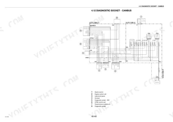
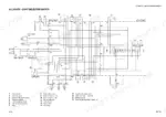
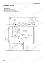
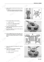
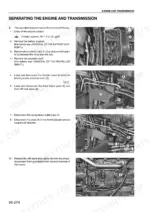
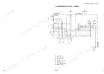
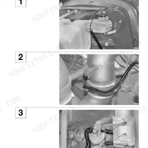
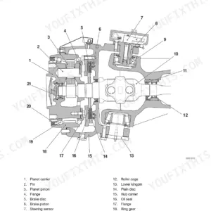
This is the full workshop manual for the SAME IRON 175S, 190S and 200S, and it goes deep where these tractors actually need it: the power shift transmission and the load sensing hydraulics. You get the H-M-L unit, shuttle, range gearbox and 18-speed transmission stripped and rebuilt step by step, the 103 l/min variable displacement pump with its load sensing and pressure control valves, plus every control valve on the machine. Diagnostics get real coverage too - the ALL ROUND TESTER hookup, SPN and FMI alarm identification, transmission pressure checks against printed reference values, and SERDIA Level III. Axles, brakes, hydraulic front suspension, PTO, power lift, cab electrics and full wiring diagrams round it out. One note: engine internals are in the separate Deutz 1012/1013 manuals, not here.
What's Inside This Same IRON 175S, IRON 190S, IRON 200S Manual
| System | Pages | Key Topics |
|---|---|---|
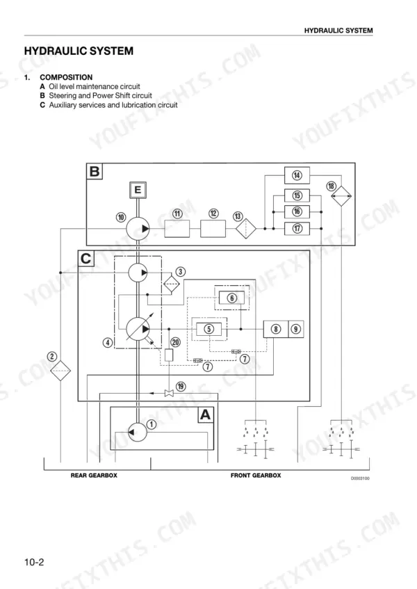
| Hydraulic System | 23-31 | Load Sensing Circuit Layout, Oil Level Maintenance, Auxiliary Services and Lubrication Circuit, Filtration and Mesh Sizes, Oil-Cooler By-Pass Valve, Front Lift Accumulator |
| Variable Displacement Pump | 32-45 | Swash Plate Delivery Control, Load Sensing Valve, Pressure Control Valve, Antishock Valve, Boost Pump, Lubrication Circuit Pressure Limiting Valve |
| Hydraulic Control Valves | 46-66 | Auxiliary Services Control Valve, Main Clutch Control Valve, Power Shift Control Valve, Services Control Valve, Range Gearbox Control Valve, Power Steering, Trailer Braking Valve |
| Power Shift Transmission | 67-84 | H-M-L Unit, Main Clutch, Intermediate Gearbox, Primary and Secondary Shafts, Range Control Unit, Shuttle |
| Front and Rear Axles, PTO and Power Lift | 85-98 | Front Axle, Rear Axle, Rear PTO, Rear Power Lift, PTO Clutch, Power Lift Control Unit |
| Braking System and Front Axle Suspension | 99-110 | Braking System, Hydraulic Front Axle Suspension, Front Suspension Control Valve |
| Electronic System Diagnostics | 111-160 | ALL ROUND TESTER Diagnostic Instrument, Connection of the Tester to the Electronic Control Units, Introduction to the Electronic System of the Tractor, Layout of Main Components |
| Putting the Tractor Into Service and Fault Finding | 161-206 | Putting the Tractor Into Service, What to Do When… List of Operations, Component Renewal, Checking and Calibration Procedures |
| Transmission Pressure Checks and Alarms | 207-384 | Checking the Hydraulic Pressures of the Transmission, Alarms, SPN and FMI Fault Identification, Alarm List on the Display |
| ECU Tester Manuals and SERDIA Diagnostics | 385-494 | Transmission Control Unit Tester Manual, HPSA Control Unit Tester Manual, Armrest Control Unit Tester Manual, SERDIA Level III |
| Component Layout, Engine Bay and Air Conditioning | 495-544 | Method for Removal and Refitting of Rigid Pipes and Wiring, Transmission and Hydraulic System Top Views, Engine Hood Side Panels and Grille, Starter Motor, Alternator and Drivebelts, Air Compressor, Air Conditioning System, Condenser, Intercooler, Radiator, Air Filter |
| Brakes, Power Steering and Front Axle Overhaul | 545-670 | Brake Master Cylinders, Bleeding the Braking System, Power Steering Unit, Front Brakes, Epicyclic Reduction Units of the Front Axle, Stub Axle Housings and Front Halfshafts, Steering Cylinders, Front Suspension Cylinders, Front Axle Differential, Front PTO, Fuel Tanks, Propeller Shafts |
| Pumps, Control Valves and Lift Unit Overhaul | 671-725 | Clutch Control Unit, Complete Pump Assembly, Testing the Auxiliary Services Pump, Pump Drive, Power Shift Control Valve, Shuttle Assembly, Range Gearbox Control Unit, Auxiliary Hydraulic Control Valves, Supplementary Lift Cylinders, Lift Draft Sensor, Lift Unit |
| Cab, Controls and Electrical Components | 726-771 | Arm-Rest Control Panel and Seat, Steering Column Switch Unit, Instrument Panel Shroud, Right and Left-Hand Consoles, Transmission Lift and Safety Device ECUs, Engine ECU, Fusebox, Accelerator Potentiometer, Heater Valve and Matrix, Air Conditioning Evaporator and Blowers, Screen Wipers, Cab and Rear Cab Mountings |
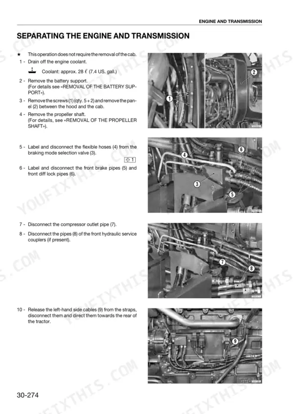
| Engine-to-Transmission Split, Gearbox and Rear Axle Overhaul | 772-962 | Engine and Transmission Separation, H-M-L Unit, Front Transmission Casing, Rear Transmission Casing, Rear Gearbox, PTO Clutch, Rear Axle and Brakes, Power Shift Cover |
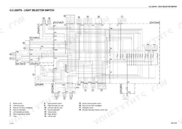
| Electrical Components, Systems and Wiring Diagrams | 963-1076 | Structure of the Unit, Indices, Components, Systems, Planimetry, Wiring Diagram and Connectors Location |
Quick Reference Specifications
| Specification | Value | Page |
|---|---|---|
| All Models | ||
| Oil level maintenance pump displacement | 19 cc/rev | p. 31 |
| Oil level maintenance pump max capacity | 51.3 l/min at 2350 engine rpm | p. 31 |
| Lubrication circuit bypass valve setting | 1.5 bar | p. 30 |
| Oil-cooler bypass valve setting | 15 bar | p. 29 |
| Pressure differential (delta PLS) setting | 16 bar | p. 43 |
| Main clutch disengagement pressure switch setting | 4 bar | p. 50 |
| Hydraulic System | ||
| Variable displacement pump max flow | 103 l/min | p. 26 |
| Variable displacement pump max pressure | 235 bar | p. 26 |
| Steering System | ||
| Steering system pressure | 150 bar | p. 27 |
| Power Steering | ||
| Power steering pressure relief valve setting | 150-155 bar (2175-2248 psi) | p. 62 |
| Power steering maximum flow rate | 60 l/min (15.852 US.gpm) | p. 62 |
| Power Shift Transmission | ||
| Transmission type | 18-speed gearbox | p. 67 |
| Rear PTO | ||
| PTO clutch engagement pressure range | 3 to 7 bar (43.5 and 101.5 psi) | p. 91 |
| Rear PTO volume | 14 cm3 | p. 27 |
| Rear Power Lift | ||
| Power lift control unit pressure | 210 bar | p. 95 |
| Trailer Braking Valve (Italy Version) | ||
| Trailer braking valve maximum operating pressure at port N | 200 bar (2900 psi) | p. 64 |
| Trailer Braking Valve (Export Version) | ||
| Trailer braking valve maximum pressure at port B | 130+5 bar (1885+72.5 psi) | p. 66 |
| Rear Wheels | ||
| Wheel nuts tightening torque | 490 Nm (361 lb.ft.) | p. 675 |
| Rear Transmission Casing | ||
| Crown wheel bolts tightening torque | 122 Nm (90 lb.ft.) | p. 911 |
| Front Lift (Optional) | ||
| Front lift accumulator pressure | 130 bar | p. 26 |
Same IRON 175S, IRON 190S, IRON 200S Common Problems This Manual Covers
Power shift shifts harsh or drops a range, and the display logs an alarm
Read the SPN and FMI pair off the alarm list to identify the faulty device and fault type, then run the transmission hydraulic pressure check against the printed reference values before condemning any clutch pack. Low pressure at one port usually points to the power shift control valve or its solenoid, both covered in the overhaul chapters.
Manual Section: Transmission Pressure Checks and Alarms p. 207Slow rear lift and weak auxiliary hydraulics under load
Start with oil level and the filtration mesh, then test the variable displacement pump: it should make 103 l/min and hold 235 bar. The manual covers the swash plate delivery control, load sensing valve and pressure control valve individually, so you can rebuild the faulty stage instead of replacing the whole pump assembly.
Manual Section: Variable Displacement Pump p. 26Rear PTO slips under load or is slow to engage
Check the PTO clutch engagement pressure, which must fall between 3 and 7 bar. If pressure is right and it still slips, the manual gives the complete PTO clutch removal, inspection and rebuild procedure along with the power lift control unit checks, so you can tell a control fault from worn friction plates.
Manual Section: Front and Rear Axles, PTO and Power Lift p. 91Spongy brake pedal or front axle suspension sitting low
The manual gives the bleeding procedure for the braking system and the overhaul of both master cylinders, which cures most soft pedals. For the suspension, it covers the hydraulic front axle suspension control valve, the front suspension cylinders and the accumulator, with checking and calibration steps to set ride height correctly.
Manual Section: Braking System and Front Axle Suspension p. 99Frequently Asked Questions
Does this manual cover the Deutz engine?
No, and you should know that before buying. Page 11 states the engine sections live in the separate Deutz 1012/1013 engine manuals. What this book does cover is everything bolted behind the flywheel: the engine-to-transmission split procedure, power shift transmission, hydraulics, axles, brakes, electrics and the full diagnostic side. For clutch, gearbox or hydraulic work this is the right book. For pistons and injection, buy the Deutz manual alongside it. p. 11
My display is throwing transmission alarms. Will this manual tell me what they mean?
Yes. Each alarm is identified by an SPN, which tells you which device caused it, paired with an FMI, which tells you the type of fault. The manual has a full alarm list as shown on the display, plus the procedure for connecting the ALL ROUND TESTER to the transmission, HPSA and armrest control units. From the code you go straight to the matching checking or calibration procedure. p. 414
Can I check transmission and hydraulic pressures with this manual?
That is one of its strongest chapters. There is a dedicated procedure for checking the hydraulic pressures of the transmission against printed reference values, port by port. You also get the system figures you need to judge a tired pump: variable displacement pump at 103 l/min and 235 bar max, power lift control unit at 210 bar, steering at 150 bar with the relief valve set at 150-155 bar, PTO clutch engagement between 3 and 7 bar. p. 207
Does it cover splitting the tractor and rebuilding the power shift?
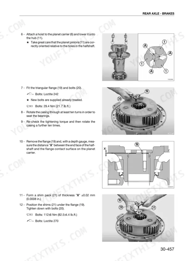
Fully. The overhaul chapters walk through engine and transmission separation, then the H-M-L unit, front and rear transmission casings, rear gearbox, shuttle assembly, PTO clutch, power shift cover, and the rear axle and brakes. Torque figures are printed where you need them, such as 490 Nm for wheel nuts and 122 Nm for crown wheel bolts. This is teardown-and-rebuild detail, not just theory. p. 772
Are wiring diagrams included, or just component descriptions?
Both. The electrical section is structured with indices, components, systems, planimetry, and the wiring diagrams with connector locations, so you can trace a circuit from the fusebox to the pin. There are also removal and refitting procedures for the ECUs, arm-rest control panel, steering column switch unit, instrument panel and the air conditioning components in the cab. p. 1017

Reviews
There are no reviews yet.