


Factory specifications for the Sperry New Holland 96 Rotary Hay Mower are detailed across 65 pages, covering the fully offset 8-foot dual-rotor cutter from initial assembly to a complete gearbox rebuild. The guide includes hydraulic schematics for the full lift circuit and a fault chart diagnosing blade clash, slip clutch failure, and drive line issues. Exploded views map out every assembly group from the main frame to the PTO. Step-by-step procedures walk through rotor removal, gearbox teardowns, and main cover replacement sequences. Set the slip clutch to 6,800-7,200 ins/lbs, torque gearbox mounting hardware to 180-200 ft./lbs., and check wheel bearing play after the first 50 acres. The file is bookmarked and keyword-searchable, so you can pull it up on a tablet and get back to cutting.
What's Inside This Sperry New Holland 96 Manual
| System | Pages | Key Topics |
|---|---|---|
| Specifications | 3 | Specifications Table, Optional Equipment, Chain Guard |
| Features | 4 | Fully Offset, 8ft. Cut, Torsion Bar Suspension, Moderate Power Requirement, Patented Quick Release Blade with 4 Cutting Edges, Blades, Height Adjustable Skids, Topping to 12" |
| Assembly | 6 | Check Shipping Damage While Removing Parts From Shipping Position, Check for Short Shipments and Owners Kit Complete, Locate and Attach Drawbar Tongue |
| Predelivery Service Checklist | 7 | Lubricate As per Owner's Manual, Check and Adjust As Required, Attach Mower to Tractor, Check Before Proceeding, Check |
| Delivery and Start-Up Checklist | 8 | Hitching, Hydraulics Operation, PTO Speed, Lubrication Points, Slip Clutch Adjustment, Rotor Timing |
| Setting Up Mower for Operation | 9-17 | Priming Hydraulics, Hitching Mower to Tractor, P.T.O. Speed, Tipping Bearing Adjustment, Mower Suspension, Torsion Bar Latch, Torsion Bar Adjustment, Height Control |
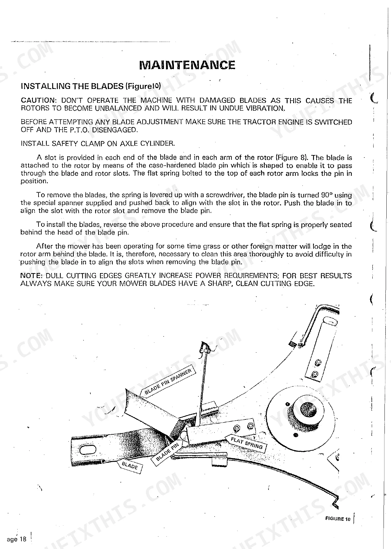
| Maintenance | 18-20 | Installing the Blades, Checking and Adjusting Slip Clutch, Timing Rotors Following Shearpin Breakage |
| Lubrication | 21 | Gearboxes |
| Notes | 22 | - |
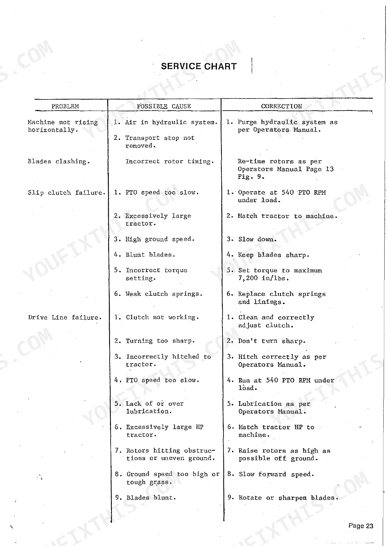
| Service Chart | 23-24 | Machine Not Rising Horizontally, Blades Clashing, Slip Clutch Failure, Drive Line Failure, Shearpin Failure, Flotation Too Heavy |
| Servicing Gearboxes | 25-33 | Rotor Gearbox Removal From Machine, Re-Assembly of Rotor Gearboxes, Installing and Timing Rotor Gearboxes |
| Servicing Tongue Jack Cylinder | 34-36 | Remove All External Fittings, Secure End Cap and Turn Cylinder Around Piston, Slightly Bend Tapered End of Circlip, Turn Cylinder Back Against and Under Circlip, Pull Circlip Free |
| Main Cover Replacement Procedure | 37 | Replace Main Cover, Replace All Hardware Loosely, Ensure Skids Are on a Level Surface, If Necessary Raise Front Right-Hand Skid, Tightening Sequence (First, Second, Third, Last) |
| Wheel Bearing Adjustment | 38 | Adjust After First 50 Acres, Thereafter Adjust Every 1, 000 Acres, Adjustment Procedure (Jack Wheel Off Ground, Check for Free-Play, Remove Bearings, Clean and Repack) |
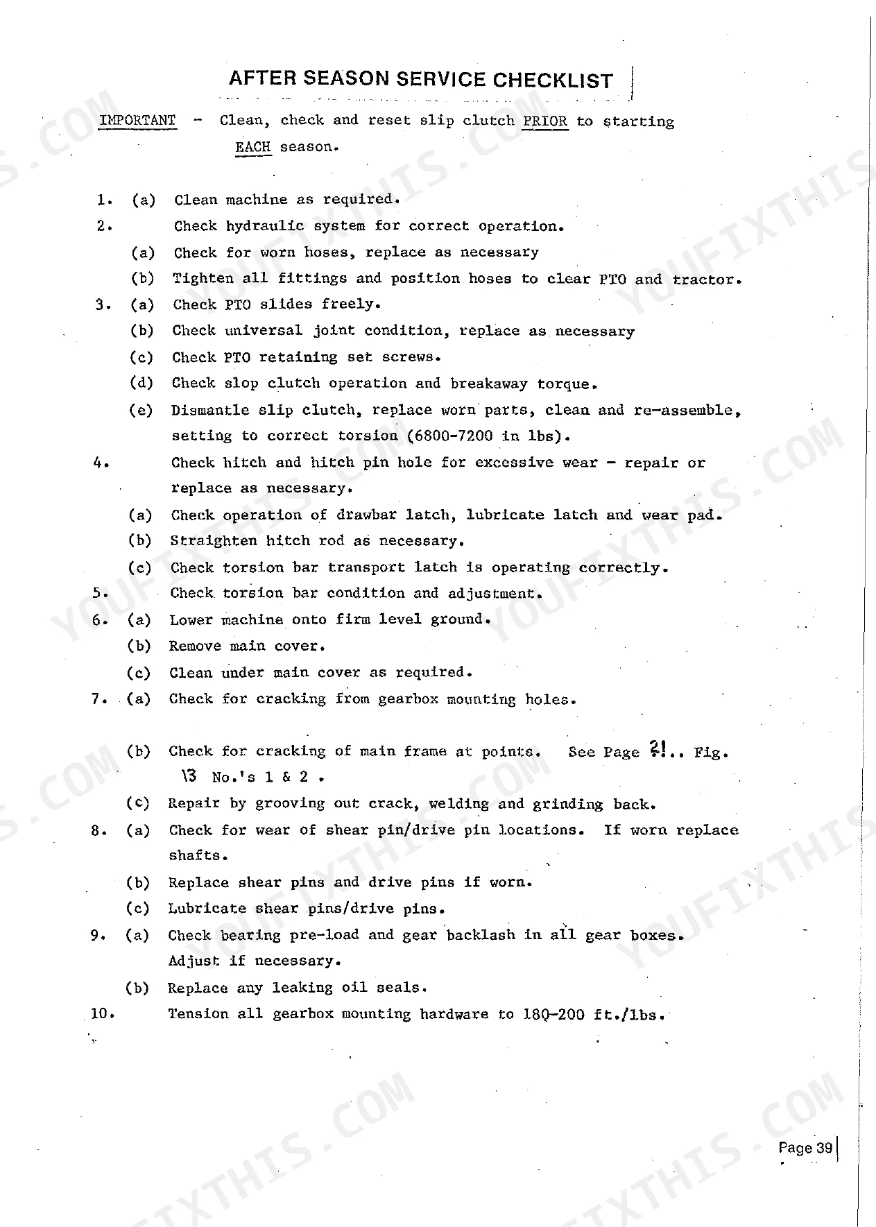
| After Season Service Checklist | 39-40 | Clean, Check and Reset Slip Clutch Prior to Starting Each Season, Clean Machine As Required, Check Hydraulic System for Correct Operation, Check PTO Slides Freely |
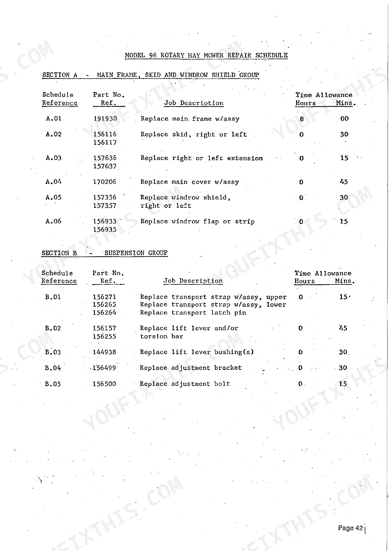
| Repair Schedule | 41-47 | Section a Main Frame, Skid and Windrow Shield Group, Section B Suspension Group, Section C Axle Group, Section D Gearbox, Rotor and Drive Shaft Group |
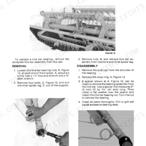
| Rotor Puller | 48 | Rotor Puller Fabrication, Rotor Removal, Re-Fitting the Rotor |
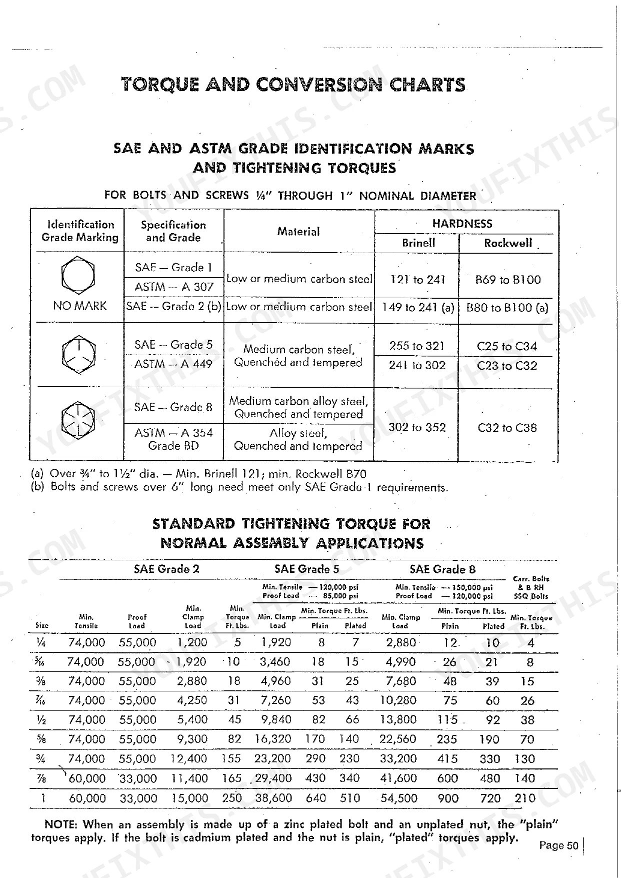
| General Information | 49-58 | Hardware Key, Metric Conversion Chart, Thread Sizes, Sae and Astm Grade Identification Marks and Tightening Torques, Standard Tightening Torque for Normal Assembly Applications |
| Service Bulletin | 59-65 | Model 96 Rotary Hay Mower P/N 190548 Drive Pin, Premature Failures of P/N 190548 Drive Pin |
Quick Reference Specifications
| Specification | Value | Page |
|---|---|---|
| Slip clutch torque setting | 6,800-7,200 ins/lbs | p. 19 |
| Drive pin replacement part number | No 190548 pin assembly | p. 19 |
| Drive shaft modification for drive pin | Ground Area Depth 1.5 mm Diameter 30 mm | p. 61 |
| Special Shear Pin part number | No 170543 | p. 20 |
| Special Shear Bolt part number | No 170674 | p. 32 |
| Input shaft oil seal part number (Main Drive Gearbox) | 28246 | p. 44 |
| Pinion shaft oil seal part number (Rotor Gearbox) | 156300 | p. 44 |
| Number of blades | 6 blades (3 per rotor) | p. 4 |
| Blade condition | ALWAYS MAKE SURE YOUR MOWER BLADES HAVE A SHARP, CLEAN CUTTING EDGE. | p. 18 |
| Rotor gearbox bearing pre-load (end cap) | 16-20 pounds pull | p. 29 |
| Rotor gearbox bearing pre-load (side plate) | 35-45 pounds pull total | p. 30 |
Sperry New Holland 96 Common Problems This Manual Covers
Slip clutch slips under load or needs constant readjustment after contamination
Disassemble the clutch and inspect discs for oil contamination or glazing, as both kill friction fast. Clean all surfaces, replace worn discs, and reassemble. Torque the adjustment springs to 6,800-7,200 ins/lbs (page 19). Verify the PTO runs at exactly 540 RPM. Low PTO speed is a listed cause of repeated slippage.
Manual Section: Maintenance p. 19Rotor gearbox runs hot, makes grinding noise, or leaves oil puddles under the mower
Stop immediately and check the oil level. Each rotor gearbox holds 1.7L of SAE 90 gear oil (page 21). If noise continues after topping up, pull the gearbox per page 25 and check bearing preload. The end cap should measure 16-20 pounds pull (page 29). Inspect and torque all pinion bearing housing studs, since loose hardware here is a confirmed failure trigger.
Manual Section: Servicing Gearboxes p. 29Shear pins or drive pin P/N 190548 breaking repeatedly during normal mowing conditions
Check hitch alignment and confirm the PTO runs at 540 RPM. Misalignment and foot-throttle use are primary causes in the service chart on page 23. Inspect the drive shaft bore for sharp burrs. The service bulletin on page 59 traces most P/N 190548 failures to burr damage. The corrective grind is 1.5 mm deep, 30 mm diameter (page 61).
Manual Section: Service Bulletin p. 59Rotors clash, cut unevenly, or vibrate badly after a shear pin replacement
Re-time the rotors immediately. Blades clashing means they are out of phase, confirmed in the service chart on page 23. Follow the timing procedure on page 20, then torque the rotor mounting nut to 400 ft lbs. Inspect all six blades. The quick-release design lets you rotate each to a fresh cutting edge without pulling the rotor.
Manual Section: Maintenance p. 18Machine won't rise horizontally or stays locked in transport position after delivery setup
Review the service chart on page 23 first. The shipping stop must be removed and the tongue jack cylinder fully extended before the machine can lift. Confirm tractor hydraulic pressure is at least 1,800 psi, as an underpowered tractor won't raise the unit. If still sluggish, work through the priming and setup sequence on page 9 from the start.
Manual Section: Service Chart p. 23Oil weeping from gearbox housings or drive shaft seal contact points after field use
Drain and remove the leaking gearbox per page 25. Replace the failed seal: main drive gearbox uses input shaft seal P/N 28246; rotor gearboxes use pinion shaft seal P/N 156300. Inspect shaft surfaces for wear grooves before fitting new seals. Refill each rotor gearbox to exactly 1.7L of SAE 90 gear oil per the lubrication chart on page 21.
Manual Section: Servicing Gearboxes p. 25Frequently Asked Questions
What are the torque specs for Sperry New Holland 96 bolts?
The manual provides a general torque chart for standard assembly applications on page 50, listing values for SAE Grade 2, 5, and 8 bolts across various sizes. For instance, a 3/8" SAE Grade 5 bolt (plain) requires 31 Ft. Lbs. Specific torque values are also provided for certain components, such as rotor gearbox mounting bolts at 180-200 ft./lbs. and rotor attaching nuts at 400 ft./lbs. p. 50
How to adjust torque on Sperry New Holland 96
To adjust the slip clutch torque, apply a measured force on a bar through the PTO yoke. The clutch should slip when a force of 6,800-7,200 ins/lbs is applied. Adjust the tension springs evenly and in small increments until the prescribed tension is achieved. p. 19
What are the replacement specifications for clutch discs?
Replacement clutch discs are identified by Part No. 170708 in the repair schedule. The manual instructs to dismantle the clutch, examine the discs, and replace them as required, especially if they are contaminated with grease or show wear. p. 19
What are the replacement specifications for drive pin assembly?
The replacement drive pin assembly is Part No. 190548. A service bulletin (9/80) advises to delete the thin washers from the kit and install thicker washer P/N 87364 under each roll pin (P/N 118327) during reinstallation. p. 19
What do I get after purchasing this Sperry New Holland 96 manual?
A 65-page Service Manual in searchable PDF format, available the moment you complete checkout. View on computer, tablet, or phone — no shipping wait.
Is this Sperry New Holland 96 Service Manual printable?
No restrictions at all. Print individual pages, full chapters, or the entire manual. The PDF is completely unlocked.
Are hydraulic system diagrams in this Sperry New Holland 96 Service Manual?
Full hydraulic system diagrams are included, covering circuits, valve locations, and hydraulic component specs for the Sperry New Holland 96.

Reviews
There are no reviews yet.