


Part of the Yanmar Parts Manuals.
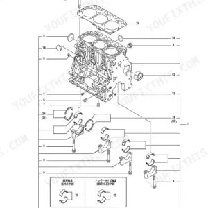
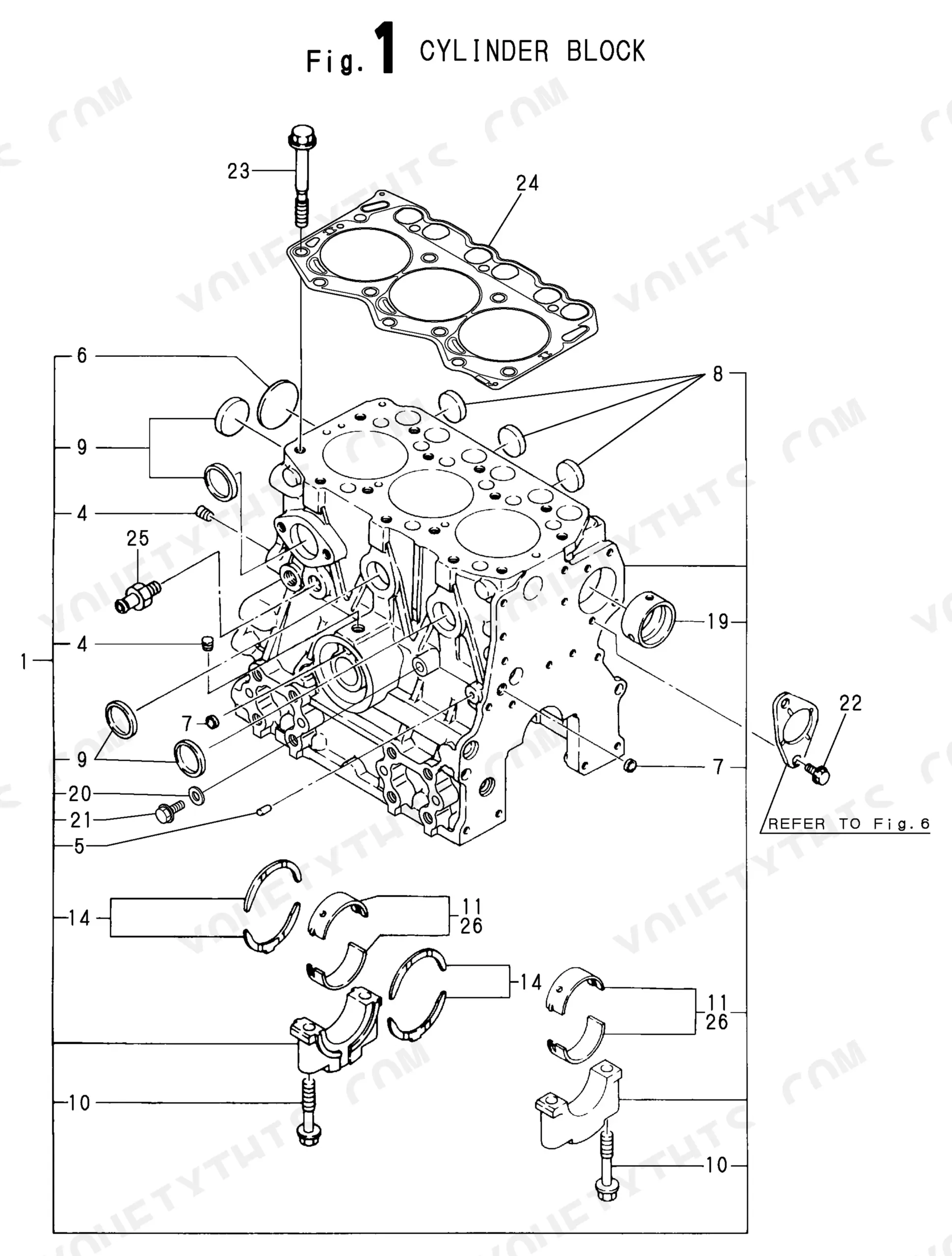
Hunting down the right part number for your Yanmar 4TN100E-GB1, 4TN100TE-GB1, or 4T112TLE-GB1 engine? This 100-page parts catalog (OEM #Y00S2993) is the factory reference that maps every component from cylinder block to generator end. Inside: exploded assembly views with OEM part numbers covering the full engine build, including cylinder block, gear housing, oil sump, cylinder head, turbocharger, camshaft and driving gear, crankshaft and piston, and the complete fuel system from injection pump through fuel filter and separator. Electrical coverage runs from starting motor through generator, instrument panels, and gasket sets for both the block and head. Component dimensions are called out directly on the diagrams: the camshaft key runs 7x14mm, the crankshaft seal 95x115x10mm. No more chasing part numbers off a worn tag. Bookmarked by system; open on any device and find what you need in seconds.
What's Inside This Yanmar 4TN100E-GB1 / YEG45-90 Series Parts Manual
| System | Pages | Key Topics |
|---|---|---|
| Fuel System | Air Cleaner, Fuel Injection Pump, Governor, Fuel Injection Line, Fuel Line, Engine Stop Device, Suction Manifold & Air Cleaner, Fuel Feed Pump, Fuel Filter & Separator | |
| Cooling System | Cooling Water System | |
| Engine | Cylinder Block, Cylinder Head, Suction & Exhaust Manifold, Camshaft & Driving Gear, Crankshaft & Piston, Oil Cooler, Gasket Set, Gasket Set&tool, Exhaust Manifold & Silencer, Lub. Oil Cooler | |
| Hydraulics & 3-Point Hitch | Feed Pump | |
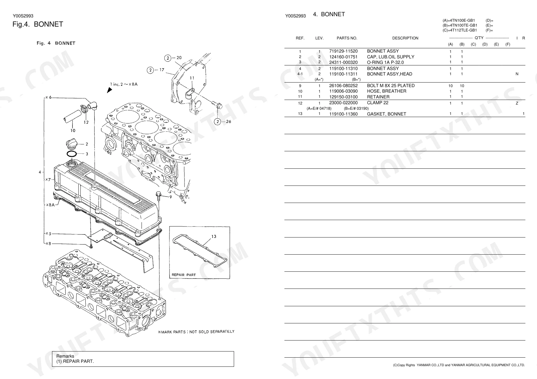
| Body & Operator Station | Bonnet, Common Bed Frame | |
| Other Components | Gear Housing, Oil Sump & Lub. Oil System, Turbocharger, Separator, Starting Motor, Generator, Electric Part, Lub. Oil Line, Instrument Panel |
Quick Reference Specifications
| Specification | Value | Page |
|---|---|---|
| Key Dimension (Camshaft) | 7x14mm | p. 11 |
| Seal Dimension (Crankshaft) | 95x115x10mm | p. 12 |
Yanmar 4TN100E-GB1 / YEG45-90 Series Common Problems This Manual Covers
Piston ring set and crankshaft rear seal part numbers needed after internal cylinder scoring diagnosis
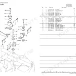
Open the crankshaft assembly diagram on page 12. The Piston W/RINGS line item lists the ring set part number, and the crankshaft rear seal is dimensioned at 95x115x10mm on the same page. Record the connecting rod bearing part numbers at the same time. Verify all items against your serial number range before placing the order.
Manual Section: Crankshaft Assy p. 12Camshaft tappets, push rods, and timing key part numbers hard to match to correct engine variant
Open the camshaft assembly diagram on page 11. The camshaft key is listed as 7x14mm on the parts list; use that to confirm you are on the correct diagram before recording tappet and push rod part numbers. For turbocharged variants, also cross-reference turbocharger shaft and journal bearing part numbers on pages 58-60.
Manual Section: Camshaft Assy p. 11Intake manifold heater element part number unclear for cold-start no-run complaint
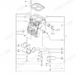
Open the intake manifold exploded view on page 7. The Heater line item is included within the Manifold Assy, Suc. parts list on that page. Record the heater part number and its mounting hardware from the same diagram. Pull the intake manifold gasket set on pages 31-32 to order the full seal kit at the same time.
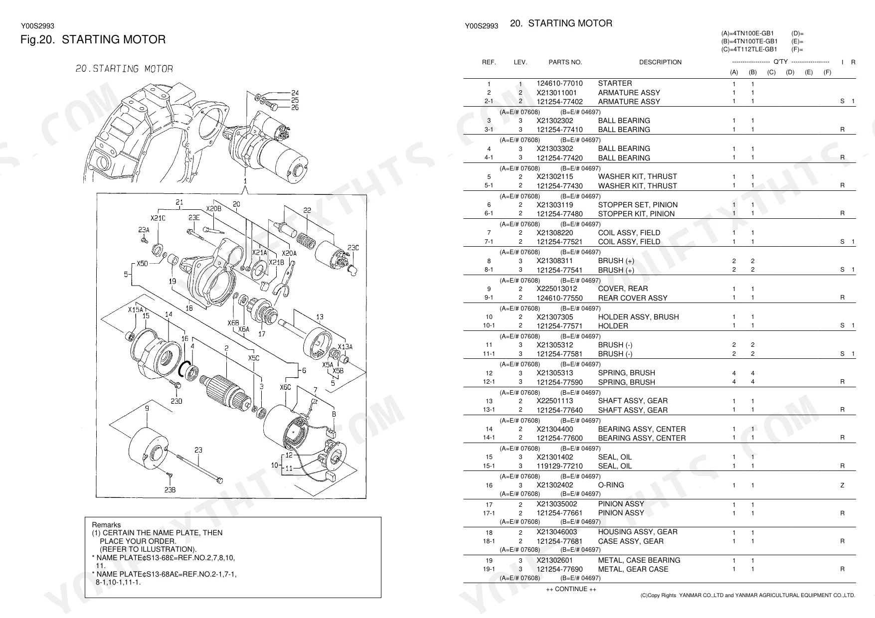
Manual Section: Manifold Assy, Suc. p. 7Starter motor armature, brush assembly, and pinion part numbers needed for no-crank teardown
Open the starter motor exploded view on pages 26-27. Locate the Armature Assy, Field Coil, and Brush line items and record each part number. The Ball Bearing and Pinion are listed separately on the same pages. For alternator rotor, stator, and voltage regulator part numbers, cross-reference the generator diagram on page 28.
Manual Section: Starter p. 26Frequently Asked Questions
What are the replacement specifications for Fuel filter?
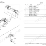
For replacement, the manual lists the fuel filter element with part numbers 42430-550060 (Ref 4) or 120324-55760 (Ref 4-1). These components are located in the "18. SEPARATOR" section of the manual. p. 24
What are the replacement specifications for Fuel line?
The manual provides several fuel line components for replacement, such as "JOINT 12, PIPE" (Part No. 101304-59020, Ref 1) and "FUEL OIL PIPE" (Part No. 105025-59530, Ref 7). Additional fuel injection pipes are also detailed within the "17. FUEL LINE" section. p. 22
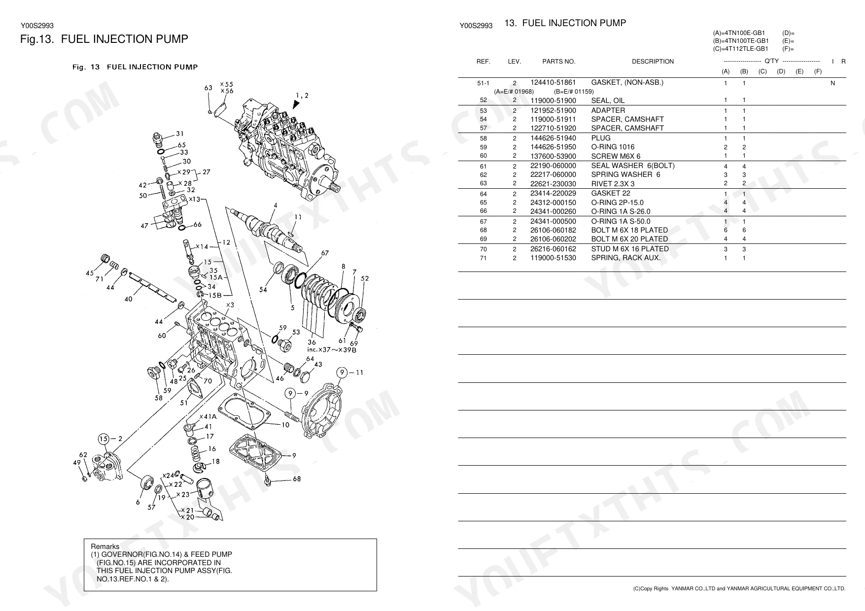
How do you fix yanmar 4TN100E-GB1 injection pump plunger and barrel assembly part numbers needed, cranks but won't fire?
Open the injection pump exploded view on page 16, covering the complete Pump W/GOV.& F.PUMP assembly. Locate the Plunger W/BARREL and Tappet Assy line items and record their part numbers. Check pages 31-32 for the matching fuel system gasket set and O-rings. Cross-reference your serial number range in the parts index before ordering to confirm fitment. p. 16
How do you fix fuel separator element, O-ring, and inline filter part numbers needed for complete fuel system cleaning?
Check page 22 for the fuel oil pipe and inline fuel filter part numbers. The separator element, O-ring, and spring are listed separately on page 24. Order both sets together; also pull the complete gasket set on pages 31-32 to cover seals in the separator housing and filter head at the same time. p. 24
What format is this manual in?
A 100-page Parts Catalog in searchable PDF format, available the moment you complete checkout. View on computer, tablet, or phone, with no shipping wait.
Is this Yanmar 4TN100E-GB1 & variants Parts Catalog printable?
Yes. The PDF has no DRM restrictions, so print any page or section you need for your shop. Works with any standard printer.

Reviews
There are no reviews yet.