


Part of the Yanmar Parts Manuals.
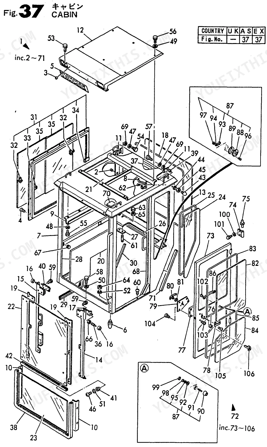
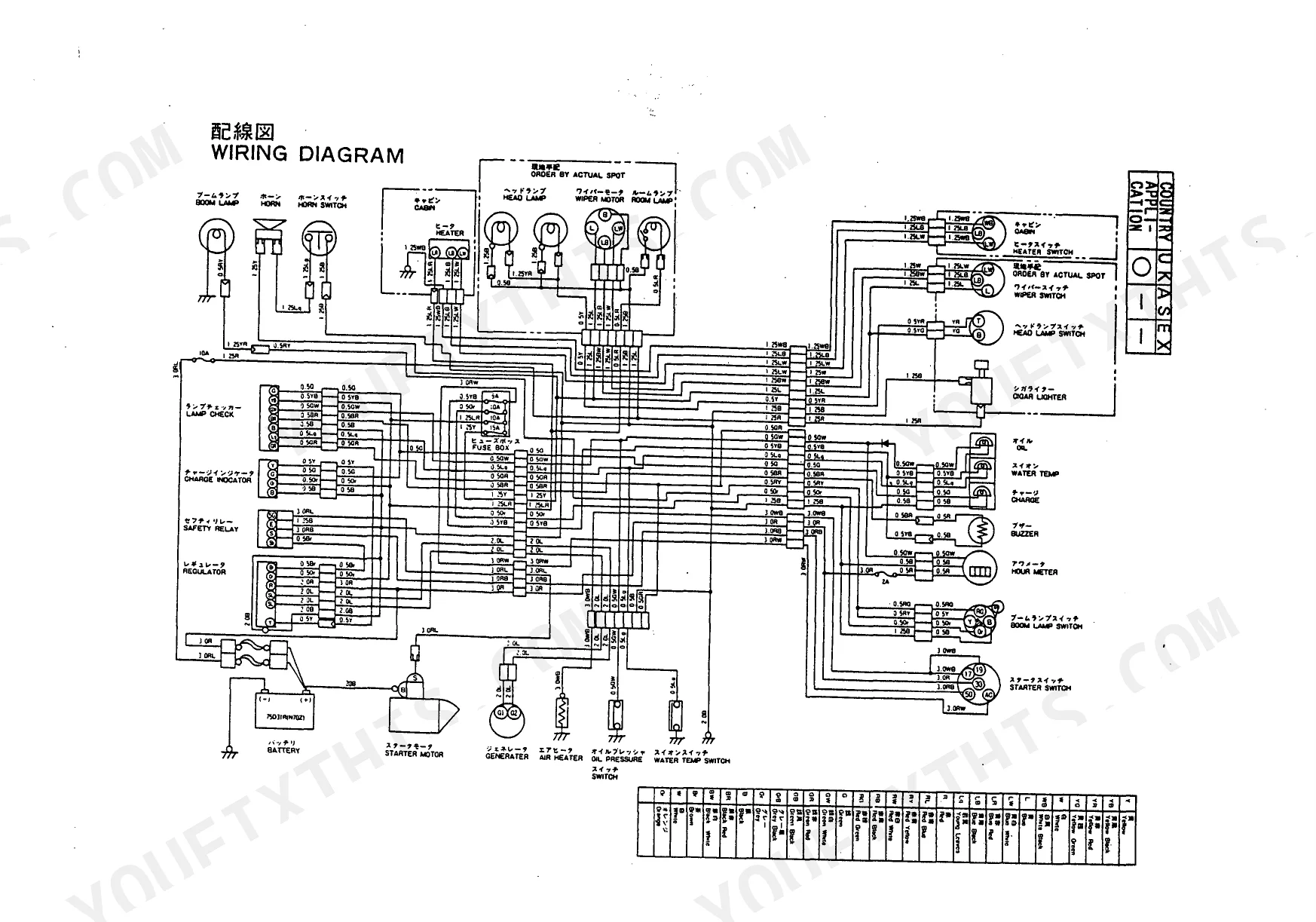
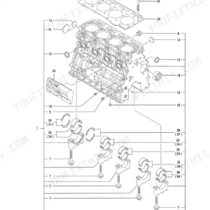
All 150 pages of this Parts Catalog lock onto one machine family. Inside, you get fully exploded views and part numbers for every system on the machine: boom and bucket linkage, all five cylinders (arm, swing, boom, blade, bucket), turning motor, travel motor, swivel joint, control valve, track frame, and crawler assembly. Wiring diagrams cover the complete electrical harness, fuses, relays, and indicator panel; hydraulic circuit maps trace every line from the pump and oil tank through the piping, 3rd valve control, and individual actuators. OEM part number 000Y00S3010.
What's Inside This Yanmar B22-P / PR / C / CR Series Parts Manual
| System | Pages |
|---|---|
| ROPS | - |
| Electric Part | - |
| Air Cleaner & Silencer | - |
| Engine Mount & Radiator | - |
| Fuel Tank & Fuel Line | - |
| Bonnet | - |
| Hyd. Oil Pump & Joint | - |
| Hyd. Oil Tank | - |
| Link Stand | - |
| Control Equipment | - |
| Operation Lever Stopper | - |
| Arm Cylinder | - |
| Swing Cylinder | - |
| Greasing | - |
| Work Lamp | - |
| Boom Cylinder | - |
| Blade Cylinder | - |
| Blade | - |
| Hyd. Oil Piping | - |
| 3rd Valve Control | - |
| 3rd Valve Piping | - |
| Boom & Bucket | - |
| Bucket Cylinder | - |
| Turning Frame | - |
| Turning Driving Gears | - |
| Turning Motor | - |
| Swivel Joint | - |
| Control Valve | - |
| Accelerator | - |
| Battery | - |
| Seat & Step | - |
| Track Roller | - |
| Track Frame & Idler | - |
| Crawler (270) | - |
Quick Reference Specifications
| Specification | Value | Page |
|---|---|---|
| B22-P(R) / B22-C(R) | ||
| 3TN75L-RBVM / 3TN75L-RB | ||
| Parts Catalog | ||
| 150 | ||
| 000Y00S3010 | ||
| 172141-73100 | ||
| 172141-29110 | ||
| See page 107 |
Yanmar B22-P / PR / C / CR Series Common Problems This Manual Covers
Yanmar B22 crawler track link, bush, and shoe 270 part numbers needed after undercarriage damage
Open the Crawler (270) section and go to the exploded view on page 40. The track assembly breaks into discrete line items: Link Assy, Bush, Pin, and Shoe 270. Confirm the shoe width is 270mm before ordering - the rubber and steel shoe variants are separate SKUs in the parts list. Cross-reference the parts index using your serial number prefix to confirm correct link pitch for your build date.
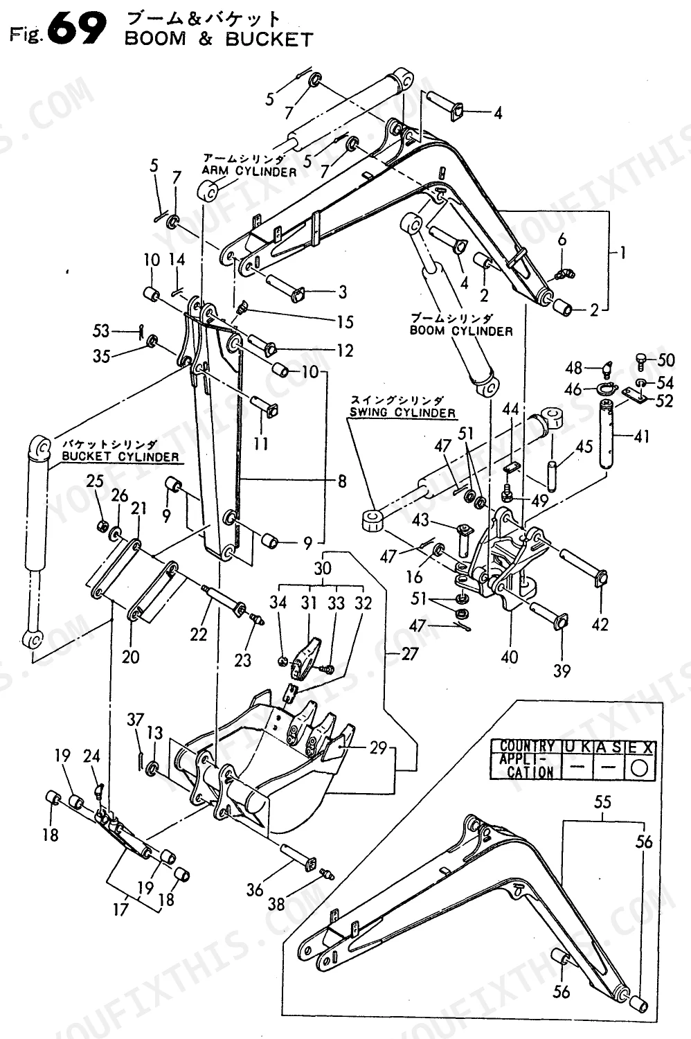
Manual Section: Crawler (270) p. 40Seal set part number unclear when ordering hydraulic cylinder components for arm, boom, or bucket
Go to the Hydraulic Parts Diagram on page 107. Each cylinder lists its Seal Set as a single kit line item - do not attempt to source individual seals unless the exploded view explicitly breaks them out separately. The Arm Cylinder, Boom Cylinder, and Bucket Cylinder each carry a distinct Seal Set part number. Identify your specific cylinder by callout position in the diagram, then verify against the serial number range in the index header before ordering.
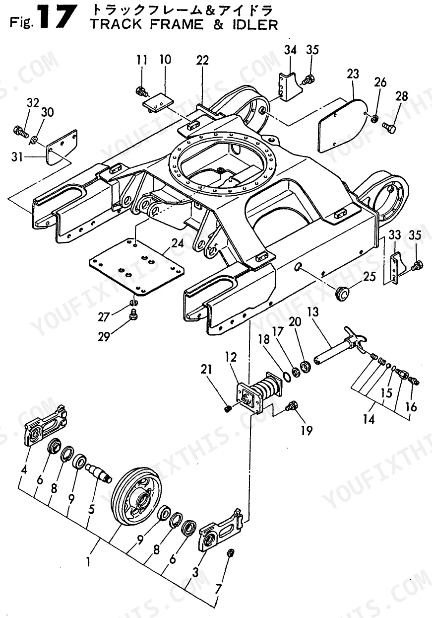
Manual Section: Arm Cylinder p. 107Track frame idler seal and bearing identification when ordering replacement components for a leaking idler
Reference the Track Frame & Idler exploded view on page 40. The idler shaft seal is listed as Seal 357220 in the parts index - use that designation when ordering. The Idler 280 Assy is a 280mm diameter unit; confirm your idler matches that dimension before sourcing the ball bearing and piston listed alongside it. If the idler has significant hours, order the ball bearing at the same time as the seal to avoid a second disassembly.
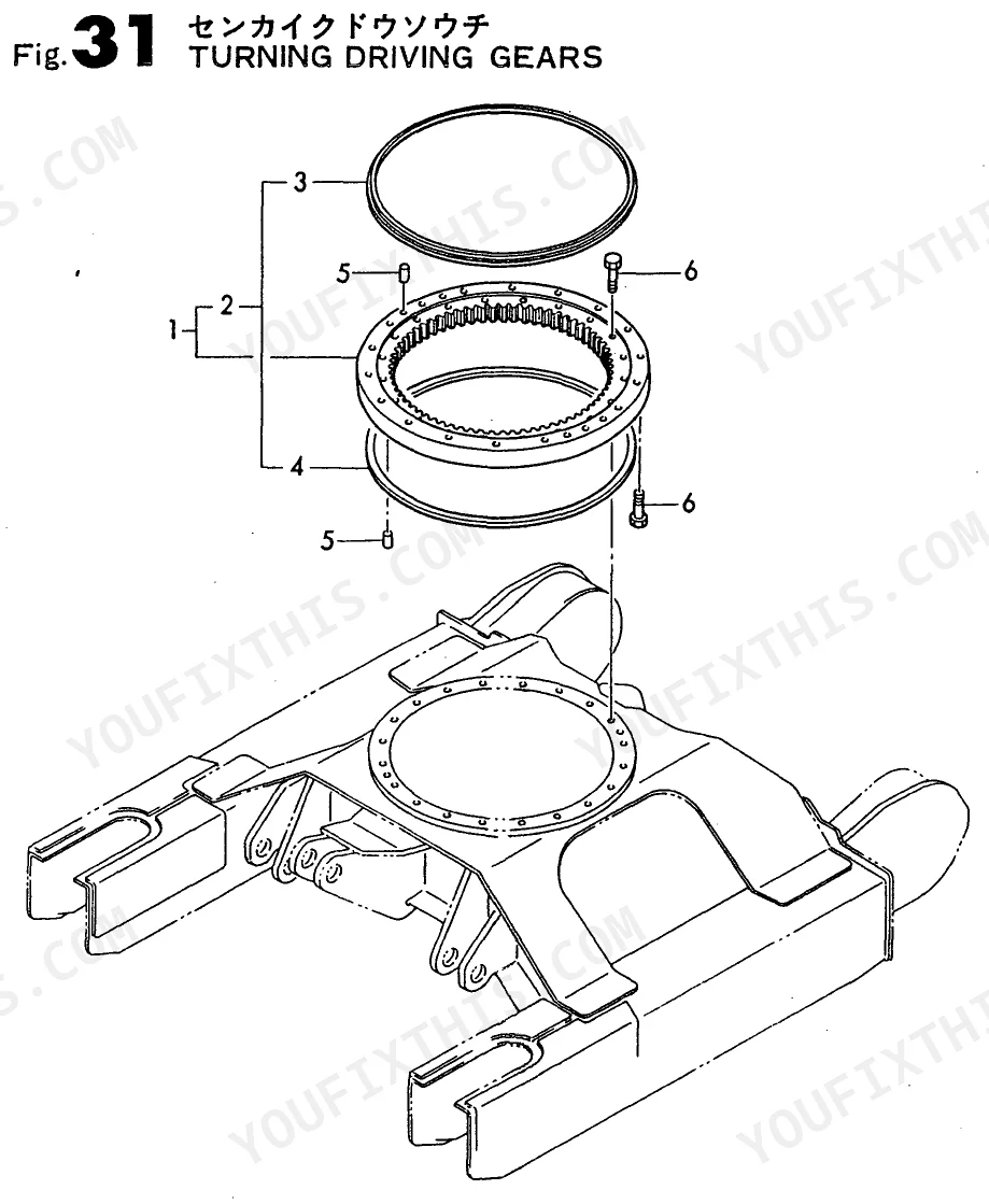
Manual Section: Track Frame & Idler p. 40Turning motor planetary gear and bearing part numbers for swing drive component replacement
Locate the Drivetrain Parts Diagram on page 68. The Turning Motor parts list sequences components as: Motor Assy, Drive Seal, Floating Bearing, Angular Bearing, and Planetary Gear (B). Identify which bearing is worn - floating and angular types are not interchangeable and carry separate part numbers. Also check the Turning Driving Gears section for the upper and lower seal line items if the swing bearing housing shows any weeping at the frame interface.
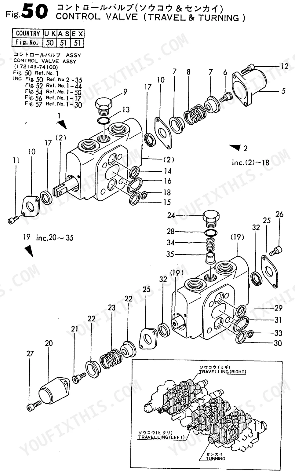
Manual Section: Turning Motor p. 68Control valve seat, spring, and plug part identification when sourcing internal valve body components
Find the Control Valve section in the Hydraulic Parts Diagram on page 107. The parts list itemizes: Valve Assy, Body Assy, Cover, Seat, Spring, and Plug individually. If multiple internal components are worn, price the complete Valve Assy against the sum of individual parts - ordering the assembly is often faster and avoids mismatched component generations. Confirm model variant (B22, B22-P(R), or B22-C(R)) via the serial number prefix in the index before finalizing the order.
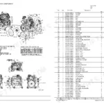
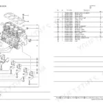
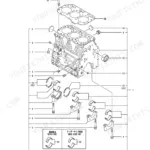
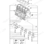
Manual Section: Control Valve p. 107Engine mount bracket, vibration absorber, and radiator hose part identification after mount failure or hose damage
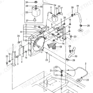
Open the Engine Parts Diagram on page 19. The Engine Mount & Radiator section lists Absorber, Stopper, Bracket, Mount, Radiator, and Hose as individual line items. Match each hose to its callout position in the exploded view - upper and lower radiator connections are separate part numbers. The vibration absorber and stopper are a paired set in the diagram; if the mount bracket shows cracking or shift, order both the absorber and stopper together to restore correct engine positioning.
Manual Section: Engine Mount & Radiator p. 19Frequently Asked Questions
How do I check hydraulic oil level?
The manual identifies a "GAUGE, OIL LEVEL" (part number 172122-75600) as a component of the hydraulic oil tank. However, it does not provide specific instructions on how to check the hydraulic oil level or what the correct level should be. p. 122
What are the replacement specifications for Hydraulic pump?
The replacement specification for the hydraulic oil pump assembly is part number 172141-73100. This part is listed under the "HYD. OIL PUMP & JOINT" section. p. 98
What are the replacement specifications for Drive sprocket bearing?
The replacement specification for the sprocket is part number 172141-29110, and the bearing associated with the truck roller assembly is part number 933111-73800. These parts are listed in the "TRUCK ROLLER" section. p. 37
How do you fix crawler track link, bush, and shoe 270 part numbers needed after undercarriage damage?
Open the Crawler (270) section and go to the exploded view on page 40. The track assembly breaks into discrete line items: Link Assy, Bush, Pin, and Shoe 270. Confirm the shoe width is 270mm before ordering — the rubber and steel shoe variants are separate SKUs in the parts list. Cross-reference the parts index using your serial number prefix to confirm correct link pitch for your build date. p. 40
Is this Parts Catalog a digital download?
This is a 150-page searchable PDF ready for immediate download. Works on any device, so pull it up on your phone while you're under the hood. No shipping, no waiting.
Can I print this manual?
Yes. The PDF has no DRM restrictions, so print any page or section you need for your shop. Works with any standard printer.
Are there hydraulic schematics in this manual?
Yes, this Parts Catalog includes a hydraulic system diagram.
Reviews
There are no reviews yet.