


Part of the Yanmar Parts Manuals.
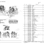
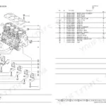
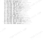
All 43 pages of this Yanmar TB135 Parts Catalog focus on one job: finding the exact part number for your 3TNV88-QTB2 engine before you waste an afternoon chasing the wrong component. Inside, you get exploded views and numbered parts lists across 18 figures covering every major assembly - cylinder block, gear housing, flywheel housing, crankshaft and piston, fuel injection pump with inner parts and governor, starter motor, alternator, and the complete gasket set. Each figure pairs a detailed exploded diagram with a cross-referenced parts table so you can identify a component visually and pull its Yanmar part number in one step. Your cooling system section calls out the V-belt size split by serial number: A37 before S/N 13519312, A37.5 from that point forward - the kind of detail that prevents a wrong-size order. Your machine is down; stop guessing at part numbers. Bookmarked and searchable, this PDF lets you jump straight to any assembly by keyword or section.
What's Inside This Yanmar TB135 3TNV88-QTB2, TB135, 3TNV88-QTB2 Parts Manual
| System | Pages | Key Topics |
|---|---|---|
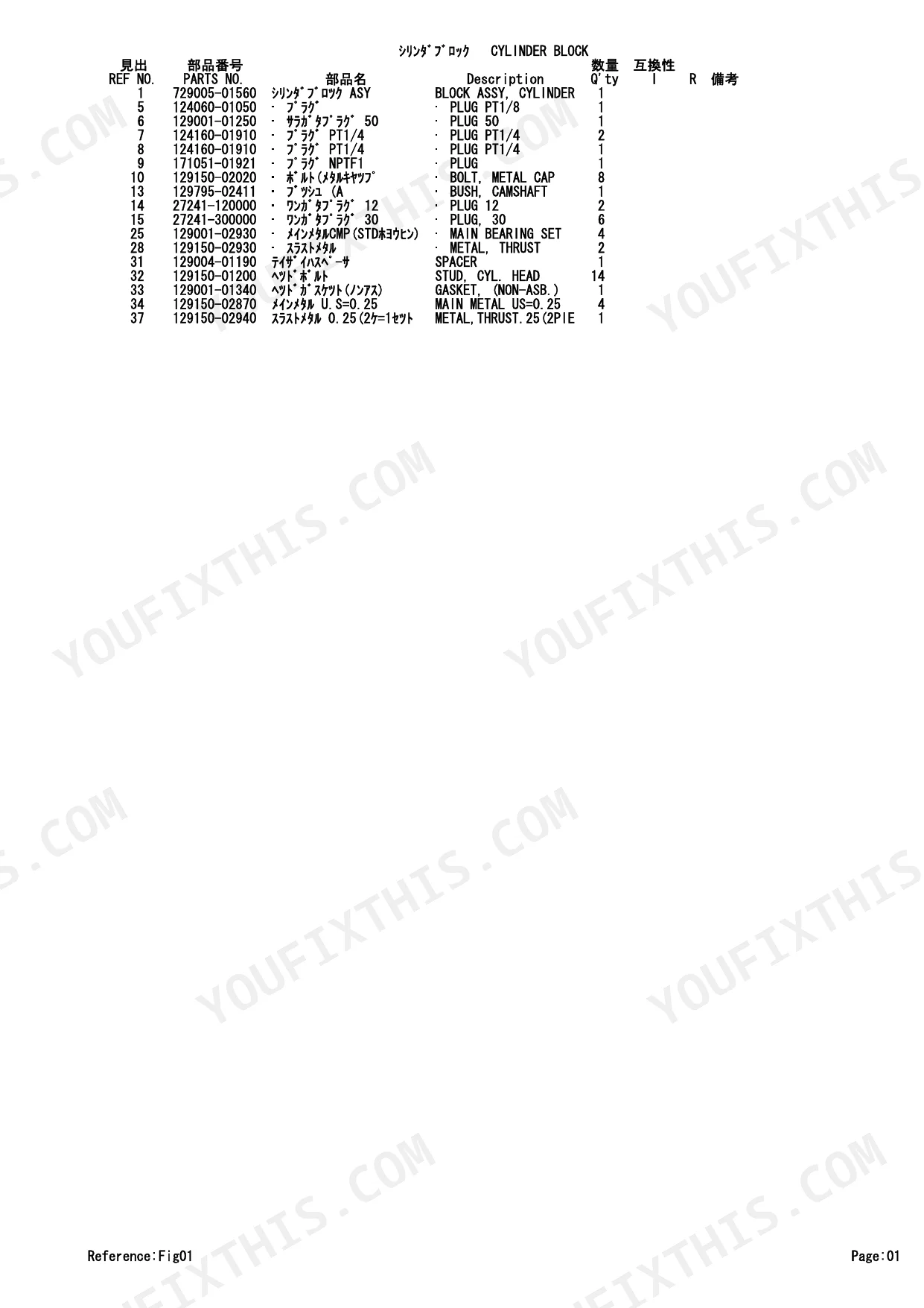
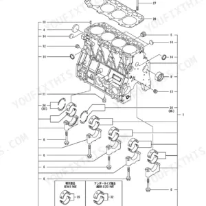
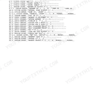
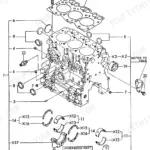
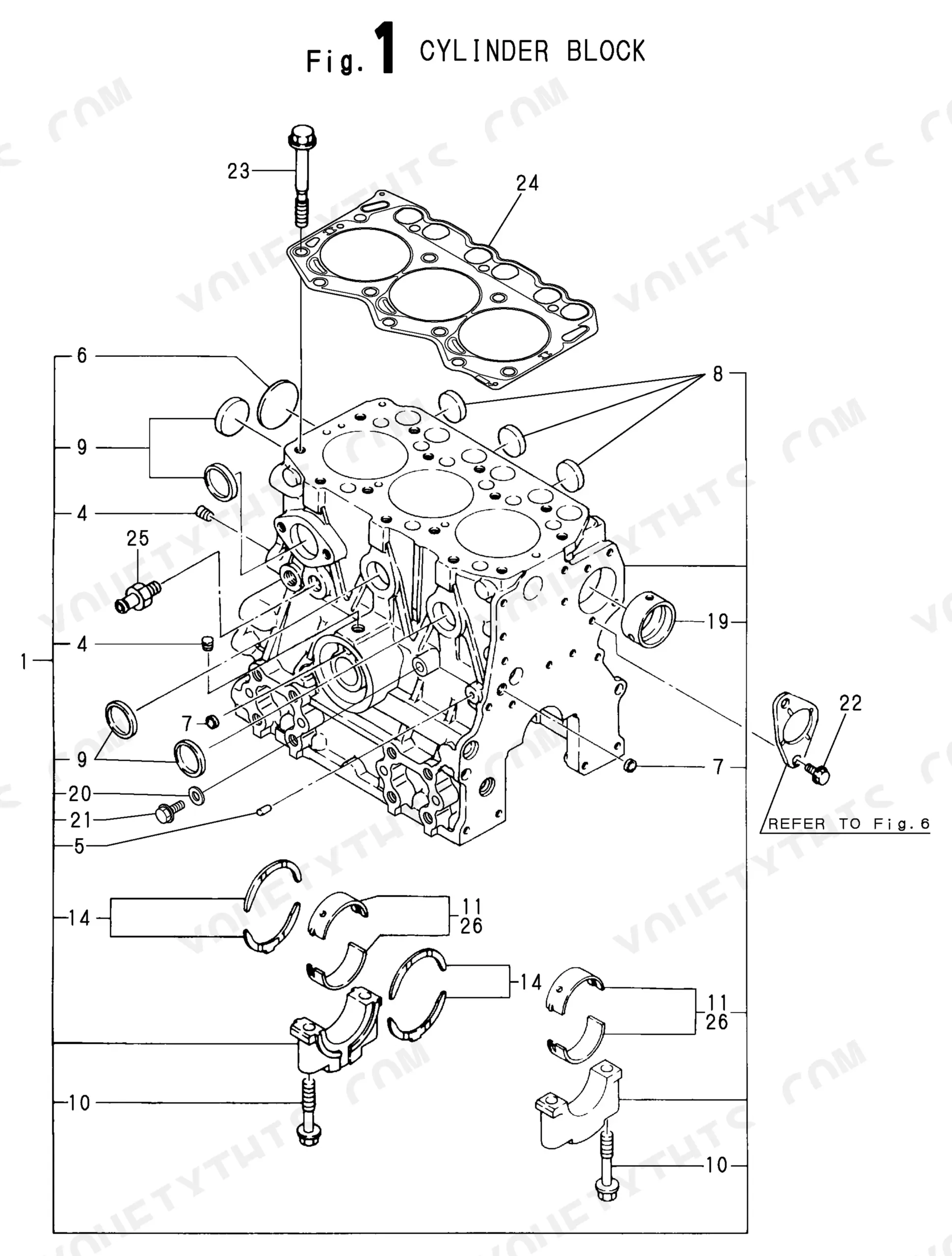
| Cylinder Block | 5-6 | Cylinder Block Assy, Camshaft Bush, Main Bearing Set, Thrust Metal, Spacer, Gasket, Main Metal |
| Gear Housing | 7-8 | Gear Housing Assy, Plug Pt, Oil Seal, Pump Cover Assy, Lub. Oil Pump Cover, Relief Valve, Spring, Gear Case Frange |
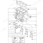
| Flywheel Housing & Oil Sump | 9-10 | Flywheel Housing, Flywheel Cover Cap, Oil Sump Spacer, Lub. Oil Sump Assy, Oil Seal Case Assy, Oil Seal, Liquid Gasket |
| Cylinder Head & Bonnet | 11-12 | Engine Lifter, Rocker Shaft Assy, Rocker Arm Shaft, Rocker Arm Support, Spring, Rocker Kit Arm Assy, Valve Cap, Cylinder Head Assy |
| Suction Manifold & Air Cleaner | 13-14 | Breather Pipe, Int Manifold Assy, Breather Joint, Pk Gasket, Air Heater, Air Heater Gasket, Bend, Inlet Silencer |
| Exhaust Manifold & Silencer | 15-16 | Exhaust Manifold, Exhaust Manifold Pk Gasket, Silencer Pk Gasket, Silencer, Silencer Pipe |
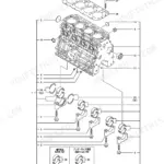
| Camshaft & Driving Gear | 17-18 | Tappet, Push Rod, Camshaft Assy, Thrust Metal, Camshaft D30 Gear, Idle Gear Shaft, Idle Gear Assy, Idle Gear Bush |
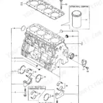
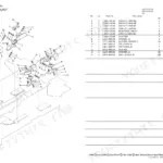
| Crankshaft & Piston | 19-20 | Crankshaft Assy, Crankshaft Gear, Crankshaft V D110 V-Pulley, Flywheel Assy, Ring Gear, Piston Assy, Piston Ring Set, Connecting Rod Assy |
| Lub.Oil System | 21-22 | Lub. Oil Dipstick, Dipstick Guide, Pk Gasket, Oil Inlet Lo Pipe Assy, Filter Bracket Assy, Filter Bracket, Filter 80X80L, R02 Joint |
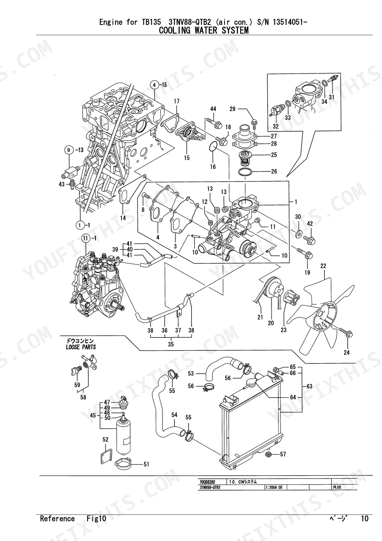
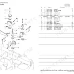
| Cooling Water System | 23-24 | Water Cw Pump Assy, Pk Gasket, Plate, Cw-T Joint, Joint, Cooling Water Pump V V-Pulley, V V-Belt, Fan |
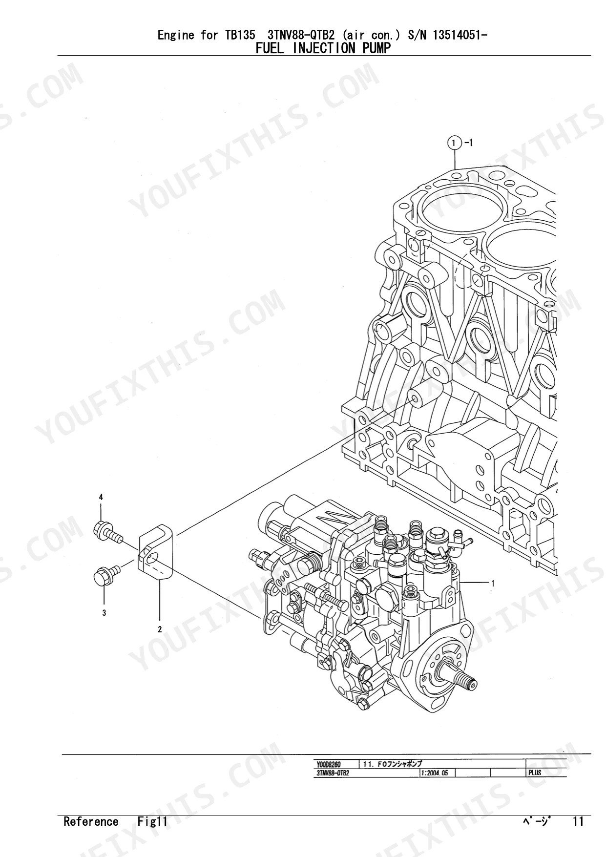
| Fuel Injection Pump | 25-26 | Injection Pump Assy, Pump Bracket, Bolt |
| Fuel Injection Pump (Inner Parts) | 27-28 | Fuel Injection Foassy Pump Assy, Joint, Stopper, Dilevery Valve Assy, Sp Spring, Delivery Holder, Cooling Water Joint, Lifter |
| Governor (Inner Parts) | 29-30 | Case Pk Packing, Pk Packing, Sp Spring, Regulator Lever, Shaft Retainer, Stop Solenoid, Case Cover |
| Fuel Injection Valve | 31-32 | Fo Assy Fuel Injector, Nozzle, Nozzle Holder Assy, Nozzle Spring, Nozzle Spring Seat, Stop Plate, Shim Pack, Retainer |
| Fuel Line | 33-34 | Filter Bracket, Fuel Fo Filter, Fuel Fo-T D13 .5XL220 Pipe, Pipe Protector, Fuel Oil Fo-T Pipe, Fuel Fo Pipe, Tube, Fuel Oil Fo Pipe |
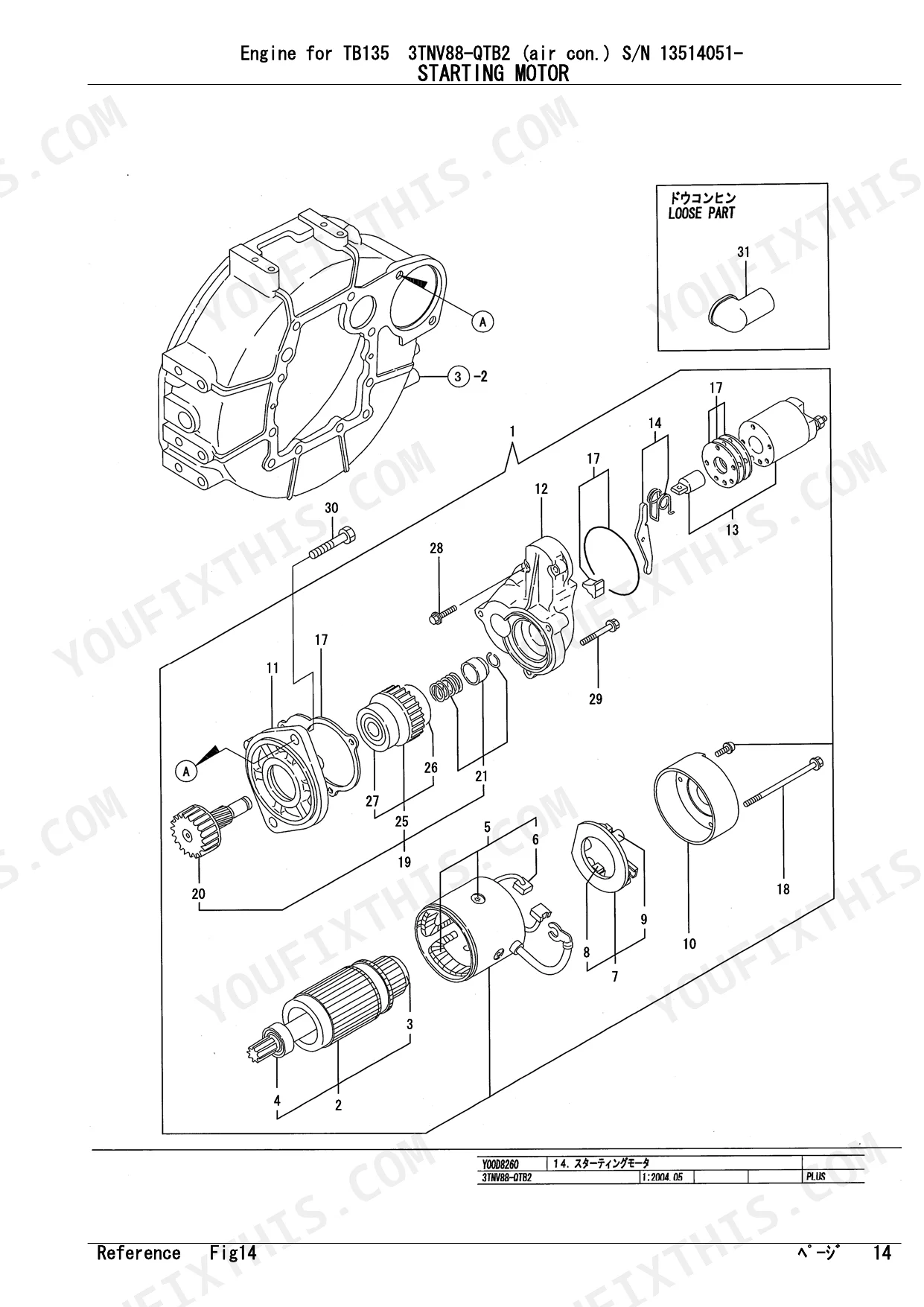
| Starting Motor | 35-36 | Armatuer, Bearing, Field Coil Assy, Brush, Brush Holder Assy, Start Spring Brush, Rear Cover |
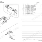
| Generator | 37-38 | Alternator, Rotor Assy, Ball Bearing, Bearing Cover, Drive Flame Assy, Drive, Plate, Bolt, Stud, Rear Flame Assy, Rear Assy |
| Gasket Set | 39-43 | Valve Stem Seal, Nozzle Protector, Nozzle Seat, Bonnet Gasket, Pk Gasket, Exhaust Manifold Pk Gasket, Silencer Pk Gasket |
Quick Reference Specifications
| Specification | Value | Page |
|---|---|---|
| Alternator output | 40A | p. 38 |
| Radiator Cap Pressure | 0.9 kgf/cm^2 | p. 24 |
| V-Belt Size (before S/N 13519312) | A37 | p. 24 |
| V-Belt Size (from S/N 13519312) | A37.5 | p. 24 |
Yanmar TB135 3TNV88-QTB2, TB135, 3TNV88-QTB2 Common Problems This Manual Covers
Can't identify correct alternator part number or output spec for charging circuit diagnosis
Turn to the Generator section on page 37. The exploded view covers the alternator, rotor assembly, ball bearing, regulator assembly, adjuster, and belt. The alternator output is rated at 40A (page 38) — use this to verify any replacement unit matches spec. The belt adjuster components are also listed there if the charging problem traces back to a slipping belt.
Manual Section: Generator p. 37Glow plug or stop solenoid part number needed for no-start electrical fault
Check the Governor (Inner Parts) section on page 29 for the stop solenoid and idle limit components. For glow plugs, go to the Suction Manifold & Air Cleaner section on page 13 where the air heater is listed alongside intake manifold parts. Confirm part numbers against the table on the facing page before ordering, as the air heater assembly and individual heater element may have separate line items.
Manual Section: Governor (Inner Parts) p. 29Need correct fuel filter and separator part numbers for fuel system service
Open the Fuel Line section on page 33. The parts list covers the fuel filter, fuel pump, separator assembly, and all fuel pipe runs. Cross-reference with the Fuel Injection Pump diagram on page 25 to confirm the upstream filter bracket and mounting hardware part numbers. Order both the filter element and the separator as separate line items — they are listed independently in the table.
Manual Section: Fuel Line p. 33Turbocharger oil feed seal kit part numbers missing from engine rebuild parts list
Start with the Lub. Oil System on page 21. The oil inlet pipe assembly, filter, and cooler inlet components are listed there. For gasket and seal kits covering the full engine, check the Gasket Set index on page 41, which organizes O-rings, valve stem seals, and nozzle protectors by system. If turbocharger-specific seals are not shown in these sections, note that the catalog may not list turbo sub-components separately — cross-reference with a Yanmar dealer using the engine serial number to identify the correct oil feed seal kit.
Manual Section: Lub.Oil System p. 21Frequently Asked Questions
What are the replacement specifications for Head gasket?
The manual identifies the head gasket as "GASKET, (NON-ASB.)" with part number 129001-01340. This indicates it is a non-asbestos type gasket. One unit is required for replacement. p. 6
What are the replacement specifications for Water pump?
The water pump is listed as "PUMP ASSY, WATER" with part number 129004-42001. This part is supplied as an assembly, and one unit is needed for replacement. p. 24
How do you fix yanmar TB135 head gasket part number needed for 3TNV88-QTB2 engine rebuild after overheating?
Open the Cylinder Head & Bonnet exploded view starting on page 11. The head gasket is listed in the parts number table on page 12. Cross-reference the Gasket Set section starting on page 39; the index on page 41 groups all gasket and seal components by subsystem, which helps confirm you have the complete set for a head job. Verify your serial number range before ordering. p. 11
How do you fix water pump assembly part number unclear, can't confirm which coolant hose connects to radiator?
Check the Cooling Water System exploded view on page 23. The water pump assembly, V-belt, fan, thermostat, and radiator assembly are all itemized there. For the TB135 3TNV88-QTB2, the radiator cap is rated at 0.9 kgf/cm² (page 24) — confirm the replacement cap matches that spec. Cross-reference hose routing in the same diagram to identify the correct inlet and outlet hose part numbers. p. 23
What format is this manual in?
A 43-page Parts Catalog in searchable PDF format, available the moment you complete checkout. View on computer, tablet, or phone, with no shipping wait.
Can I print just the pages I need from this Yanmar TB135 3TNV88-QTB2 manual?
Yes, print as many copies as you want, and there are no restrictions. Many mechanics print the section they need and bring it to the shop floor.
Reviews
There are no reviews yet.