


Want a Kubota B2650 workshop manual PDF that goes as deep as the factory techs do? This 539-page volume (OEM #9Y111-09820) covers the B2050, B2350, B2650, and B3150 end to end, from the diesel engine to the cabin air conditioning. It carries full wiring diagrams for both ROPS and cabin models, 27 pages of hydraulic schematics mapping the HST pump and motor circuits, three-point position control valve layouts, and front loader valve operation. Another 200 pages walk through disassembly step by step, backed by 100 pages of exploded views, 20 pages of troubleshooting charts, and Easy Checker error code tables for the instrument panel. Torque your front axle holder bolts to 200-230 N·m and rear wheel nuts to 108-126 N·m without guessing. Bookmarked and keyword-searchable, it loads on a laptop, tablet, or phone right at the machine.
What's Inside This Kubota B2050–B3150 Series Manual
| System | Pages | Key Topics |
|---|---|---|
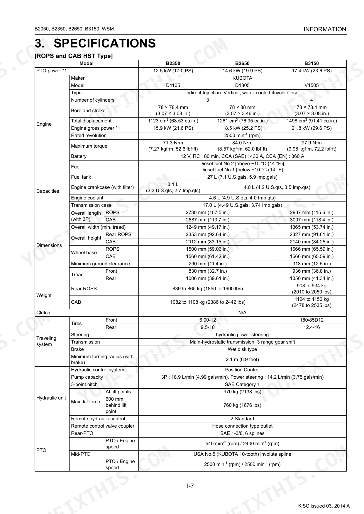
| I Information | 3-19 | Safety First, Safety Decals, Specifications, Traveling Speeds, Dimensions |
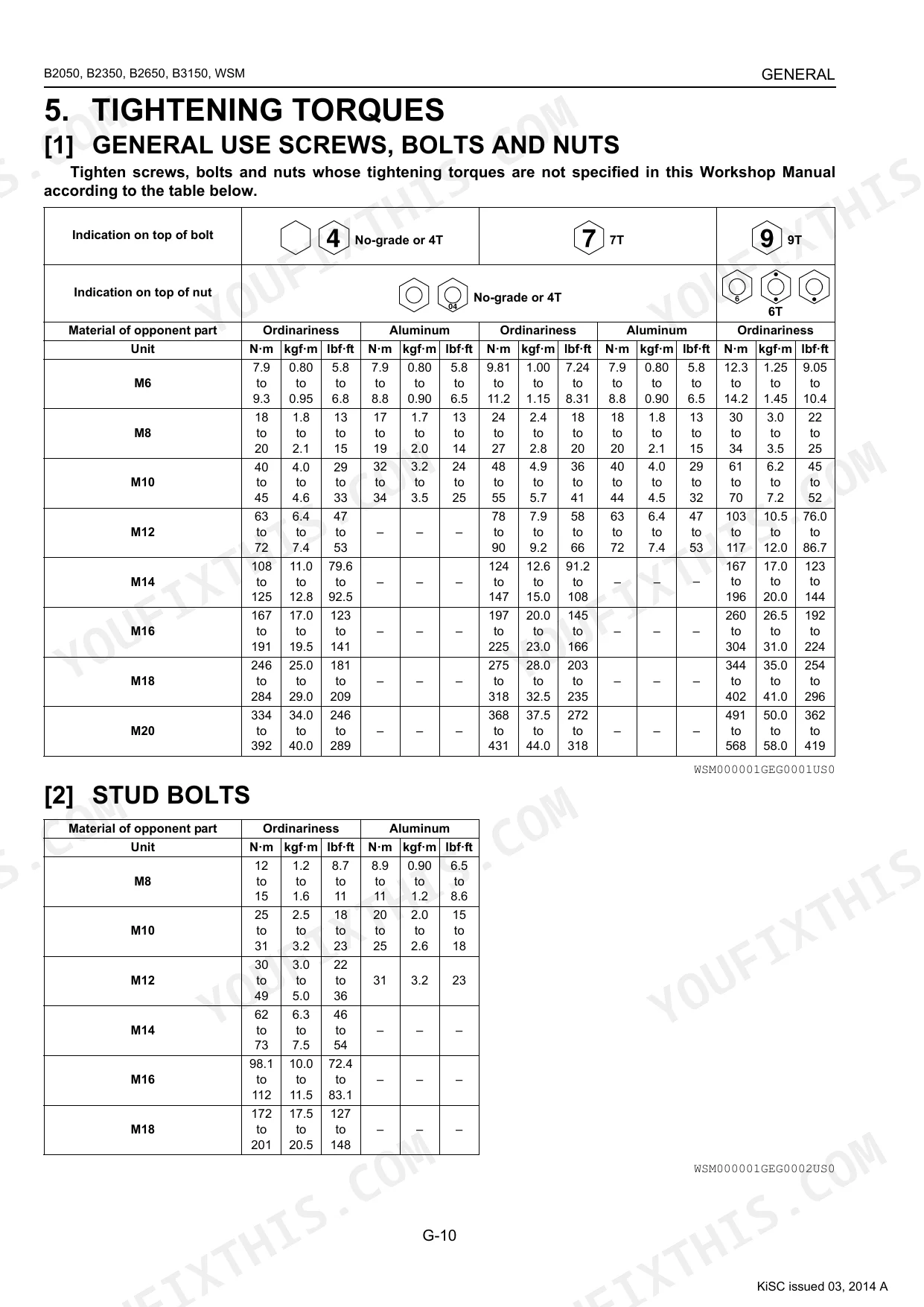
| G General | 20-83 | Tractor Identification, Handling Precautions For Electrical Parts And Wiring (Wiring, Battery, Fuse, Connector, Handling Of Circuit Tester, Color Of Wiring), Lubricants, Fuel And Coolant, Tightening Torques (Stud Bolts, Metric Screws, Bolts And Nuts, American Standard Screws, Bolts And Nuts With Unc Or Unf Threads, Plugs), Maintenance Check List, Check And Maintenance (Daily Check, Check Points Of Every 50 Hours, Check Points Of Every 100 Hours, Check Points Of Every 200 Hours, Check Points Of Every 400 Hours, Check Point Of Every 800 Hours, Check Point Of Every 1500 Hours, Check Point Of Every 3000 Hours, Check Points Of Every 1 Year, Check Points Of Every 2 Years, Others), Special Tools (Special Tools For Engine, Special Tools For Tractor, Special Tools For Cabin), Tires (Tire Pressure, Wheel Adjustment, Ballast), Implement Limitations |
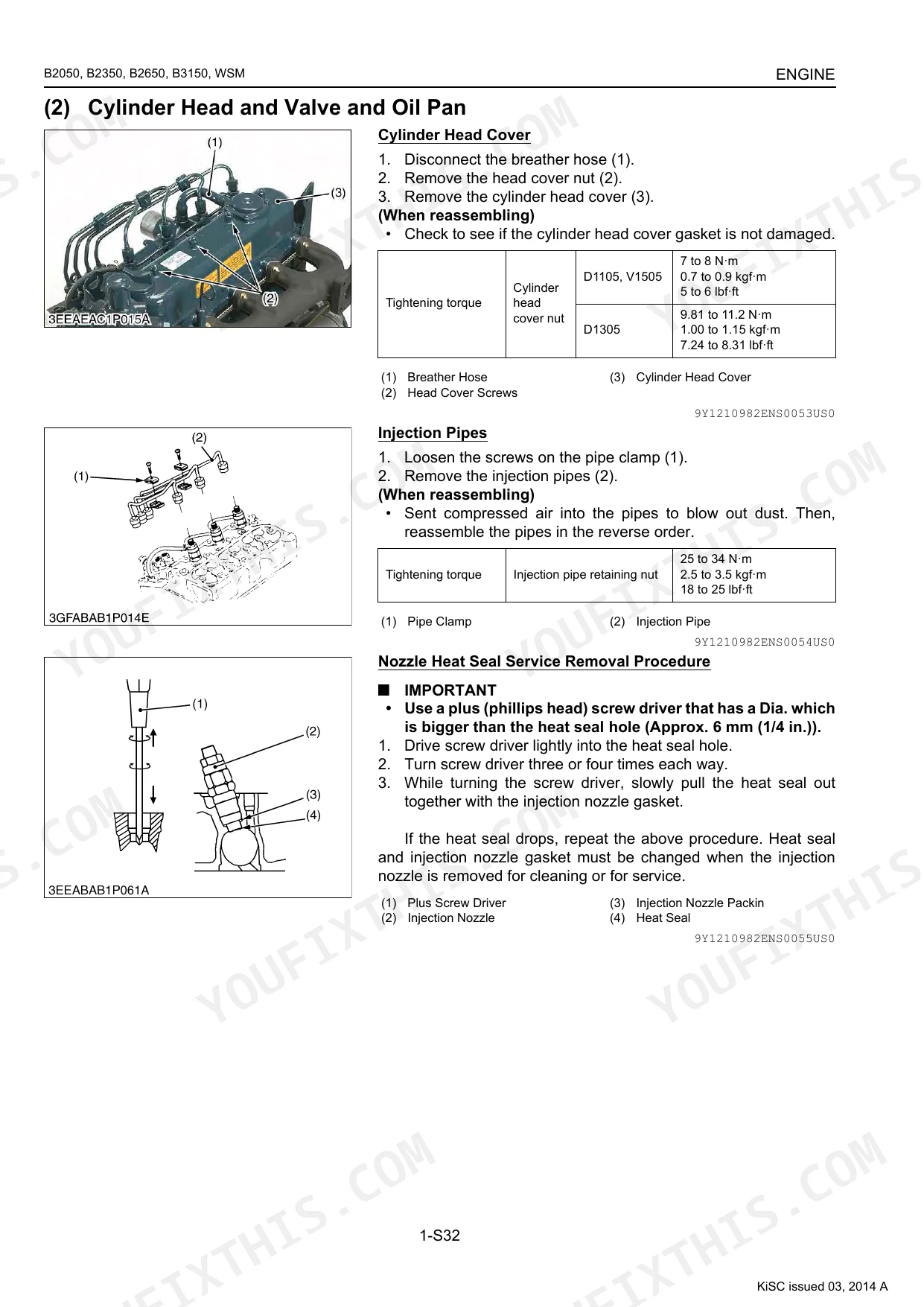
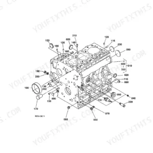
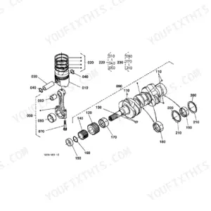
| 1 Engine | 84-150 | Engine Body (Closed Breather [d1105, V1505], Half-floating Head Cover [d1305], Governor), Troubleshooting, Servicing Specifications, Tightening Torques (Tractor Section, Engine Section), Checking, Disassembling And Servicing (Checking And Adjusting, Preparation, Disassembling And Assembling, Servicing) |
| 2 Clutch | 151-164 | Structure (Manual Transmission Model, Clutch Operation), Troubleshooting, Servicing Specifications, Tightening Torques, Checking, Disassembling And Servicing (Checking And Adjusting, Disassembling And Assembling, Servicing) |
| 3 Transmission | 165-277 | Structure (Manual Transmission, Hst), Front Case (Structure, Bi-speed Turn Linkage, Bi-speed Turn Powertrain), Manual Transmission (Structure), Hydrostatic Transmission (Structure, Pump And Motor, Oil Flow And Valves, Control Linkage), Cruise Control (Cruise Control Linkage [cabin Model], Cruise Control Linkage), Range Gear Shift Section, Front Wheel Drive Section, Pto System (Structure, Rear Pto Section, Rear Pto / Mid-pto Section, Mid-pto Section, Independent Pto), Differential Gear System (Differential Function, Differential Lock), Troubleshooting, Servicing Specifications, Tightening Torques, Checking, Disassembling And Servicing (Checking And Adjusting, Preparation, Disassembling And Assembling, Servicing) |
| 4 Rear Axle | 278-287 | Structure, Troubleshooting, Tightening Torques, Diassembling And Servicing (Diassembling And Assembling, Servicing) |
| 5 Brakes | 288-305 | Linkage (Rops, Cabin), Operation, Troubleshooting, Servicing Specifications, Tightening Torques, Checking, Disassembling And Servicing (Checking And Adjusting, Disassembling And Assembling, Servicing) |
| 6 Front Axle | 306-324 | Structure (Wheel Drive Model), Troubleshooting, Servicing Specifications, Tightening Torques, Checking, Disassembling And Servicing (Checking And Adjusting, Disassembling And Assembling, Servicing) |
| 7 Steering | 325-341 | Hydraulic Circuit, Steering Controller, Steering Cylinder, Hydraulic Pump, Troubleshooting, Servicing Specifications, Tightening Torques, Checking, Disassembling And Servicing (Checking, Disassembling, Servicing) |
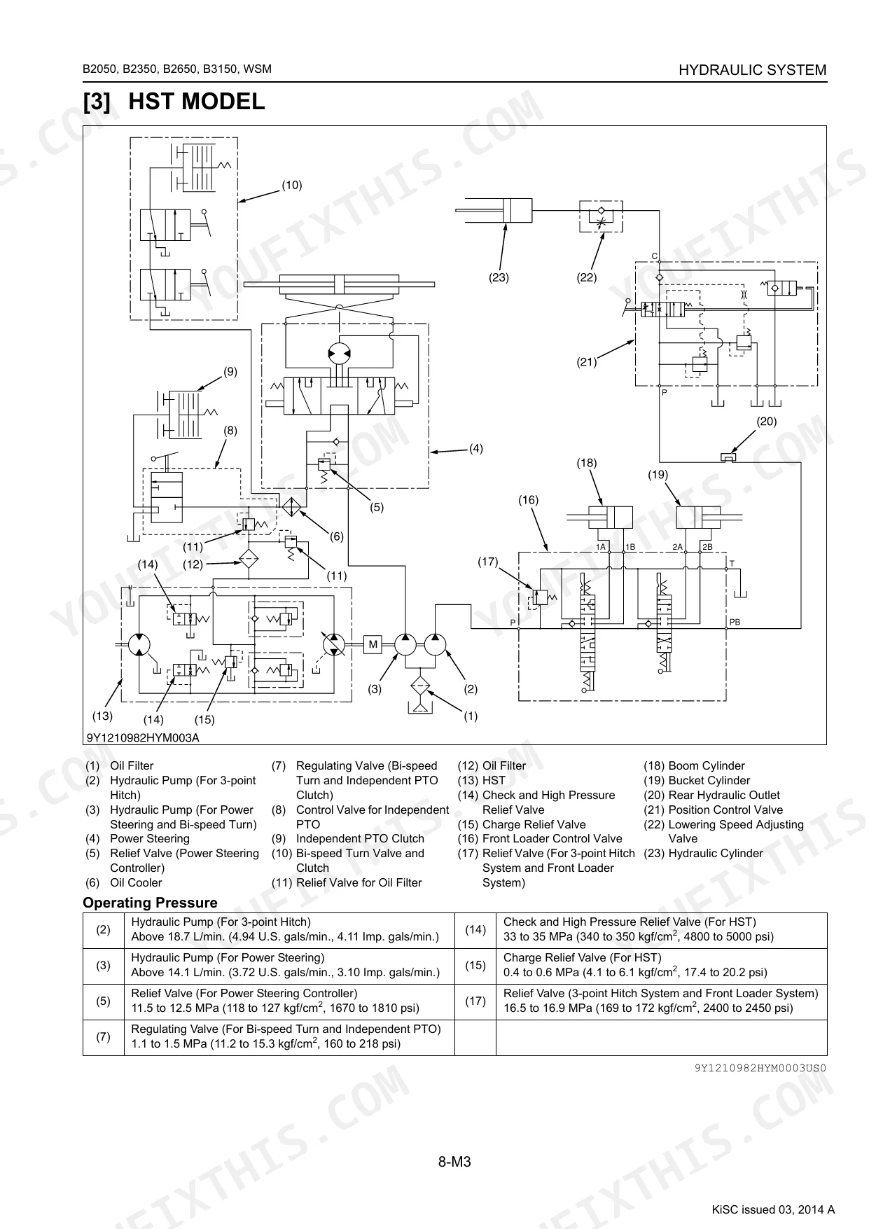
| 8 Hydraulic System | 342-390 | Hydraulic Circuit (Manual Transmission Model, Hst Model), Hydraulic Pump, Three Points Hydraulic System (Hydraulic Circuit, Relief Valve, Position Control Valve, Feedback Linkage For Position Control), Front Loader Control Valve (Structure, Operation), Remote Control Valve, Hydraulic Outlet (Manual Transmission Model, Troubleshooting, Servicing Specifications, Tightening Torques, Checking, Disassembling And Servicing (Checking And Adjusting, Disassembling And Assembling, Servicing) |
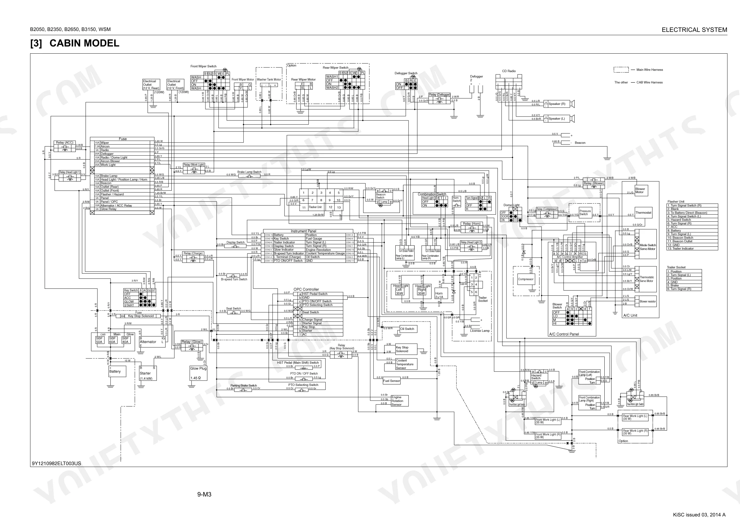
| 9 Electrical System | 391-473 | Wiring Diagram (Rops Model, B3150 Rops, Cabin Model), Engine Starting System And Stopping System (Opc System Circuit, Controller, Safety Switch, Starter, Key Stop Solenoid, Glow Plug), Charging System (Alternator, Ic Regulator), Lighting System (Head Light, Turn Signal Light, Hazard Light, Beacon, Brake Light, Work Light, Trailer Socket), Instrument Panel (Easy Checker™, Gauges And Other Indicators, Error Code Display, Switches And Sensors), Troubleshooting, Servicing Specifications, Tightening Torques, Checking And Adjusting (Battery, Fuse, Relays, Starting System, Charging System, Lighting System, Warning Lamp, Indicator Lamp And Gauge), Disassembling And Assembling (Starter, Alternator), Servicing (Starter |
| 10 Cabin | 474-539 | Outline Of Air Conditioning System (Structure, Air Conditioning System), Refrigeration System (Compressor, Condenser, Receiver, Air Conditioner Unit), System Control, Electrical System (Electrical Circuit, Relay), Troubleshooting, Servicing Specifications, Tightening Torques, Precautions At Repairing Refrigerant Cycle (Handling Of Service Tools), Checking And Charging Refrigerant Cycle (Checking With Manifold Gauge, Discharging, Evacuating And Charging), Checking, Disassembling And Servicing (Checking And Adjusting, Disassembling And Assembling, Servicing) |
Quick Reference Specifications
| Specification | Value | Page |
|---|---|---|
| All Models | ||
| Front axle holder mounting bolt | 200 to 230 N·m | p. 315 |
| Front wheel mounting nut | 77 to 90 N·m | p. 42 |
| Seat Switch Continuity (Operator on the seat) | 0 Ω | p. 445 |
| PTO Clutch Lever Switch Continuity (disengaged) | 0 Ω | p. 445 |
| Hydraulic Oil Filter Tightening | Tighten by hand an additional 1/2 turn only | p. 56 |
| Transmission fluid type | KUBOTA UDT or SUPER UDT fluid | p. 29 |
| Transmission case capacity (HST Type) | 17 L | p. 29 |
| Hydraulic Pump (For 3-Point Hitch) Delivery (At Rated Pressure) | Above 18.3 L/min. | p. 370 |
| B2650 | ||
| Rear wheel mounting nut and screw | 108 to 126 N·m | p. 42 |
| Manual transmission model | ||
| Shuttle shift lever switch Continuity (neutral) | 0 Ω | p. 445 |
| HST model | ||
| HST Pedal Switch Continuity (neutral) | 0 Ω | p. 445 |
| Manual Transmission Model | ||
| 3-Points Hitch Relief Valve Setting Pressure | 15.5 to 16.5 MPa | p. 377 |
Kubota B2050–B3150 Series Common Problems This Manual Covers
Kubota B2650 three-point hitch won't lift implements or raises slowly and intermittently
Start with the transmission fluid level; top up with KUBOTA UDT or SUPER UDT fluid (page 29). Pull and inspect the hydraulic suction screen for debris. Replace the hydraulic filter hand-tight plus 1/2 turn only (page 56). If the hitch still won't lift, test pump delivery: minimum acceptable output is above 15.3 L/min at rated pressure (page 370). Inspect the position control valve and feedback linkage if pump output passes.
Manual Section: Hydraulic System TroubleshootingEngine cranks or starts with PTO engaged after operator leaves the seat p. 445
Test the seat switch with a multimeter: it must read 0 Ω continuity when seated (page 445). Cross-check the OPC wiring diagram. Also verify the PTO clutch lever switch reads 0 Ω when disengaged and the neutral switch closes in the neutral position. Replace any switch that fails continuity. Inspect the harness for corroded connectors or chafed wires between the switches and the OPC controller.
Manual Section: Electrical System TroubleshootingMid or rear PTO shaft keeps spinning after operator stands up from seat p. 445
Verify the seat safety switch: operator seated = 0 Ω, seat empty = open circuit (page 445). If it fails to open when unoccupied, replace it. Check the PTO clutch lever switch at the same 0 Ω spec. Trace the OPC circuit from each switch to the controller using the wiring diagram; look for shorts or corroded connector pins keeping the interlock circuit closed.
Manual Section: Electrical System TroubleshootingEngine won't start or cranks slowly in cold weather with no glow response
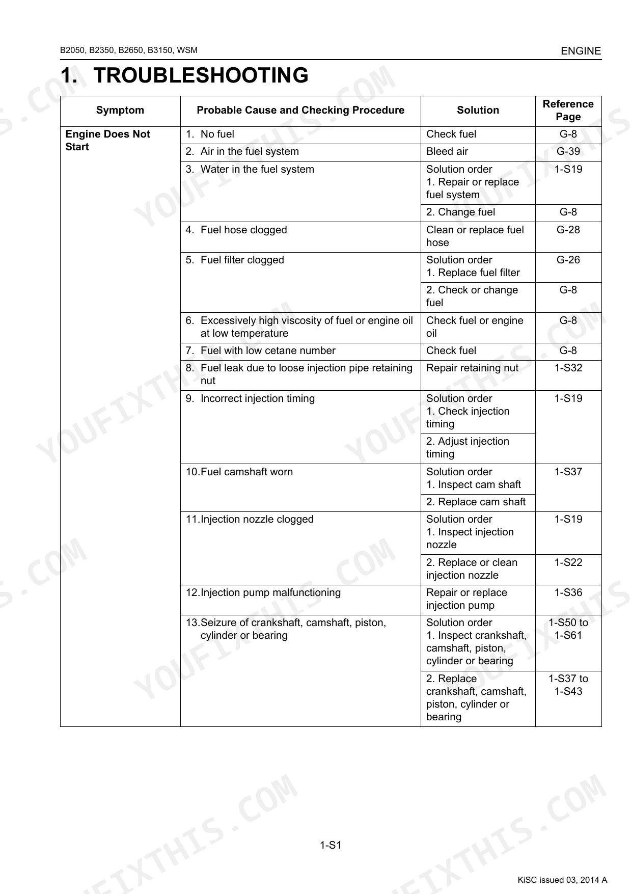
Open the engine troubleshooting chart first. Confirm battery voltage is above 12.4V and clean the terminals. Verify the glow plug circuit activates on key-on before cranking. The fuel tank holds 27 L (page 11); bleed the fuel system if the tractor sat unused. Check that the seat switch and neutral switch both read 0 Ω in their safe positions (page 445) to rule out an interlock fault blocking the start circuit.
Manual Section: Engine TroubleshootingHydrostatic transmission loses drive power or won't move in forward or reverse
Confirm the transmission fluid level; HST models hold 17 L of KUBOTA UDT or SUPER UDT fluid (page 29). Verify the HST pedal returns fully to neutral: the pedal neutral switch must read 0 Ω in the neutral position (page 445). Inspect the control linkage and return spring for binding or wear. If fluid and linkage both pass, examine the HST pump and motor per Section 3 Transmission for internal wear.
Manual Section: Hydrostatic Transmission (HST) TroubleshootingSafety interlock start system passes bench test but behaves differently on the tractor p. 445
Pull the wiring diagrams and compare the OPC circuit layout against the operator manual description; the two are known to conflict on the B-series. Verify each safety switch reads 0 Ω in its safe position (page 445): seat switch seated, PTO lever disengaged, neutral switch in neutral. Inspect relay operation in the starting system and look for factory wiring deviations from the schematic before assuming a component fault.
Manual Section: Electrical System TroubleshootingFrequently Asked Questions
How do I clear error codes on a Kubota B2350 or B2650?
For CABIN models, if a trouble code appears, first try restarting the machine. If the trouble is not corrected by restarting, you must solve the problem according to the troubleshooting table on page 9-M33. For example, error code 'Err 3' (Meter panel memory reading trouble) requires replacing the meter panel. There is no manual procedure to simply clear the codes without addressing the fault.
What does the warning light or code mean on a Kubota B3150?
On CABIN models, the instrument panel can display error codes. 'Err 1' indicates a water temperature sensor power circuit trouble. 'Err 2' signifies a fuel sensor power circuit trouble. 'Err 3' means there is a meter panel memory reading trouble. For each code, the manual suggests checking battery voltage or replacing the meter panel as a solution.
What are the torque specs for Kubota B2050/B2350/B2650/B3150 wheel bolts?
The front wheel mounting nuts for all models should be torqued to 77-90 N·m (58-66 lbf·ft). For the B2050, B2350, and B2650, the rear wheel mounting nut and screw torque is 108-126 N·m (79.7-92.9 lbf·ft). For the B3150, the rear wheel mounting nut is 167-191 N·m (123-141 lbf·ft), and the rear wheel mounting screw is 196-225 N·m (145-166 lbf·ft).
What are the torque specs for Kubota B2650 loader or front axle bolts?
For the LA424 loader on a B2650, the M14 main frame attachment bolts require 130 N·m (95.9 lbf·ft) of torque. The front axle holder mounting bolts have a torque specification of 200 to 230 N·m (147.5 to 169.6 lbf·ft). Always check the specific bolt size and location before tightening.
What do I get after purchasing this Kubota B2050, B3150 manual?
Right after checkout you can download the 539-page searchable PDF. It opens on a laptop, tablet, or phone, so you can bring it straight to the shop floor.
Are there any print restrictions on this Kubota B2050, B3150 manual?
Yes. The PDF carries no DRM, so you can print any page or section you need for the shop. It works with any standard printer.
Are electrical wiring diagrams included in this Kubota B2050, B3150 manual?
Yes, this Kubota B2050, B3150 Workshop Manual includes complete electrical wiring diagrams, wire routing, and connector pinouts.
Document Quality
This is a native digital PDF, not a scanned document, so the full text is searchable and can be copied. The text is sharp and easy to read, and many diagrams are high-quality vector line art that remains clear at any zoom level. Photographs and some illustrations are raster images, which are clear but may become pixelated when magnified significantly; all labels are legible. The pages are clean and well-formatted, with a few intentionally blank pages serving as section dividers.


Reviews
There are no reviews yet.