
This Kubota l35 service manual pdf (OEM #11640) runs 503 pages on a single tractor, the Kubota L35, from engine internals through the Glide Shift Transmission, wet disc brakes, loader, and backhoe. Hydraulic schematics trace every circuit from the GST valve assembly out to the loader and backhoe control valves; wiring diagrams map the starting system, glow control, and charging circuit. Torque tables, clearance data, and troubleshooting across the major systems are all included. You'll find cold valve clearance at 0.18 to 0.22 mm, cylinder head screws torqued to 93.1 to 98.0 N·m (68.7 to 72.3 ft-lbs), and backhoe relief pressure set between 17.2 and 17.7 MPa. Stop chasing specs on forums. The bookmarked, keyword-searchable PDF opens on any device and jumps straight to the number you need.
What's Inside This Kubota L35 Manual
| System | Pages | Key Topics |
|---|---|---|
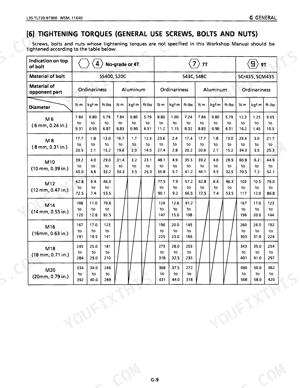
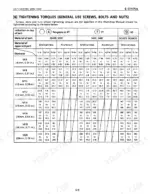
| General | 8-49 | Features, Tractor Identification, Handling Precautions for Electrical Parts and Wiring, Lubricants, Fuel and Cooling Water, Tightening Torques |
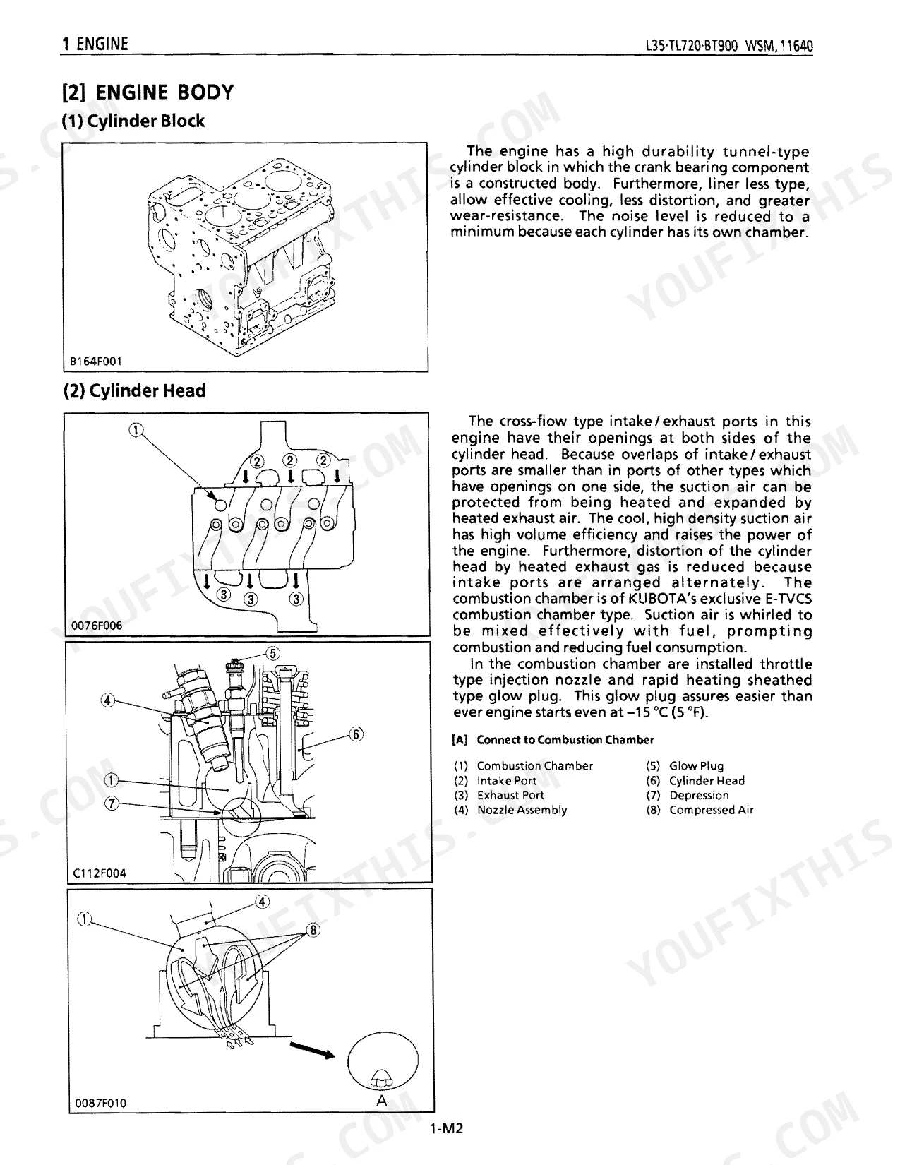
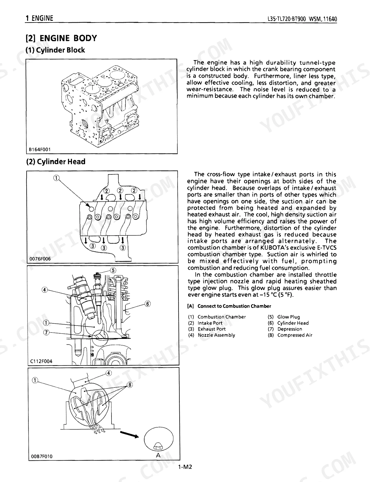
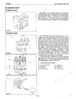
| Sect 1 Engine | 50-119 | Features, Engine Body (Cylinder Block, Cylinder Head, Crankshaft, Piston and Piston Rings, Connecting Rod, Camshaft, Rocker Arm, Intake and Exhaust Valves, Flywheel) |
| Sect 2 Clutch | 120-135 | Features, Linkage Mechanism, Operation |
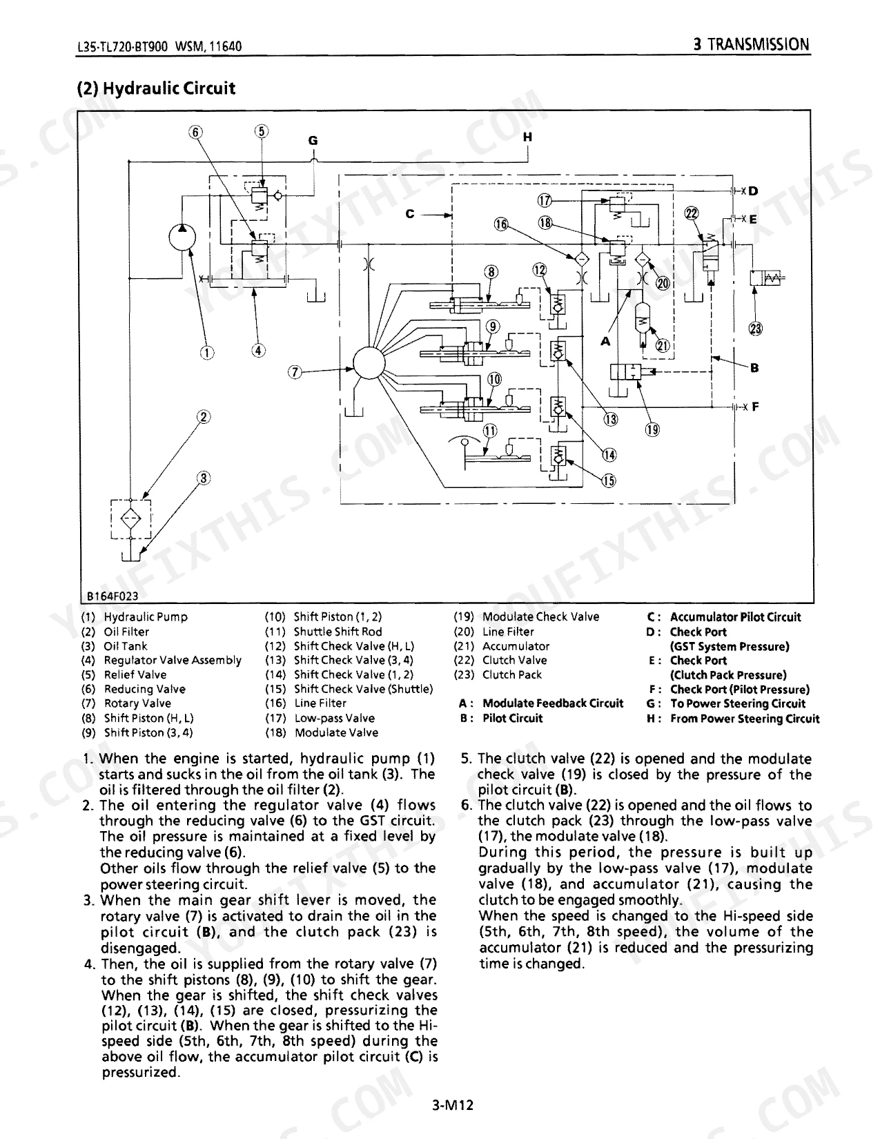
| Sect 3 Transmission | 136-227 | Structure, Power Train (Main Gear Shift Section, Shuttle Shift Section, Hi-Lo Range Shift Section, Rear PTO Shift Section, One-Way Clutch, Front Wheel Drive Section) |
| Sect 4 Rear Axle | 228-237 | Features, Tightening Torques, Checking, Disassembling and Servicing (Draining the Transmission Fluid, Rear Wheel and Fenders, Rear Axle Case, Disassembling Rear Axle) |
| Sect 5 Brakes | 238-251 | Features (Wet Disc Brakes, Fade, Relationship between temperature and friction coefficient of brake disc), Operation (During Braking), Troubleshooting, Servicing Specifications |
| Sect 6 Front Axle | 252-271 | Structure, Front Wheel Alignment (Camber, Kingpin Angle, Caster, Toe-in), Troubleshooting, Servicing Specifications, Tightening Torques, Checking |
| Sect 7 Steering | 272-303 | Features, Hydraulic Circuit, Steering Controller (Control Valve, Metering Device, Relief Valve), Oil Flow, Steering Cylinder |
| Sect 8 Hydraulic | 304-337 | Hydraulic Circuit, Structure, Hydraulic Pump, Oil Filter, Position Control Valve, Position Control Linkage, Hydraulic Cylinder, Relief Valve |
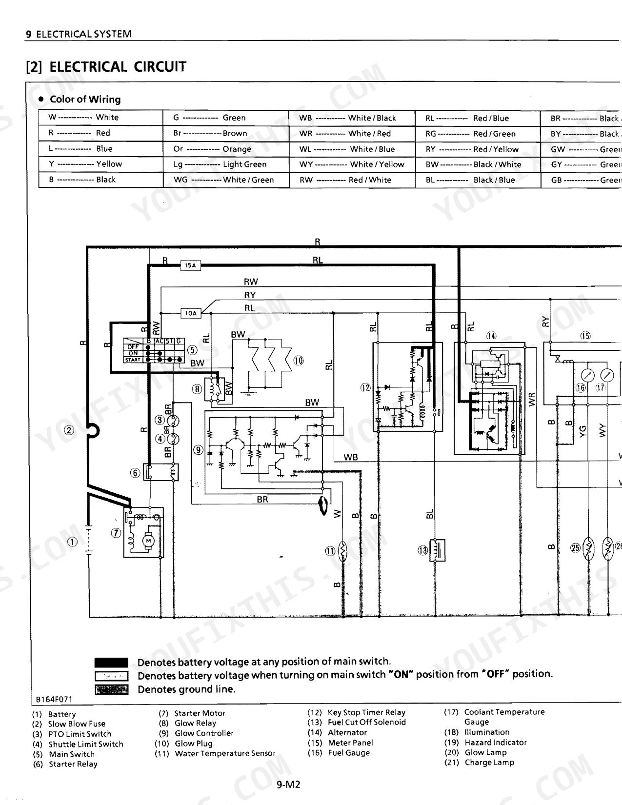
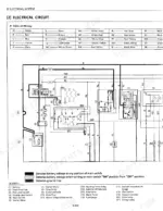
| Sect 9 Electrical | 338-397 | Wiring Diagram, Electrical Circuit, Starting System (Starter Motor, Roller Clutch, Magnet Switch, Operation of Starter Motor, Glow Control System) |
| ROPS FOPS | 398-403 | - |
| Loader | 404-445 | Features, Hydraulic System (Hydraulic Circuit, Control Valve Assembly), Feedback Linkage, Boom Cylinder and Bucket Cylinder |
| Backhoe | 446-503 | Features, Hydraulic System (Hydraulic Circuit, Control Valve, Overload Relief Valve, Lockout Valve), Hydraulic Cylinder, Quick Coupler |
Quick Reference Specifications
| Specification | Value | Page |
|---|---|---|
| Hydraulic fluid level check | between the two notches | p. 427 |
| Cylinder head screws tightening torque | 93.1 to 98.0 N·m, 9.5 to 10.0 kgf·m, 68.7 to 72.3 ft-lbs | p. 77 |
| Valve Clearance (When Cold) | 0.18 to 0.22 mm, 0.0071 to 0.0087 in. | p. 72 |
| Relief Valve of Hydraulic Cylinder Body Setting Pressure | 17.2 to 17.7 MPa, 175 to 180 kgf/cm2, 2489 to 2560 psi | p. 482 |
| Maximum PTO power | 19.4 kW (26 HP) | p. 5 |
| Total displacement | 1647 cm³ (100.5 cu.in.) | p. 5 |
| Fuel tank capacity | 35 L (9.2 U.S. gals., 7.7 Imp. gals.) | p. 5 |
| Engine crankcase oil capacity | 4.8 L (5.1 U.S. qts., 4.2 Imp. qts.) | p. 5 |
| Transmission case capacity | 39 L (41.2 U.S. qts., 34.3 Imp. qts.) | p. 5 |
| Front tire pressure | 274 kPa (2.8 kgf/cm², 40 psi) | p. 44 |
| Rear tire pressure | 207 kPa (2.1 kgf/cm², 30 psi) | p. 44 |
| Front wheel mounting lug nuts torque | 137 N·m (14 kgf·m, 100 ft-lbs) | p. 25 |
Kubota L35 Common Problems This Manual Covers
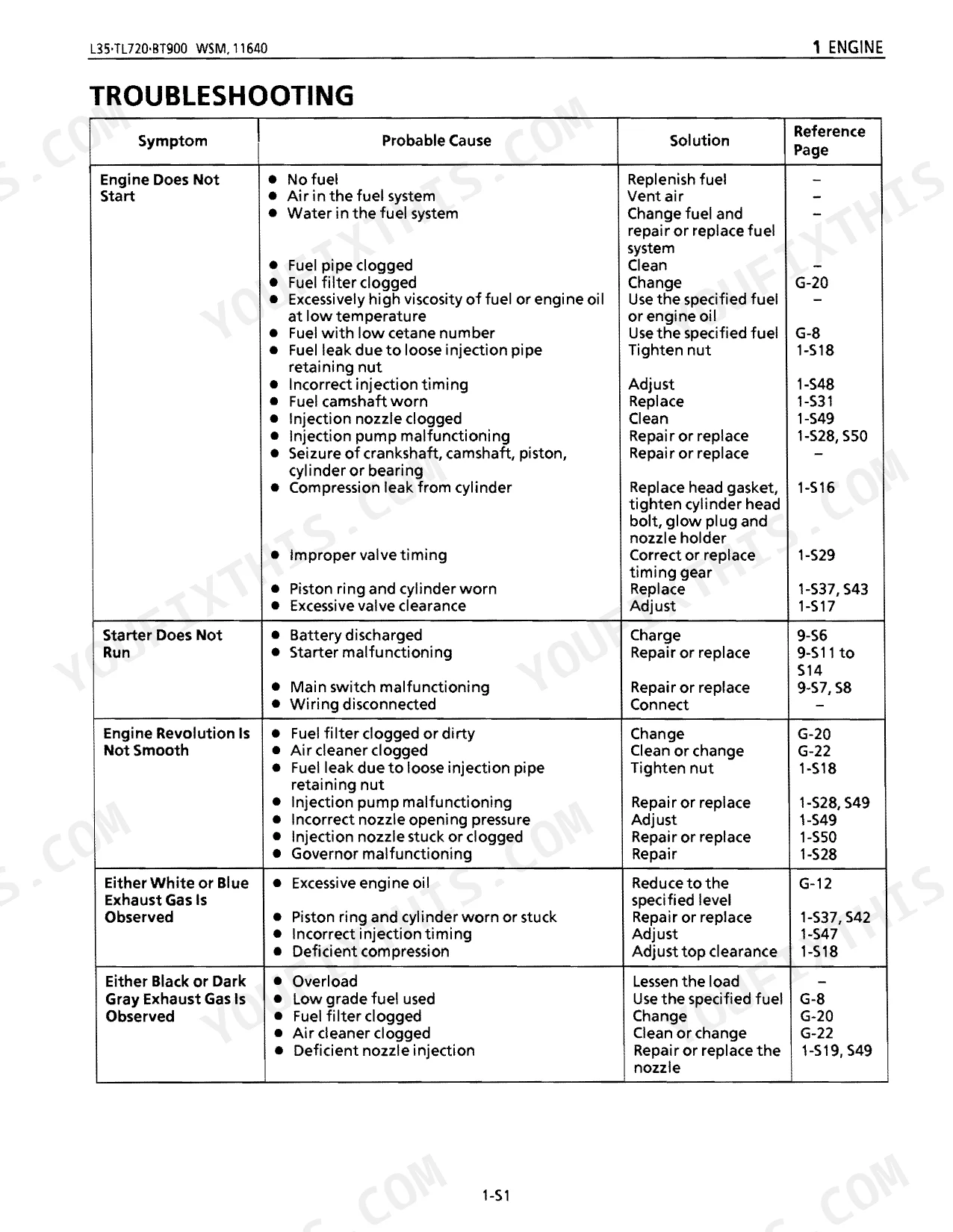
Kubota L35 engine or driveline cannot be turned over by hand and tractor appears mechanically locked
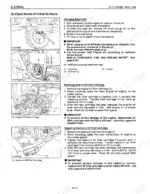
Inspect the engine body by turning the crankshaft by hand to isolate the lockup. If you tear down the top end, torque the cylinder head screws to 93.1 to 98.0 N·m (68.7 to 72.3 ft-lbs) as shown on page 77, and confirm valve clearances of 0.18 to 0.22 mm.
Manual Section: Engine TroubleshootingLoader boom does not rise or lift capacity drops significantly during heavy excavation
Test the setting pressure on the hydraulic cylinder body relief valve. Adjust it to 17.2 to 17.7 MPa (2489 to 2560 psi) per the specs on page 482. Confirm the hydraulic fluid sits between the two notches on the dipstick, per page 427.
Manual Section: Front Loader TroubleshootingStarter motor does not operate and battery discharges too quickly when turning the key
Check the wiring diagram to trace the starting system circuit, then inspect the magnet switch and roller clutch. Verify battery voltage and clean the ground connections. Fill the engine crankcase with 4.8 L (5.1 U.S. qts.) of oil so viscosity holds up on cold starts.
Manual Section: Electrical System TroubleshootingWet clutch slips under load or chattering occurs during normal transmission operation
Measure the clutch pedal free travel and adjust the linkage mechanism until it falls between 20 to 30 mm, as specified on page 27. If the internal wet discs are slipping, drain the transmission fluid and refill with 39 L (41.2 U.S. qts.).
Manual Section: Clutch TroubleshootingFrequently Asked Questions
Why won’t the Kubota L35 start after the glow plug light goes out?
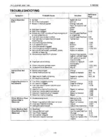
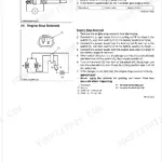
If the starter motor does not operate after the glow plug light goes out, consult the "STARTING SYSTEM" troubleshooting table. Probable causes include a discharged or defective battery (recharge or replace, page 9-S5, S6), an improperly adjusted PTO limit switch (repair or replace, page 9-S9), or disconnected/improperly connected wiring harness (repair or replace, page 9-M1, M2). Other potential issues are a blown slow blow fuse or a defective starter motor or main switch.
How do I troubleshoot hydraulic problems on a Kubota L35?
For hydraulic faults, work from the "8 HYDRAULIC SYSTEM TROUBLESHOOTING" table on page 322. When the implement does not rise (no noise), check the control linkage for adjustment (page 8-S7) or a damaged hydraulic piston O-ring (replace, page 8-S11). When oil temperature climbs fast, look at relief valve operation (adjust, page 8-S8) or hydraulic pump leaks (replace or repair, page 8-S6).
How to check Kubota L35 hydraulic fluid level
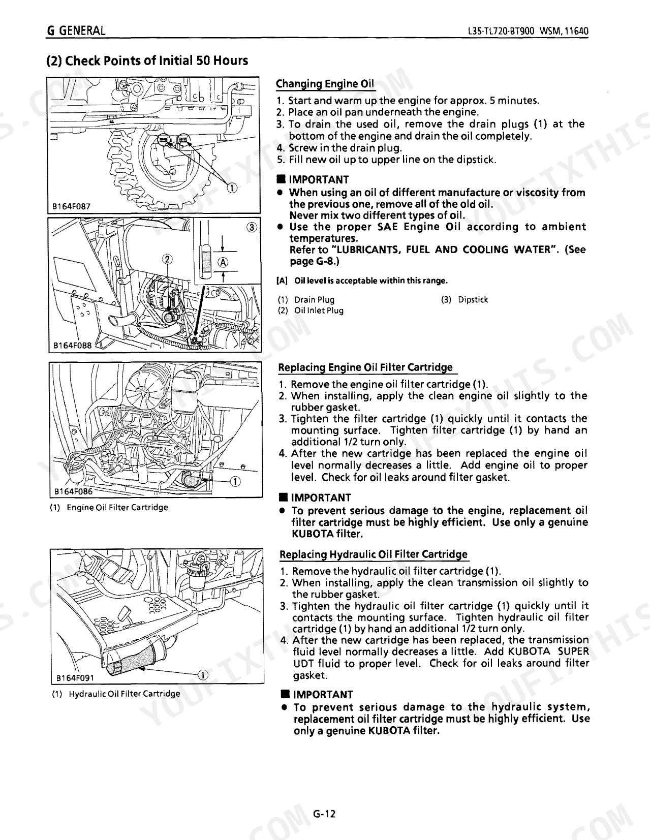
Pull the dipstick (1), wipe it clean, reinsert it, then pull it again and read the level against the two notches. Top up with KUBOTA SUPER UDT fluid if it sits low. Transmission fluid capacity is 39.0 L (41.2 U.S. qts., 34.3 Imp. qts.).
Is this Kubota L35 Service Manual a digital download?
A 503-page Service Manual in searchable PDF, ready the moment you finish checkout. Read it on a computer, tablet, or phone, with no shipping wait.
Are there any print restrictions on this Kubota L35 manual?
Absolutely. No DRM or copy protection. Print the whole manual or just the pages you need. Any home or office printer works.
Does this Kubota L35 manual include hydraulic schematics?
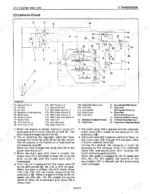
Yes. Complete hydraulic schematics are included, with flow diagrams, valve configurations, and pressure specifications.
Document Quality
This document is a scanned PDF with an OCR layer, so you can search and copy the full text. The text is generally clear and readable, though it exhibits the slight fuzziness characteristic of scanned documents rather than crisp digital text. Diagrams and illustrations are raster images; they are mostly clear, and their labels are readable, though some smaller text on decals may appear slightly blurry. Pages are clean with no significant scan artifacts, stains, or skewed content. No notable blank or filler pages are present.



Reviews
There are no reviews yet.