


Part of the Yanmar Parts Manuals.
All 126 pages of this Yanmar B27-2A Parts Catalog (OEM #000Y00S3480) focus on one machine: the B27-2A Crawler Backhoe Excavator, covering all four variants including B27-2A-CR-AY-1, B27-2A-C-AY-1, B27-2A-PR-AY-1, and B27-2A-P-AY-1. You get exploded-view diagrams with OEM part numbers for every assembly, from fuel tank and accelerator linkage to the hydraulic oil pump, remote control joystick, and all five cylinder assemblies. A wiring diagram is included for the electrical harness, and the hydraulic system (oil pump, cylinders, valves, and lines) is broken out in exploded views so you can trace the fluid circuit part by part. Factory component dimensions are locked in throughout: the arm/bucket link shim set measures 42 x 25.5 x 0.5mm, the work lamp calls for a 24V-6W bulb, and the electrical circuit runs a 15A fuse. Stop ordering the wrong part because you couldn't pin down the number. Bookmarked by section; search any assembly by keyword and land on the right exploded view in seconds.
What's Inside This Yanmar B27-2A Parts Manual
| System | Pages | Key Topics |
|---|---|---|
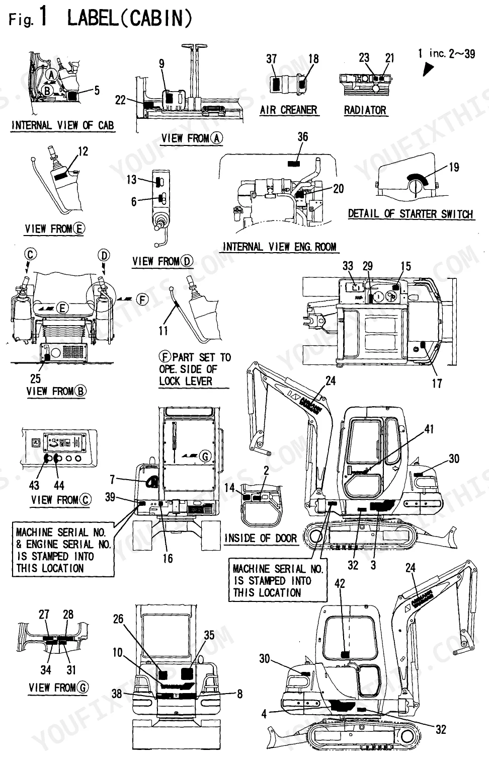
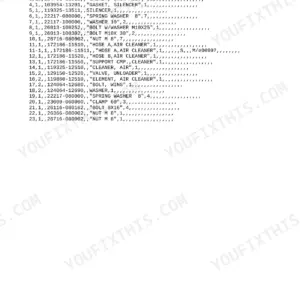
| Label | 7-8 | Accelerator, P.T.O., Air Cleaner, Fuel, Starter Switch, Radiator |
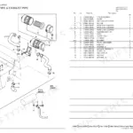
| Muffler | 9-10 | Pipe, EXH.EXTENTION, Clamp, Washer, Spring Washer, Bolt, Nut |
| Air Cleaner | 11-12 | Hose, Clamp 350, Clamp 70 |
| Accelerator | 13-14 | Lever, Accel, Grip, Cable, ACCEL(S), Joint, Clamp |
| Engine Mount | 15-16 | Absorber, Shock, MOUNT(R), Engine, Bracket, MOUNT(L), Plate |
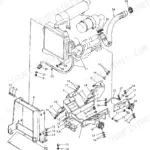
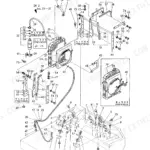
| Radiator & Heater Parts | 17-18 | Mount, Radiator, Pipe, C.W., Radiator Sub-Assy, Sub-Tank Assy, Joint, COOL.WTR.PIPE |
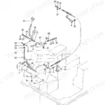
| Fuel Tank & Fuel Line | 19-24 | Tank Assy, Fuel, Gauge Unit, Cap, Fuel Tank, Strainer, Fuel Inlet |
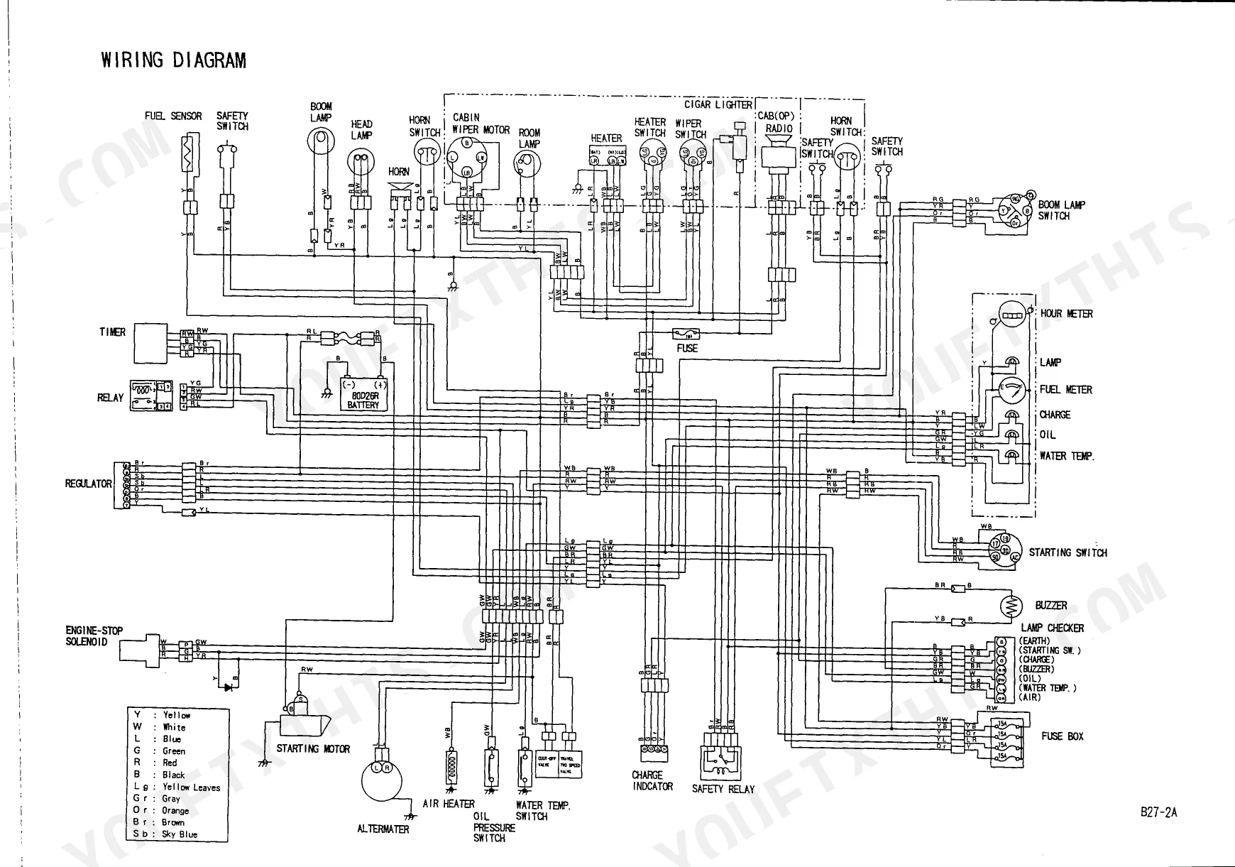
| Electric Part | 25-28 | Wiring |
| Work Lamp | 29-30 | Wire, Lamp, Work, Bulb 15V-60W, Band, Cover |
| Heater | 31-34 | Joint, Valve, Miniature, Switch, Connector PT3/8-M16 |
| Control Equipment | 35-52 | Lever Stand, Drive, Swing, Blade, Cut Off Lever & L, P.T.O. Control |
| Seat Mount | 53-54 | Lever Lock, Hook Comp. Key, Bonnet, Plate Catch, Washer |
| Bonnet | 55-56 | Roof Comp. Canopy, Column R, Column L, Canopy F Comp., Spring Washer, Bolt |
| Canopy | 57-60 | Roof Comp. Canopy, Column R, Column L, F Comp., Spring Washer, Bolt |
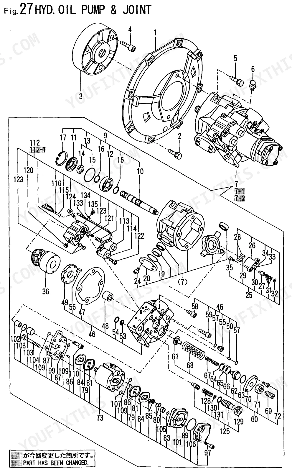
| Hyd. Oil Pump & Joint | 61-62 | Cover Flywheel, Coupling, Shaft Assy. Rocker, Piston Assy. Control |
| Boom Cylinder | 63-64 | - |
| Arm Cylinder | 65-66 | - |
| Bucket Cylinder | 67-68 | Cylinder Assy, Tube Assy, Rod Assy, Head, Piston, Seal Kit |
| Swing Cylinder | 69-70 | Cylinder Assy, Tube Assy, Rod Assy, Head, Piston, Seal Kit |
| Blade Cylinder | 71-88 | Cylinder Assy, Tube Assy, Rod Assy, Head, Piston, Seal Kit |
| Remote Control | 89-94 | Joy-Stick, Valve Assy, Section Set, Spool, Cable, Handle |
| Hyd. Oil Tank | 95-99 | Joint, Clamp, O-Ring, Connector, Flange, Hose |
| Hyd. Oil Piping | 100-113 | Tank-Pump-Valve, Valve-Motor, Boom, Valve-Swivel, Swing, Return, P.T.O Valve, Frame |
| Control Piping | 114-117 | Remote Control Valve, Hyd. Oil Pump, Swivel Joint, Control Valve |
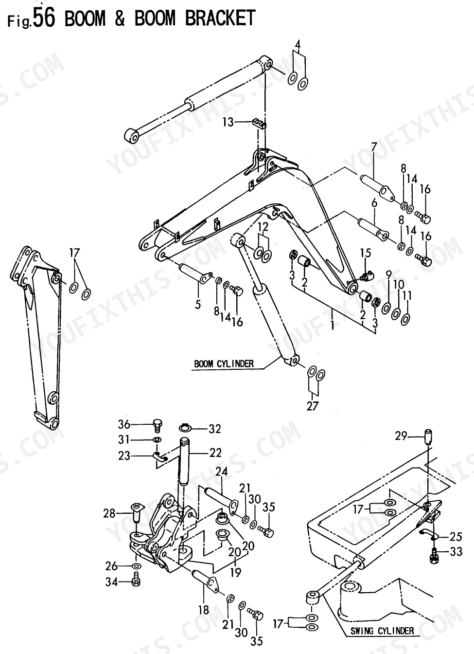
| Boom & Boom Bracket | 118-121 | Boom Assy, Bush, Seal, Pin, Spacer, Bracket |
| Arm & Bucket Link | 122 | Spacer, Shim Set, Pin 38, Blade, Seal, Dust, Pin |
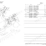
| Blade | 123-126 | - |
Quick Reference Specifications
| Specification | Value | Page |
|---|---|---|
| Fuse Rating | 15A | p. 26 |
| Bulb Voltage/Wattage | 24V- 6W | p. 26 |
| Spacer Dimensions | 75mm x 2.6mm | p. 31 |
| Wire Dimensions | 1.6mm x 170mm | p. 31 |
| Shim Dimensions | 42mm x 25.5mm x 0.5mm | p. 35 |
| O-Ring Dimensions | 27mm x 5.7mm | p. 37 |
| Spring Pin Dimensions | 5mm x 32mm | p. 35 |
| Grommet Dimensions | 16mm x 20mm x 4.5mm | p. 24 |
| Seal Dimensions | 45mm x 55mm x 4mm | p. 62 |
Yanmar B27-2A Common Problems This Manual Covers
Need the exact replacement part number for an Yanmar B27-2A leaking main hydraulic pump input shaft
Inspect the exploded diagram on page 62 to locate the pump shaft components. Find the exact part number for the dust seal measuring 45mm x 55mm x 4mm. Cross-reference this number with the parts index to order the correct replacement kit for your specific serial number.
Manual Section: Hyd. Oil Pump & Joint p. 62Cannot identify the correct replacement components for a blown main electrical harness fuse
Check the electrical system breakdown on page 26 to identify the correct fuse holder components. Verify the exact part number for the 15A fuse required for this circuit. Match this part number with the wiring diagram list before ordering a replacement to restore power.
Manual Section: Electric Part p. 26Need the exploded view to locate the leaking fuel tank inlet connection gasket
Review the fuel tank assembly breakdown on page 24. Locate the exact part number for the rubber grommet measuring 16mm x 20mm x 4.5mm. Use this specific part number when ordering from your dealer to ensure a proper fit at the fuel line connection.
Manual Section: Fuel Tank & Fuel Line p. 24Struggling to find the correct part number for a leaking pilot control valve fitting
Examine the control equipment parts diagram on page 37 to view the entire valve assembly. Identify the specific part number for the sealing O-ring measuring 27mm x 5.7mm. Order this exact factory part number to ensure proper sealing pressure at the control lever stand connections.
Manual Section: Control Equipment p. 37Frequently Asked Questions
What are the replacement specifications for hydraulic filters?
The hydraulic oil tank assembly includes a suction strainer, part number 172112-74801, and two elements, part numbers 172112-74911 and 172165-75481, which function as hydraulic filters. These are components of the hydraulic oil tank. p. 95
How will I receive this Yanmar B27-2A Parts Catalog?
This is a 126-page searchable PDF (3 MB) ready for immediate download. Works on any device, so pull it up on your phone while you're under the hood. No shipping, no waiting.
Can I print specific sections of this Yanmar B27-2A Parts Catalog?
Absolutely. No DRM or copy protection. Print the whole manual or just the pages you need. Any home or office printer works.
Are there wiring harness diagrams in this Yanmar B27-2A manual?
Yes, this Yanmar B27-2A Parts Catalog includes a wiring diagram for the electrical system.
Reviews
There are no reviews yet.