


Part of the Yanmar Parts Manuals.
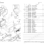
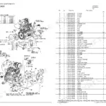
All 110 pages of this Yanmar B05 Parts Catalog (OEM #Y00K2642) cover every replaceable component across the B05 G, B05 P, B05 Y, B05 G EX, and B05 G AY crawler backhoes built from 1990 to 1996. Open it and you get exploded-view figures for the complete machine: control valves, hydraulic oil piping, all five cylinder assemblies, driving and turning motors, swivel joint, and the full crawler undercarriage. Wiring diagrams and hydraulic schematics are included so you can trace a circuit or a fluid line, then pull the correct OEM part number right from the diagram. The electrical section puts the 10A fuse spec next to its part number so your replacement order is right the first time. No more reading a worn label and hoping the number is still legible. Download now, open on any device, and use the built-in bookmarks to jump straight to the assembly you need.
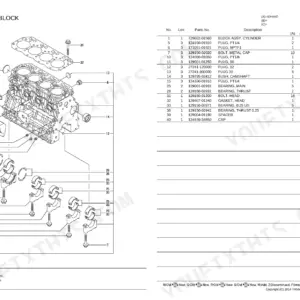
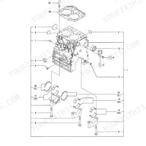
What's Inside This Yanmar B05 G / P / Y (Crawler Backhoe) Parts Manual
| System | Pages |
|---|---|
| Label | 0-0 |
| Safety Label | 0-0 |
| Control Equipment | 0-0 |
| Link Stand, Cover & Instrument Panel | 0-0 |
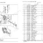
| Control Valve | 0-0 |
| Hyd. Oil Piping | 0-0 |
| Boom & Arm | 0-0 |
| Arm Cylinder | 0-0 |
| Work Lamp | 0-0 |
| Accelerator | 0-0 |
| Battery | 0-0 |
| Electric Part | 0-0 |
| Seat & Bonnet | 0-0 |
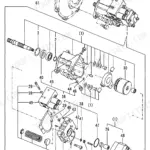
| Hyd. Oil Pump & Pump Mount | 0-0 |
| Hyd. Oil Tank | 0-0 |
| Bucket | 0-0 |
| Bucket Cylinder | 0-0 |
| Boom Cylinder | 0-0 |
| Swing Cylinder | 0-0 |
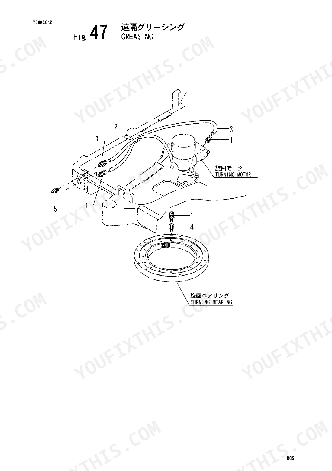
| Greasing | 0-0 |
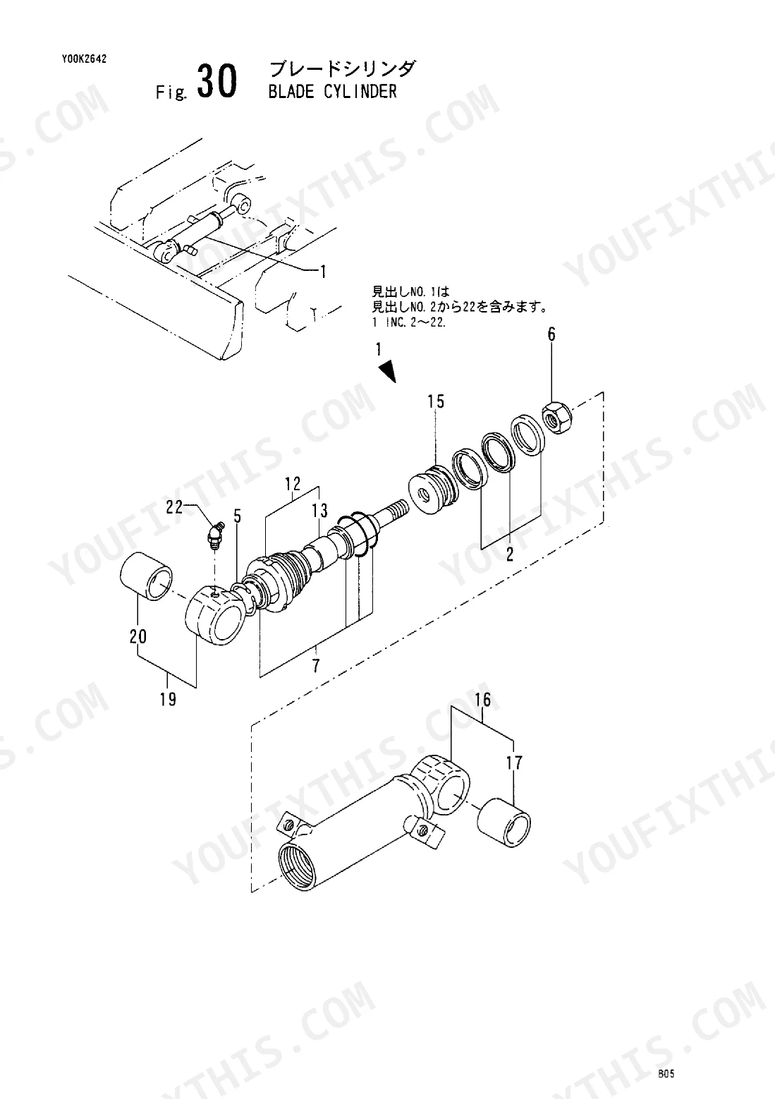
| Blade Cylinder | 0-0 |
| Blade | 0-0 |
| Hyd. Oil P. T. O | 0-0 |
| Driving Motor | 0-0 |
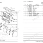
| Engine Mount & Engine Accessory | 0-0 |
| Silencer | 0-0 |
| Fuel Tank & Fuel Line | 0-0 |
| Turning Motor | 0-0 |
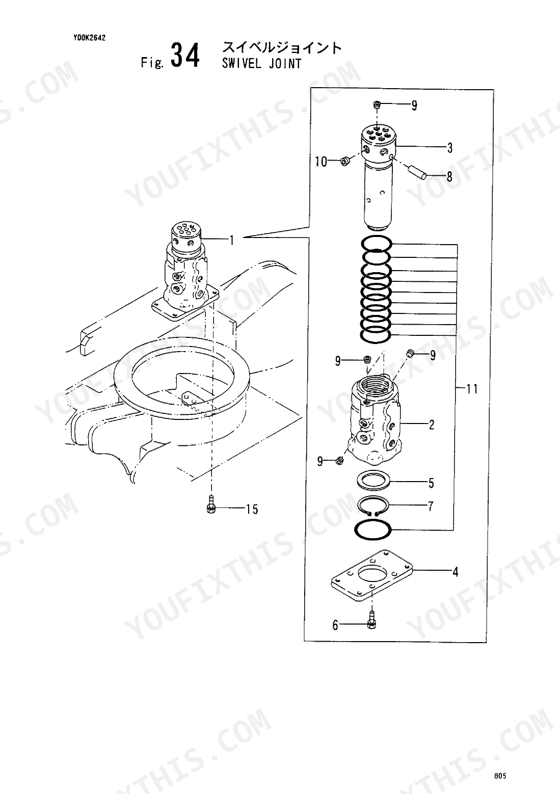
| Swivel Joint | 0-0 |
| Selector Valve | 0-0 |
| Frame | 0-0 |
| Turning Driving Equipment | 0-0 |
| Operation Lever Stopper | 0-0 |
| Idler, Track Roller & Crawler | 0-0 |
Quick Reference Specifications
| Specification | Value | Page |
|---|---|---|
| Fuse rating | 10A | p. 33 |
Yanmar B05 G / P / Y (Crawler Backhoe) Common Problems This Manual Covers
Yanmar B05 backhoe blew a fuse after electrical fault; need correct fuse part number and amperage rating
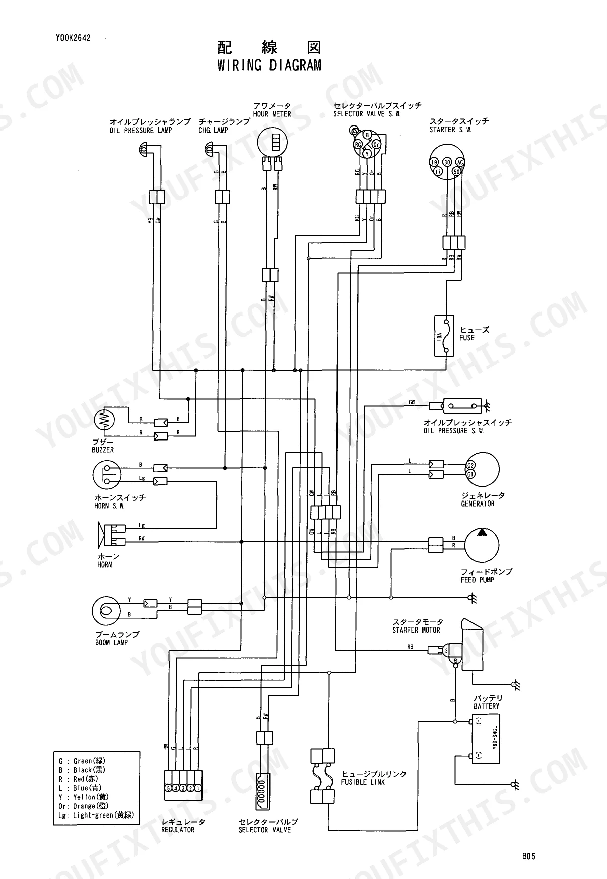
Trace the blown circuit on the wiring diagram to confirm which line is affected. The machine runs a 10A fuse (page 33); match that rating to the correct fuse part number in the parts number list. Confirm your model variant on page 1 before ordering, as the L70ADEB designation may reference a different part number than the B05 family.
Manual Section: Wiring DiagramHydraulic hose weeping at fitting; exploded view shows multiple similar assemblies with no clear part number visible
Open the hydraulic parts diagram and match each hose assembly to its assigned callout number in the exploded view. Cross-reference those callout numbers in the parts number list. The B05 has a max ground-level reach of 2370 mm (page 2), meaning boom and arm hose lengths are model-specific; verify your serial range on page 1 before placing the order.
Manual Section: Hydraulic Parts DiagramSprocket is visibly worn but the parts list shows several assemblies; unclear which callout matches this undercarriage
Locate the sprocket assembly in the drivetrain parts diagram and note the callout number. Confirm tooth count at page 37 before ordering; the replacement must match the original 11-tooth configuration. Cross-reference the callout number in the parts number list, then check your model variant on page 1, as undercarriage configurations differ between the B05 and L70ADEB.
Manual Section: Drivetrain Parts DiagramJoystick harness connector is corroded and needs replacement; can't identify the correct part number from the wiring diagram
Pull up the wiring diagram and trace the joystick circuit to identify the connector designation. Confirm the fuse protecting that circuit is 10A at page 33 so the replacement connector is specified for the correct load. Match the connector designation to the parts number list, then cross-reference physical mounting hardware in the cab interior diagram.
Manual Section: Wiring DiagramPins and bushings at the boom-to-stick joint need replacing; multiple callout numbers in the exploded view are confusing
Open the boom and attachment parts diagram and identify each pin and bushing by its individual callout number; the exploded view separates them even when they share an assembly group. Cross-reference callout numbers in the parts number list. The standard bucket is rated at 0.011 m³ (page 2) on the B05 base model; verify your serial range on page 1 before ordering to ensure pin dimensions match.
Manual Section: Boom & Attachment Parts DiagramNeed to order touch-up paint but the color code and paint part number for this serial number range aren't clear
Match your serial number against the model and effective machine number columns on page 3 to identify the correct Munsell color code for each body section. Locate the corresponding paint part number on page 4. At 2400 mm long and 690 mm wide (page 2), this machine has substantial painted surface area; confirm that separate part numbers are ordered for each color zone shown on page 4.
Manual Section: Vehicle Painted Color p. 3Frequently Asked Questions
How do I find the wiring diagram?
The wiring diagram is located on page 7 of the manual, under the section titled "WIRING DIAGRAM". This diagram illustrates the connections for components such as the OIL PRESSURE LAMP, CHARGE LAMP, FUSE, BATTERY, and STARTER MOTOR. p. 7
Is this Yanmar B05 manual a download or a disc?
Immediate download of the complete 110-page searchable Parts Catalog (2 MB). Access it on any device, from a laptop at your desk to a phone in the field.
Can I print a copy of this Yanmar B05 Parts Catalog for the shop?
Zero restrictions. The PDF is DRM-free. Print whatever sections you need to take out to the shop. Standard letter or A4 paper works.
Can I find hydraulic circuit diagrams in this Yanmar B05 manual?
Yes, this Yanmar B05, B05 G, B05 P, B05 Y, B05 G EX, B05 G AY, L70ADEB Parts Catalog includes a hydraulic system diagram.
Reviews
There are no reviews yet.