


![Case 40 Series D Repair Manual [Crawler Excavator]](https://youfixthis.com/wp-content/uploads/2012/02/Manual_Download-300x300.jpg)
Part of the Case Repair Manuals.
This is the complete factory repair manual for the Case 521D wheel loader. It is organized into the standard Case service groups, General, Engines, Fuel System, Electrical, Steering, Power Train, Brakes, Hydraulics, and Mounted Equipment, and it includes the electrical and hydraulic schematic foldouts. Engine and radiator removal, stall tests, and specifications are covered here, while internal engine and fuel-injection repair is referred to the separate Case Engine Service Manual. Many sections carry a second version for machines with product identification number JEE0135501 and above, so both early and later 521D builds are documented with grounded specifications, pressure checks, and step-by-step removal and installation procedures.
What's Inside This Case 521D Repair Manual
| System | Pages | Key Topics |
|---|---|---|
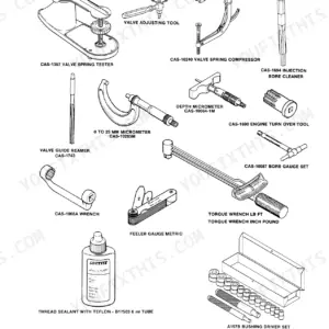
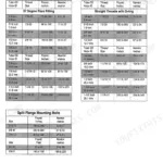
| General | Standard Torque Specifications, Fluids and Lubricants, Metric Conversion Chart, Loctite Product Chart | |
| Engines | Engine and Radiator Removal and Installation, Engine and Radiator Removal and Installation P.I.N. JEE0135501 and Above, Stall Tests, For Engine Repair, See the Engine Service Manual | |
| Fuel System | For Fuel System Repair, See the Engine Service Manual | |
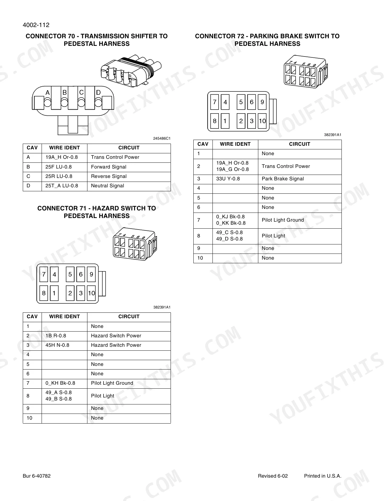
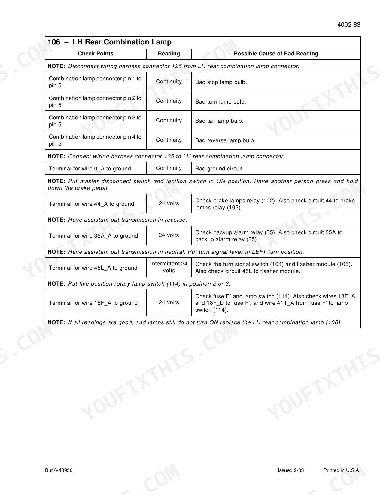
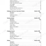
| Electrical | Removal and Installation of Starter and Alternator, Electrical Specifications and Troubleshooting, Electrical Specifications and Troubleshooting P.I.N. JEE0135501 and Above, Batteries, Information and Diagnostic Center, Alternator - 65 Ampere, Alternator - 45 Ampere | |
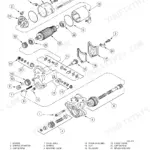
| Steering | Removal and Installation of Steering Components, Steering Specifications, Pressure Checks, And Troubleshooting, Steering Control Valve, Steering Priority Valve, Steering Cylinders, Center Pivot, Auxiliary Steering Motor and Pump | |
| Power Train | Removal and Installation of Power Train Components, Transmission Specifications, Pressure Checks, And Troubleshooting, Transmission, Front and Rear Axle, Front and Rear Axle P.I.N. JEE0135501 and Above, Drive Shafts, Center Bearing, And Universal Joints, Wheels and Tires, Transmission Control Valve | |
| Brakes | Removal and Installation of Brake Components, Hydraulic Brake Troubleshooting, Brake Accumulators, Parking Brake | |
| Hydraulics | Removal and Installation of Hydraulic Components, Hydraulic Specifications, Troubleshooting, And Pressure Checks, Cleaning the Hydraulic System, Cylinders, Coupler Solenoid Locking Valve, Pilot Pressure Accumulator and Ride Control Accumulator | |
| Mounted Equipment | Pedals and Levers, Air Conditioning Troubleshooting and System Checks for Systems with HFC-134a Refrigerant, Air Conditioner System Service, Removal and Installation of Air Conditioning Components for Systems with HFC-134a Refrigerant, Loader, ROPS Cab and ROPS Canopy, Cab Glass Installation | |
| Schematic Foldouts | Electrical Schematic Foldouts and Hydraulic Schematic Foldout, Electrical Schematic Foldouts and Hydraulic Schematic Foldout P.I.N JEE0135501 and Above |
Quick Reference Specifications
| Specification | Value | Page |
|---|---|---|
| Engine | ||
| Low idle speed | 1020 to 1080 rpm | |
| Full throttle, no load | 2220 to 2280 rpm | |
| Engine oil capacity with filter change | 10.5 L (11 qt) | |
| Torque Converter | ||
| Torque converter stall speed | 1930 to 2090 rpm | |
| Torque converter oil operating temperature | 82 to 104 C (180 to 220 F) | |
| Hydraulic System | ||
| Hydraulic system stall speed | 1945 to 2255 rpm | |
| Hydraulic reservoir refill with filter change | 68.5 L (18 gal) | |
| Hydraulic oil operating temperature | 51 to 79 C (125 to 175 F) | |
| Power Train / Hydraulics | ||
| Combined torque converter and hydraulic stall speed | 1395 to 1705 rpm | |
| Cooling System | ||
| Cooling system capacity | 34.1 L (9 gal) | |
Case 521D Common Problems This Manual Covers
Loader will not move forward or reverse, with the buzzer and cluster alarms on after start-up
Work the Power Train and Hydraulics troubleshooting first: run the transmission pressure checks and the torque-converter and hydraulic stall tests against spec, then inspect the transmission control valve. If pressures are in range, move to the Electrical group and check the Information and Diagnostic Center and harness for the fault triggering the alarm. This isolates a hydraulic, transmission, or electrical cause before removal.
Manual Section: Power TrainSlow or weak loader hydraulics and long cycle times
Use the Hydraulics group specifications, troubleshooting, and pressure checks. Verify main and pilot pressures and the ride-control and pilot-pressure accumulators, and check the coupler solenoid locking valve. Confirm the hydraulic oil is at the 51 to 79 C operating temperature before reading pressures, since cold oil skews the results.
Manual Section: HydraulicsSteering feels heavy, wanders, or the machine is hard to turn
Follow the Steering group: check steering specifications and pressure checks, then the steering priority valve, steering control valve, and center pivot. The auxiliary steering motor and pump are also covered for the emergency-steering circuit. Confirm priority-valve pressure before replacing steering components.
Manual Section: SteeringTrapped hydraulic pressure makes engine or component removal difficult and unsafe
Follow the removal procedures in the Engines and Hydraulics groups exactly: relieve system pressure by loosening the hydraulic reservoir cap and cycling the controls, and engage the frame articulation lock before working between the frames. The manual's removal and installation steps call out each pressure-discharge point so lines are not opened under pressure.
Manual Section: EnginesFrequently Asked Questions
Does this manual cover engine internal repair, or just removal?
The Engines group covers engine and radiator removal and installation and stall tests for the 521D, but internal engine and fuel-injection repair is handled in the separate Case Engine Service Manual, which this repair manual points you to. Use this book for pulling the engine, the drivetrain, and everything around it.
My 521D will not move forward or reverse and the buzzer stays on. Where do I start?
Start in the Power Train and Hydraulics groups. Run the transmission and hydraulic pressure checks and stall-speed tests against the specification values, then check the transmission control valve and the electrical Information and Diagnostic Center. A pressure loss, a stuck control valve, or an electrical fault will each cause loss of drive with alarms, so measure before you tear anything down.
What are the fluid capacities and stall speeds for the 521D?
Cooling system holds 34.1 L (9 gal), engine oil is 10.5 L (11 qt) with a filter change, and the hydraulic reservoir refill is 68.5 L (18 gal) with a filter change. Low idle is 1020 to 1080 rpm and full throttle no-load is 2220 to 2280 rpm; torque-converter stall is 1930 to 2090 rpm and hydraulic stall is 1945 to 2255 rpm. The General and section specification pages list the full set.
Does it cover the later serial-number machines?
Yes. Several sections, including Engine and Radiator Removal, Electrical Specifications, and the Front and Rear Axle, carry a second version for P.I.N. JEE0135501 and Above, so both the early and later 521D builds are documented. Match your machine's product identification number to the correct section.
Are the electrical and hydraulic schematics included?
Yes. The manual includes full electrical schematic foldouts and a hydraulic schematic foldout (with a separate electrical foldout set for P.I.N. JEE0135501 and Above), so you can trace circuits and hydraulic flow end to end instead of guessing.
What do I get after purchasing this Case 521D manual?
A 1000-page Repair Manual in searchable PDF format (151 MB), available the moment you complete checkout. View on computer, tablet, or phone, with no shipping wait.
Can I print specific sections of this Case 521D Repair Manual?
Yes, print as many copies as you want, and there are no restrictions. Many mechanics print the section they need and bring it to the shop floor.


Reviews
There are no reviews yet.