


This Gehl service manual covers the CT6-18 and CT6-18 Turbo telescopic handlers. The CT6-18 runs the naturally aspirated Perkins 1104C-44 rated at 84 hp, and the Turbo runs the Perkins 1104C-44T at 101 hp. Its 580 pages take you through the whole machine: general information and specifications, full engine service, the transmission and its hydraulic circuit, the front and rear Dana axles, the hydraulics, and the electrical system.Each section combines specifications, procedures, and troubleshooting, with the torque values, pressures, and filter data a real repair needs. You can rebuild the engine to the listed torque figures, check transmission pressures, service the hydraulic steering unit, or plan filter changes from the part numbers and intervals in the manual. It is a searchable PDF you can read on any device or print for the shop, so download it once and keep it with the machine for every job.
What's Inside This Gehl CT6-18 TURBO, CT6-18 Manual
| System | Pages | Key Topics |
|---|---|---|
| General Information | 5-18 | Introduction, Engine Views, Engine Identification, Safety Precautions, Engine Lift Equipment, Viton Seals, Powerpart Recommended Consumable Products |
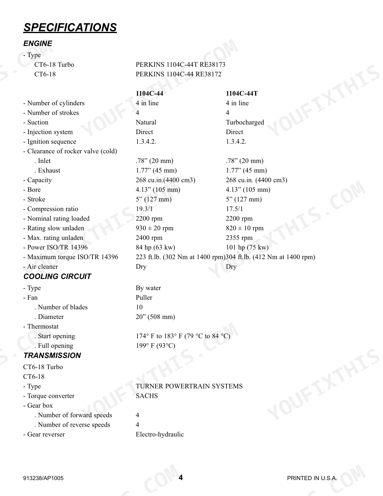
| Specifications | 33-66 | General Information, Introduction, Engine Views, Engine Identification, Safety Precautions, Engine Lift Equipment, Viton Seals, Powerpart Recommended Consumable Products |
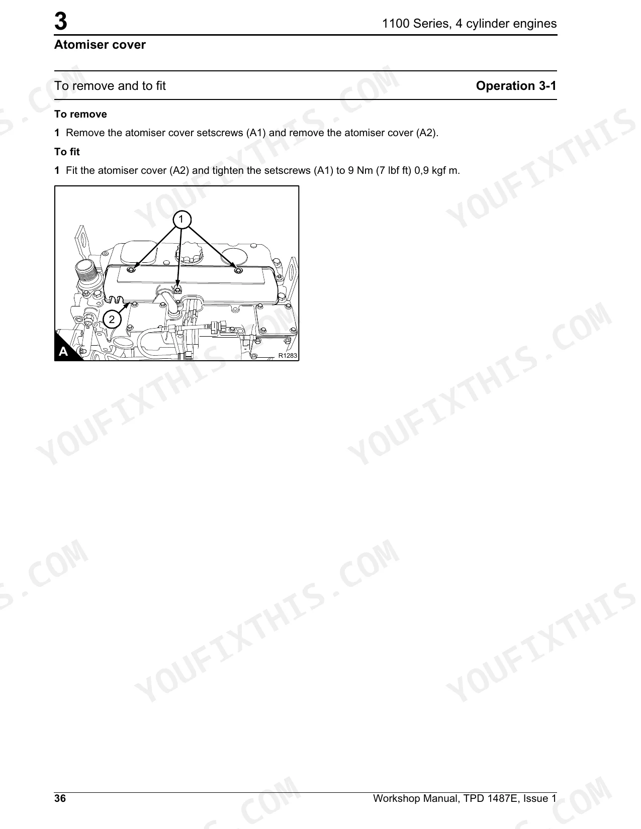
| Cylinder Head Assembly | 67-92 | General Description, Atomiser Cover, Rocker Cover, Rocker Assembly, Valve Tip Clearances, Valve Springs, Valves and Valve Springs |
| Crankshaft Assembly | 93-132 | Piston and Connecting Rod Assemblies, General Description, Big End Bearing, Piston and Connecting Rod, Piston Rings, Piston and Connecting Rod Assembly, Piston and Piston Rings, Connecting Rod |
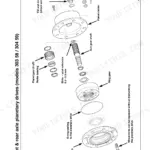
| Timing Case and Drive Assembly | 133-160 | General Description, Timing Case Cover, Mechanical Fuel Pump Gear, Electronic Fuel Pump Gear, Idler Gear and Hub, Heavy Duty Idler Gear Assembly, Camshaft Gear |
| Aspiration System | 161-188 | Engine Timing, Cylinder Block Assembly, General Description, Cylinder Block, Cylinder Bore, To Check the Valve Timing, Turbocharger Side Mounted |
| Fuel System | 189-232 | Lubrication System, General Description, Lubrication System Flow Diagram, Filter Canister, Filter Head, Sump, Dipstick Tube, Oil Strainer and Suction Pipe |
| Electrical Equipment | 233-282 | Cooling System, General Description, Coolant Flow Diagram, Thermostat, Coolant Pump, Fan, Fan Drive, Lubricating Oil Cooler |
| Special Tools | 283-294 | Auxiliary Equipment, Power Steering Pump, Exhauster |
| Transmission | 295-348 | Gear Box and Converter, Gear Box, Transmission Hydraulic Circuit, Transmission Hydraulic Principal Circuit, Transmission Maintenance, Pressure Checking |
| Axles | 349-514 | Introduction |
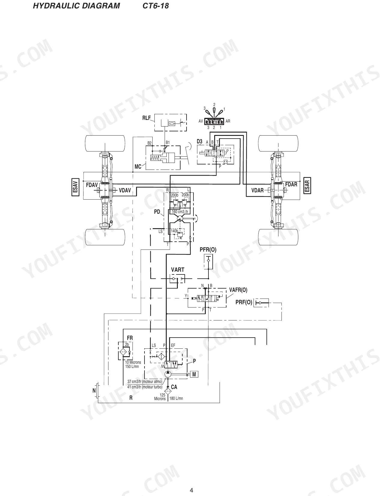
| Hydraulics | 515-564 | Exploded View: Ospb, Ospc / Ospf, Tools, Dismantling, Assembling, Max. Tightening Torque and Hydraulic Connections, Trouble Shooting, CT6-18 Hydraulic Diagram |
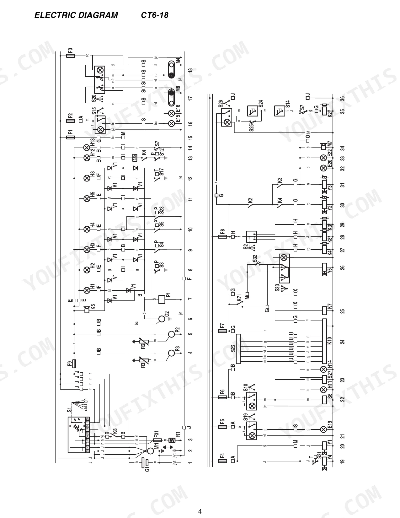
| Electrical | 565-580 | Electric Diagram, Contents (CT6-18: Electric Diagram, Turbo Electric Diagram) |
Quick Reference Specifications
| Specification | Value | Page |
|---|---|---|
| Hydraulic connection torque (M18 x 1,5 with O-ring) | 5 daNm (440 lbf in) | p. 547 |
| Hydraulic seals replacement | Replace all seals and washers | p. 533 |
| Hydraulic Return Oil Filter Cartridge part number | 217785 | p. 16 |
| Hydraulic Return Oil Filter Cartridge change interval | 500 H | p. 16 |
| Fuel Filter Cartridge part number | 219994 | p. 16 |
| Fuel Filter Cartridge change interval | 500 H | p. 16 |
| Dry Air Filter Cartridge part number | 219980 | p. 16 |
| Dry Air Filter Cartridge clean interval | 50 H* | p. 16 |
| Battery specification | 12 V - 145 Ah - 950 A EN | p. 9 |
| Starter specification | 12 V - 3,0 kW | p. 9 |
| Starter type | Denso E95RL | p. 9 |
| Front and Rear Tires pressure | 38 PSI | p. 10 |
Gehl CT6-18 TURBO, CT6-18 Common Problems This Manual Covers
Machine will not start
No start or intermittent starting often traces to the battery, starter, or a safety interlock. The Electrical section provides the electric diagrams for both the CT6-18 and the Turbo.
Manual Section: Electrical p. 565Boom will not lift or extend
A boom that will not lift or respond points to fluid condition, a leak, or a valve or pump fault. The Hydraulics section covers the steering unit, tightening torques, troubleshooting, and the hydraulic diagram.
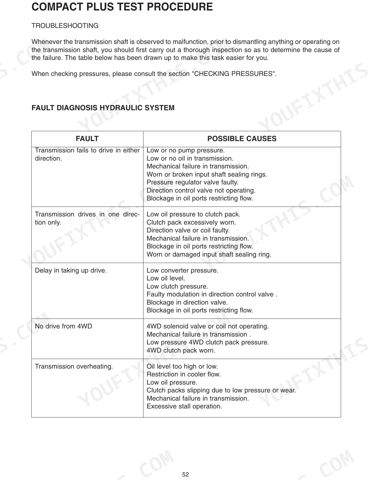
Manual Section: Hydraulics p. 515Transmission overheating
Transmission overheating can stem from an oil level that is too high or too low. The Transmission section covers the hydraulic circuit, maintenance, and pressure checking.
Manual Section: Transmission p. 295Poor steering or loss of traction
Worn axle components or drivetrain wear show up as poor steering and lost traction. The Axles section covers front and rear Dana axle service.
Manual Section: Axles p. 349Engine oil leaks or high hour wear
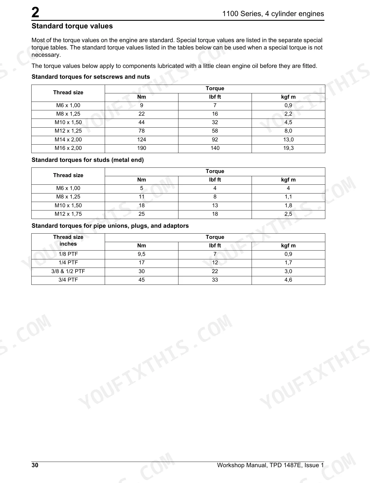
High hours bring seal, valve, and bearing wear on the Perkins diesel. The Engine section carries the full teardown with torque values such as the 245 Nm main bearing setscrews.
Manual Section: Engine p. 19Clogged filters and missed intervals
Skipped filter changes lead to restricted flow and contamination. The General Information section lists filter cartridge part numbers and change intervals.
Manual Section: General Information p. 5Frequently Asked Questions
Which machines and engines does this cover?
It is the Gehl service manual, publication 913238, for the CT6-18 and CT6-18 Turbo telescopic handlers. The CT6-18 uses the Perkins 1104C-44 at 84 hp and the Turbo uses the 1104C-44T at 101 hp.
Where are the engine torque specs?
The Engine section lists standard and specific torque values; for example, the main bearing setscrews torque to 245 Nm (180 lbf ft). Individual procedures state their own figures. p. 19
Does it list hydraulic filter part numbers?
Yes. The General Information section lists the hydraulic return oil filter cartridge (part 217785, change every 500 hours) along with the tank filter cap and suction strainer. p. 5
How do I get the file after buying?
You download the PDF straight after checkout. There is no shipping and no wait; the file is yours to keep and open on any device.
How will I receive this Gehl CT6-18 TURBO, CT6-18 Service Manual?
A 580-page Service Manual in searchable PDF, ready to download the moment checkout completes. Open it on a computer, tablet, or phone, with no shipping wait.
Are there any print restrictions on this Gehl CT6-18 TURBO, CT6-18 manual?
Yes. The PDF carries no DRM, so you can print any page or section you need for the shop. It works with any standard printer.
Does this Gehl CT6-18 TURBO, CT6-18 Service Manual have electrical diagrams?
Yes. You'll find full electrical schematics with wire routing diagrams, connector identification, and circuit descriptions.


Reviews
There are no reviews yet.