


This Gehl CT7-23 Turbo service manual is the factory workshop reference for the 101 hp telescopic handler built around the Perkins 1104C-44T turbocharged diesel. Across 832 pages it walks through the whole machine: engine teardown and rebuild, the Turner powertrain transmission and gearbox, the front and rear Dana axles, the hydraulic servo brakes, the boom and its cylinders, the full hydraulic circuit, the wiring, and the air conditioning unit.Every section carries removal, disassembly, inspection, and reassembly steps with the torque values, pressures, and clearances the repair actually needs. Whether you are chasing a dead auxiliary hydraulic circuit, adjusting the parking brake, or pulling the transmission, you can find the exact procedure and specification instead of guessing. The manual is a searchable PDF you can read on any device or print at the bench, so download it once and keep it with the machine.
What's Inside This Gehl CT7-23 TURBO Manual
| System | Pages | Key Topics |
|---|---|---|
| General Information | 5-14 | Introduction, Engine Views, Engine Identification, Safety Precautions, Engine Lift Equipment |
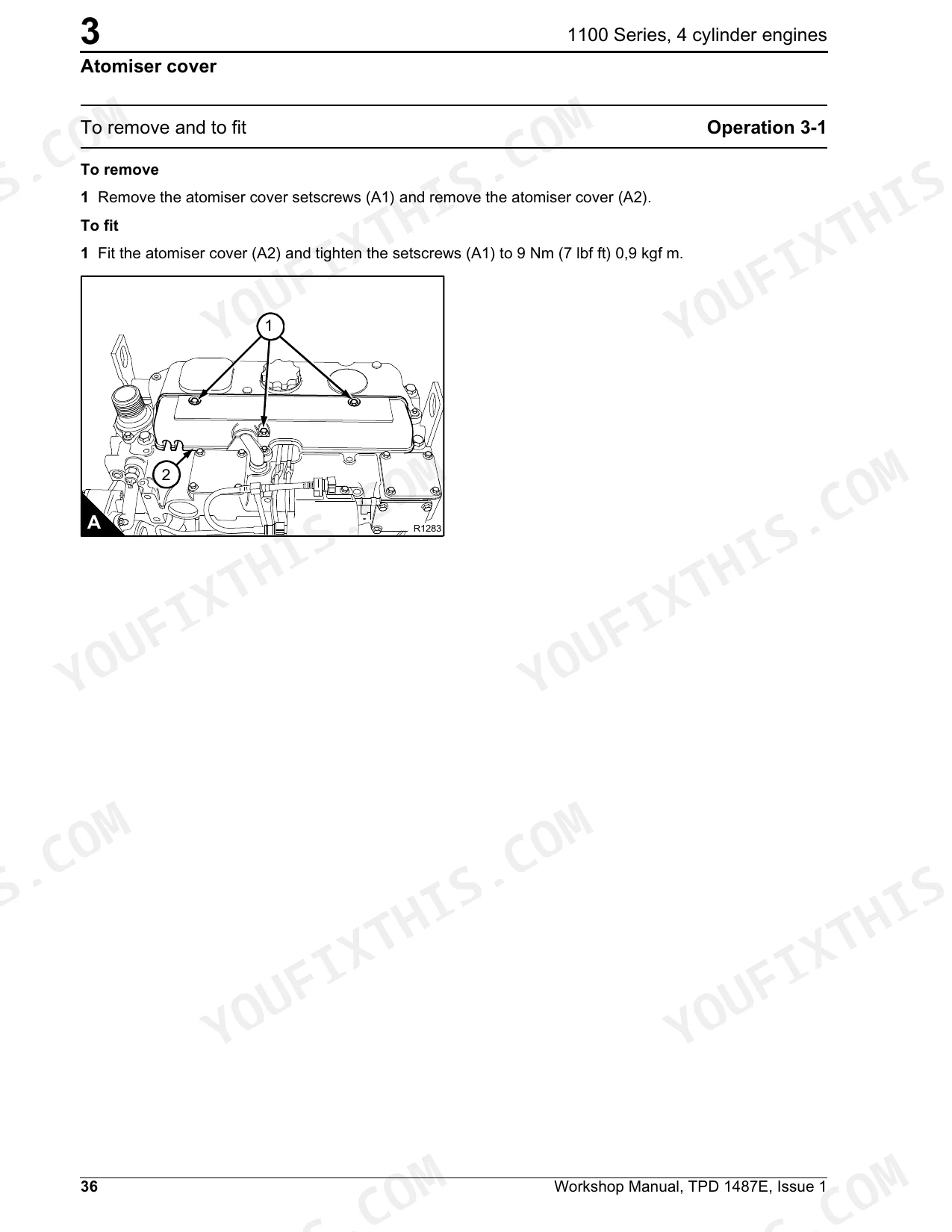
| Engine | 15-290 | Cylinder Head Assembly (Viton Seals, Atomiser Cover, Powerpart Recommended Consumable Products, Rocker Cover) |
| Fuel System | 291-294 | Fuel Sender Assembly, Procedure |
| Engine Cooling System | 295-298 | Fan Belt Adjustment Procedure, New Belt, Securing Ring Removal and Fitting Procedure, Alternator Belt Tension / Hydraulic Pump Adjustment (Procedure, Check) |
| Transmission and Gearbox | 299-392 | Removal of the Transmission, Gear Box and Converter, Gear Box (Details, Mechanism Details - Gears, Electrical Control Valve Details), Transmission Hydraulic Circuit |
| Axle Assembly | 393-572 | Removal of the Front Axle Assembly, Removal of the Rear Axle with Removable Axle Support, Removal of the Rear Axle Assembly Bracket |
| Brakes | 573-592 | Removal of the Parking Brake Pads (Reassembly of the Parking Brake Pads, Adjustment of the Parking Brake), Bleeding the Brake Circuit (Tooling Required, Procedure) |
| Boom | 593-618 | Removal of the Entire Jib, Adjustment and Immobilization of the Jib Wear Pads, Removal of the Paired Hoses in the Jib, Removal of the Tilting Cylinder, Removal of the Carriage |
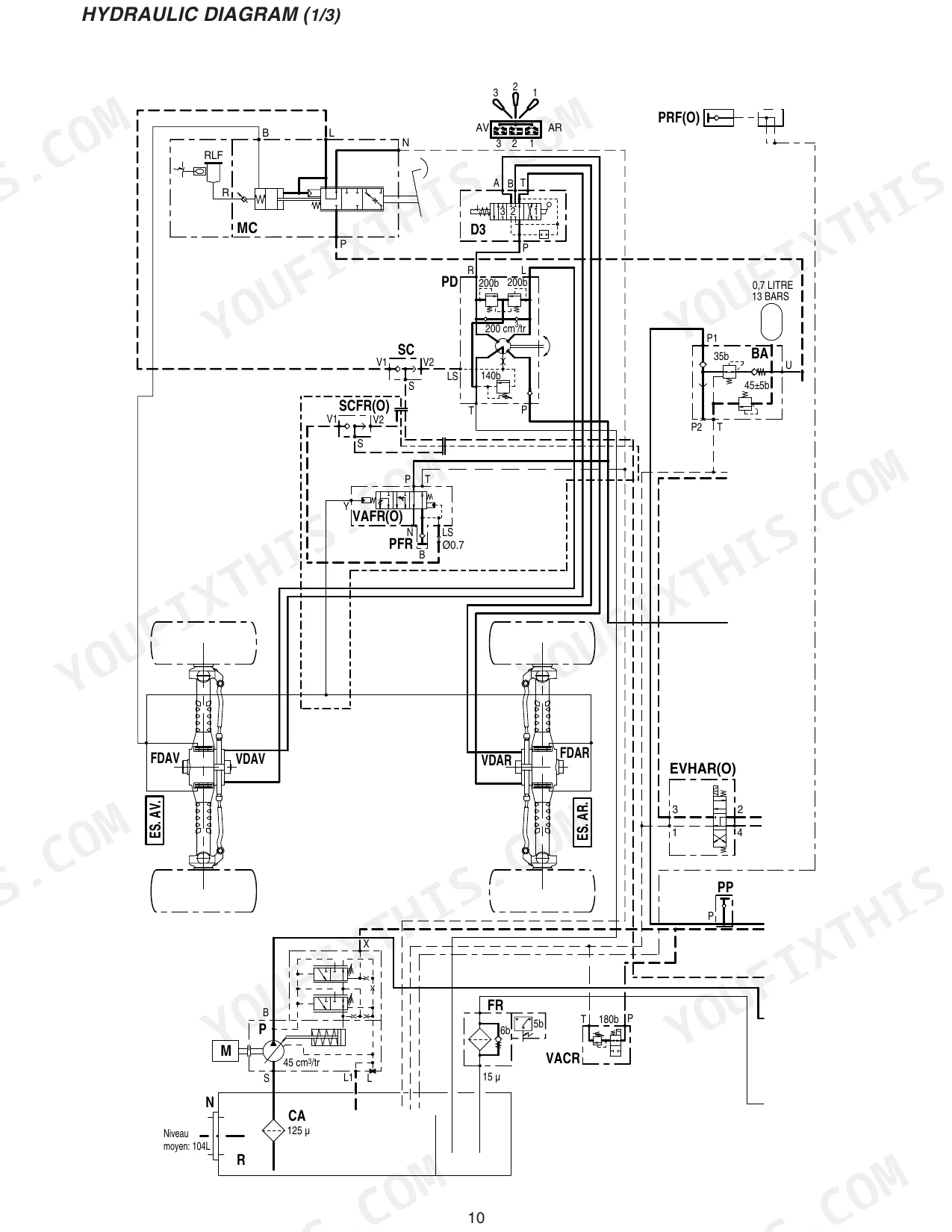
| Hydraulics | 619-718 | Introduction (Preface, Safety Instructions), Trouble-Shooting, Basic Rules, Removing / Remounting the Sx 14 Bloc (Removing the Sx 14 Block, Remounting the Sx 14 Block) |
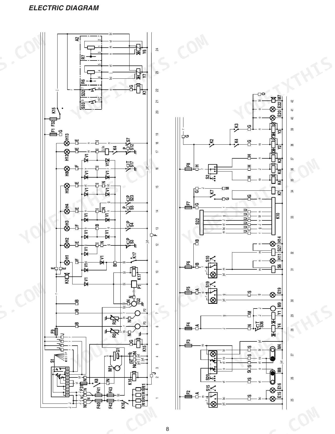
| Electrical | 719-790 | Electric Diagram (Principle Electric Circuit, Colour Coding, Connector, Electrics Components), Plate Electric Diagram (Location and Description of the Disk) |
| Air-Conditioning | 791-832 | Air Conditioning Unit Operating Principle, Instructions for Starting Up the Production Unit, Dealer Starting Up Instructions (Formation Client), Customer Use Manual |
Quick Reference Specifications
| Specification | Value | Page |
|---|---|---|
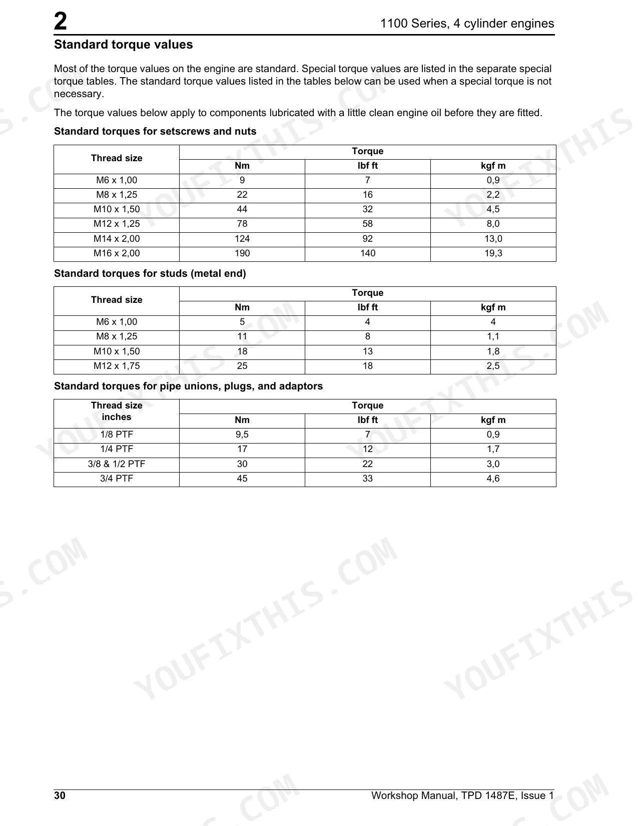
| Standard torque for M6 x 1.00 setscrews and nuts | 9 Nm | p. 58 |
| Electrohydraulic actuation module (EMS module) mounting screw torque | 15 ± 1 N.m. | p. 710 |
| Electrohydraulic actuation module mounting screw torque | 15 ± 1 N.m. | p. 710 |
| Positioning piston thread torque (electrohydraulic actuation module) | 10 ± 1 N.m. | p. 710 |
| Regulation unit guide / plunger replacement kit | kit | p. 764 |
| Minimum supply voltage for proportional control unit (when proportional functions have no movement) | 9V | p. 707 |
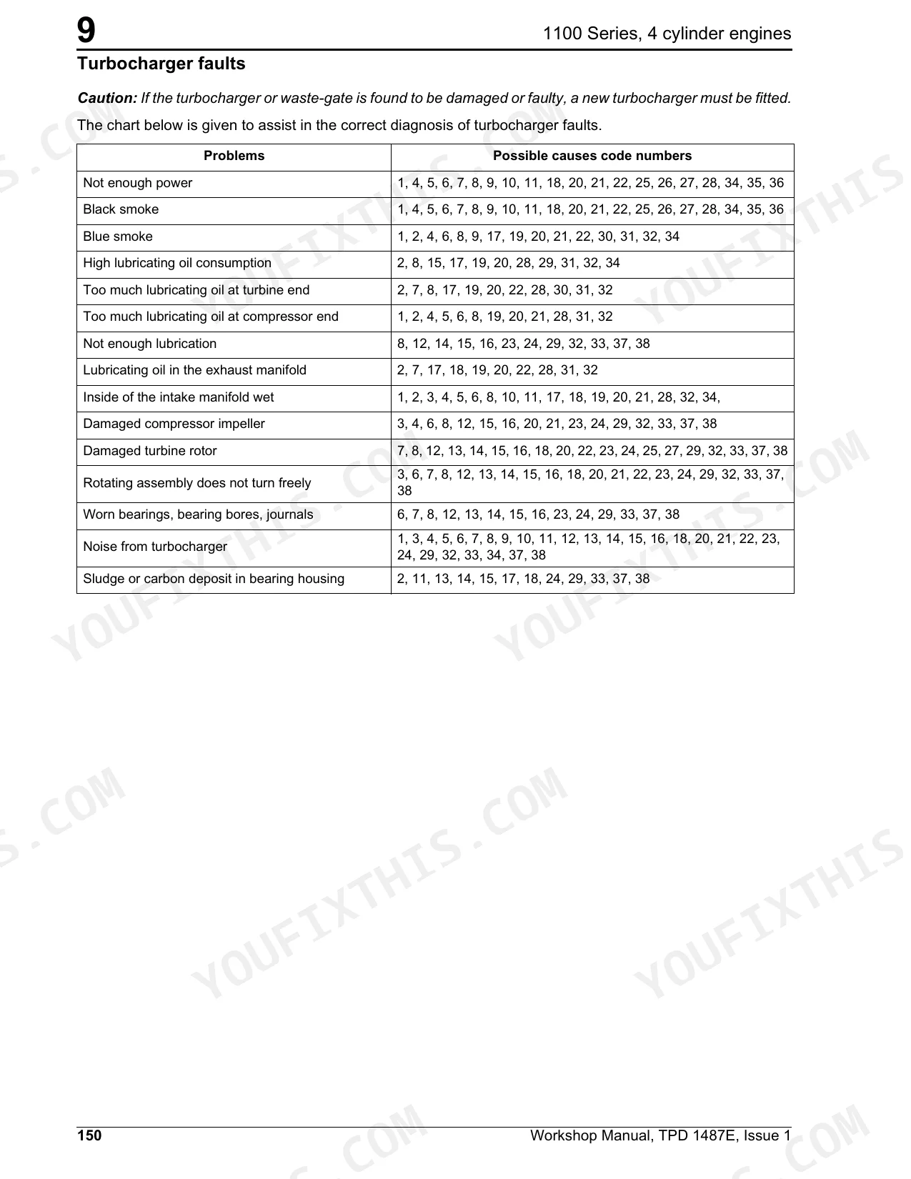
| Probable cause for sudden or irregular movement on all proportional functions | Protection filter partially sealed. | p. 707 |
| Transmission bearings replacement interval | over 1500 hours | p. 334 |
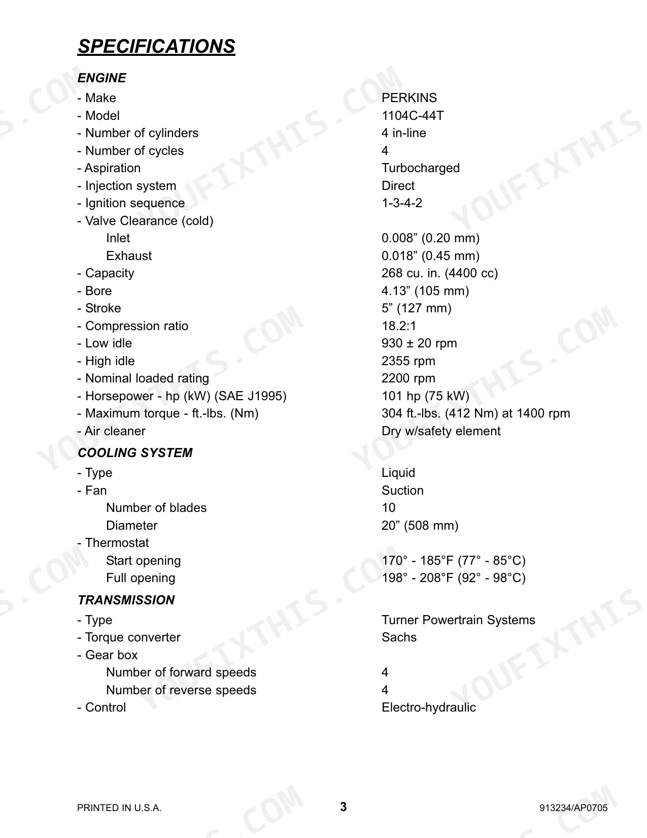
| Engine Horsepower | 101 hp (75 kW) | p. 7 |
| Engine Maximum Torque | 304 ft.-lbs. (412 Nm) at 1400 rpm | p. 7 |
| Engine Oil Capacity | 11-1/2 qts. (11 liters) | p. 13 |
| Hydraulic Oil Tank Capacity | 33 gal. (125 liters) | p. 13 |
Gehl CT7-23 TURBO Common Problems This Manual Covers
Auxiliary hydraulics stop working
Owners report the aux hydraulic circuit dropping out, so hydraulic latching pins and attachments will not operate. The Hydraulics section covers the SX 14 valve block and circuit troubleshooting to trace the fault.
Manual Section: Hydraulics p. 619Solenoid or wiring fault in aux circuit
Forum advice points to a failed solenoid as the first item to test when attachment functions go intermittent. The Electrical section documents the circuit, connectors, and components involved.
Manual Section: Electrical p. 719Weak transmission shifting or pressure
Low oil pump pressure or worn control valves cause poor shifting through the four speed powershift gearbox. The Transmission and Gearbox section gives removal and pressure checking procedures.
Manual Section: Transmission and Gearbox p. 299Parking brake will not hold
Worn parking brake pads or an out of adjustment lever let the machine creep on a slope. The Brakes section covers pad replacement, adjustment, and bleeding the brake circuit.
Manual Section: Brakes p. 573Boom drift or worn wear pads
Play in the jib or a leaking tilt cylinder shows up as boom drift and sloppy fork movement. The Boom section covers wear pad adjustment and cylinder removal.
Manual Section: Boom p. 593Engine oil leaks or low power
High hours bring cylinder head, valve, and seal wear on the Perkins 1104C-44T. The Engine section carries the full teardown with specifications and torque values.
Manual Section: Engine p. 15Frequently Asked Questions
Which machine and engine does this manual cover?
It is the factory service manual for the Gehl CT7-23 Turbo telescopic handler, publication 913234, powered by the Perkins 1104C-44T turbocharged four cylinder diesel rated at 101 hp (75 kW).
Where are the torque specifications?
The Engine section lists standard and specific torque values; for example, the standard torque for M6 setscrews and nuts is 9 Nm on page 58. Individual procedures also state their own torque figures where needed. p. 15
Does it help me fix dead auxiliary hydraulics?
Yes. The Hydraulics section includes troubleshooting plus the SX 14 valve block removal and refitting steps, the usual place to start when latching pins or attachments stop working. p. 619
How do I get the file after buying?
You download the PDF straight after checkout. There is no shipping and no wait; the file is yours to keep and reopen on any device.
How will I receive this Gehl CT7-23 TURBO Service Manual?
Delivery is instant: an 832-page searchable PDF you download right away. It opens on any device, so you can pull it up on your phone while you're under the hood. No shipping, no waiting.
Is this Gehl CT7-23 TURBO Service Manual printable?
No restrictions at all. Print individual pages, full chapters, or the entire manual. The PDF is completely unlocked.
Can I find wiring schematics in this Gehl CT7-23 TURBO manual?
Complete wiring diagrams are included, covering all electrical circuits, harness routing, and connector pinouts for the Gehl CT7-23 TURBO.


Reviews
There are no reviews yet.