


This Service Manual covers the Gehl RS Series telescopic handlers: the RS6-42, RS8-42, RS8-44, RS10-44, RS10-55, and RS12-42, all built with the John Deere 4045T diesel engine. It is the factory manual, form number 913233, Revision C, and runs 498 pages.The manual is organized into numbered sections covering safety, specifications, the engine, electrical and battery systems, steering, transmission, front and rear axles, the full hydraulic system, and both three-section and four-section booms. You get schematics, torque charts, fluid capacities, testing and adjustment procedures, and step by step removal and installation instructions.With this PDF download an owner or independent mechanic can chase a no-start, fix a machine that will not go into gear, service the boom cylinders and chains, or rebuild a hydraulic cylinder using the same specifications the Gehl dealer relies on.
What's Inside This Gehl RS6–RS12 Series Manual
| System | Pages | Key Topics |
|---|---|---|
| Safety & Precautions | 5-20 | Safety Rules and Reminders, Decal Locations, New Decal Application, Frame and Boom Decals, Operator Station Decals, Pwp Equipped Unit Decals |
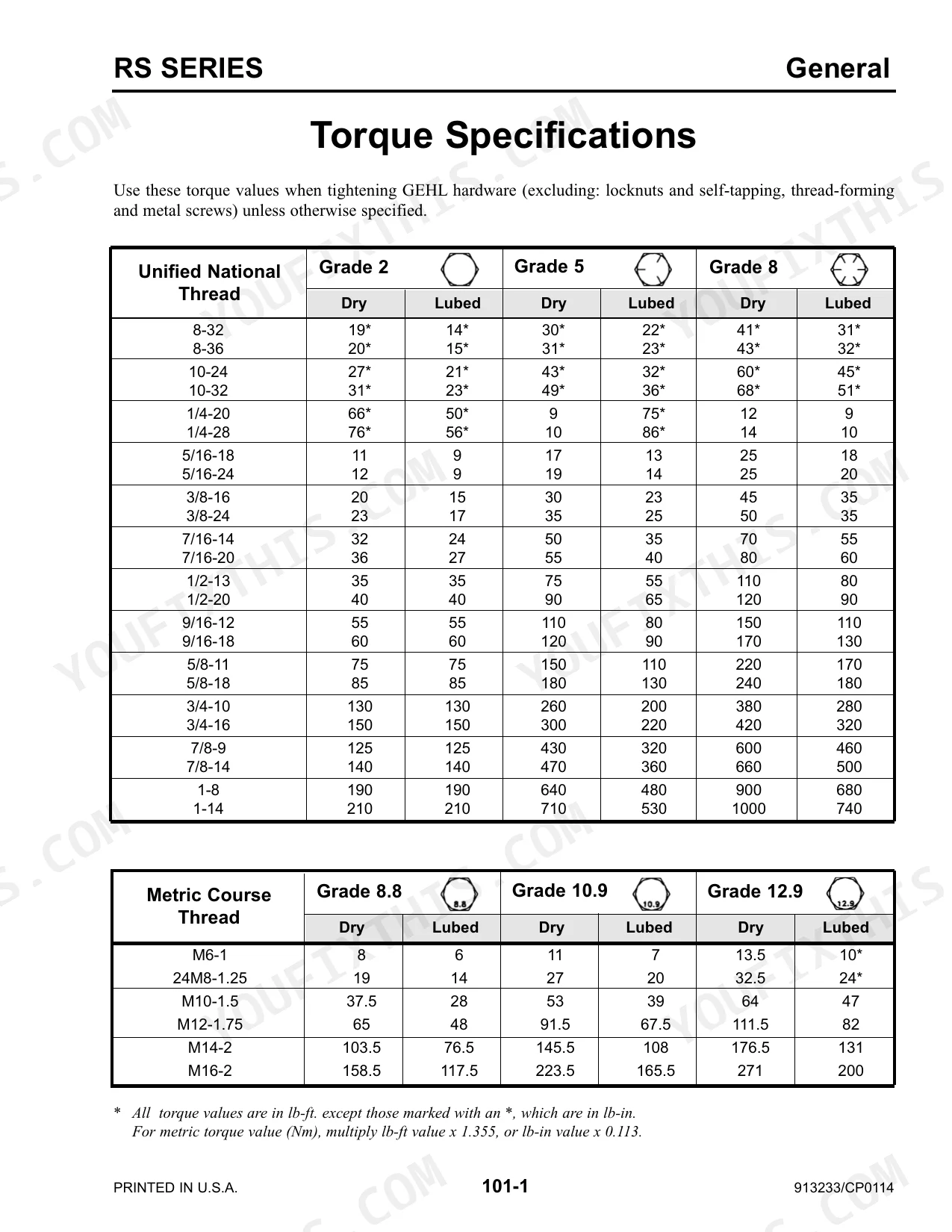
| Specifications & Torque Data | 21-40 | Sae Fastener Torque Chart, Metric Fastener Torque Chart, Hydraulic Tube and Fitting Torque Data, Indicator and Operation Symbols, Fluid Capacities and Types |
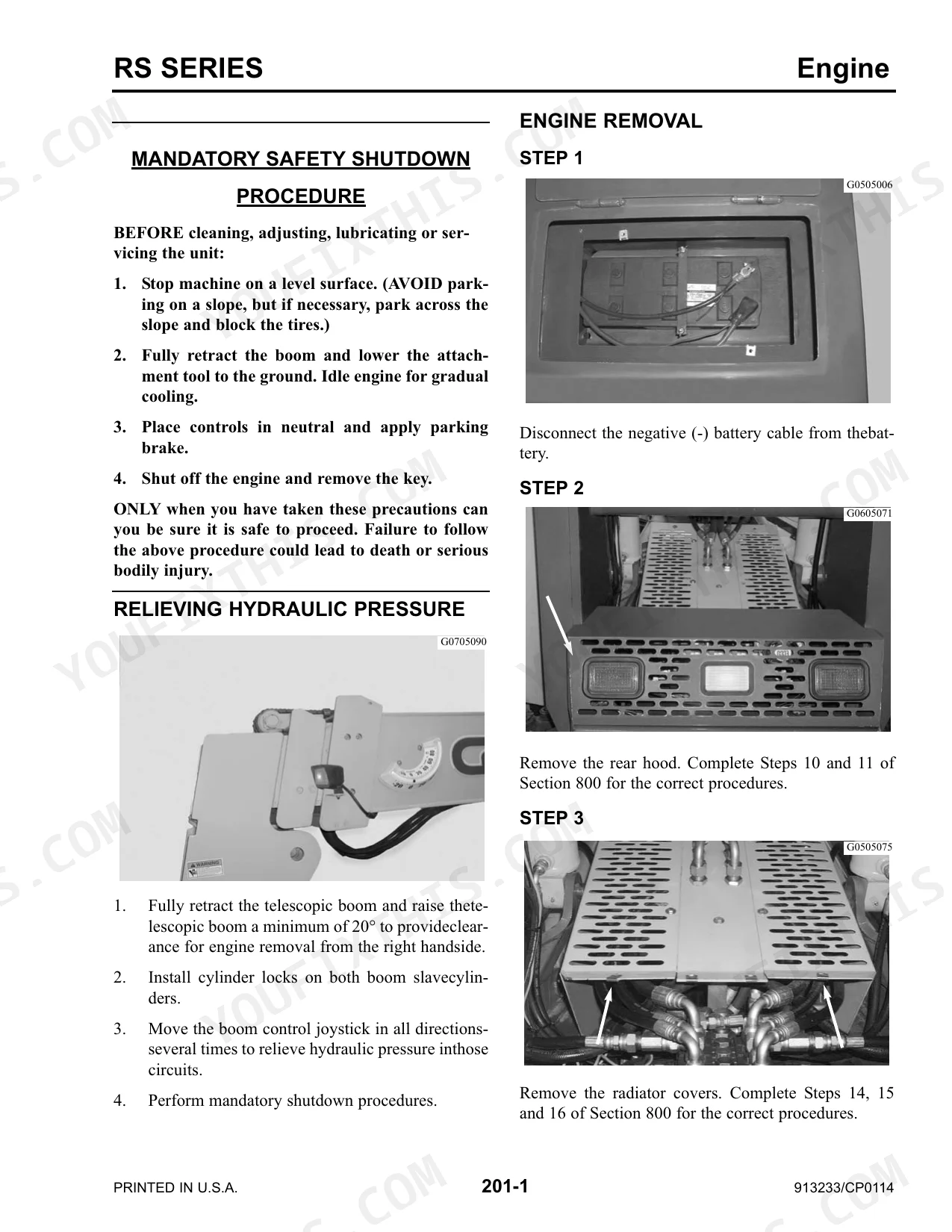
| Engine | 41-62 | Engine Removal, Engine Installation, Relieving Hydraulic Pressure |
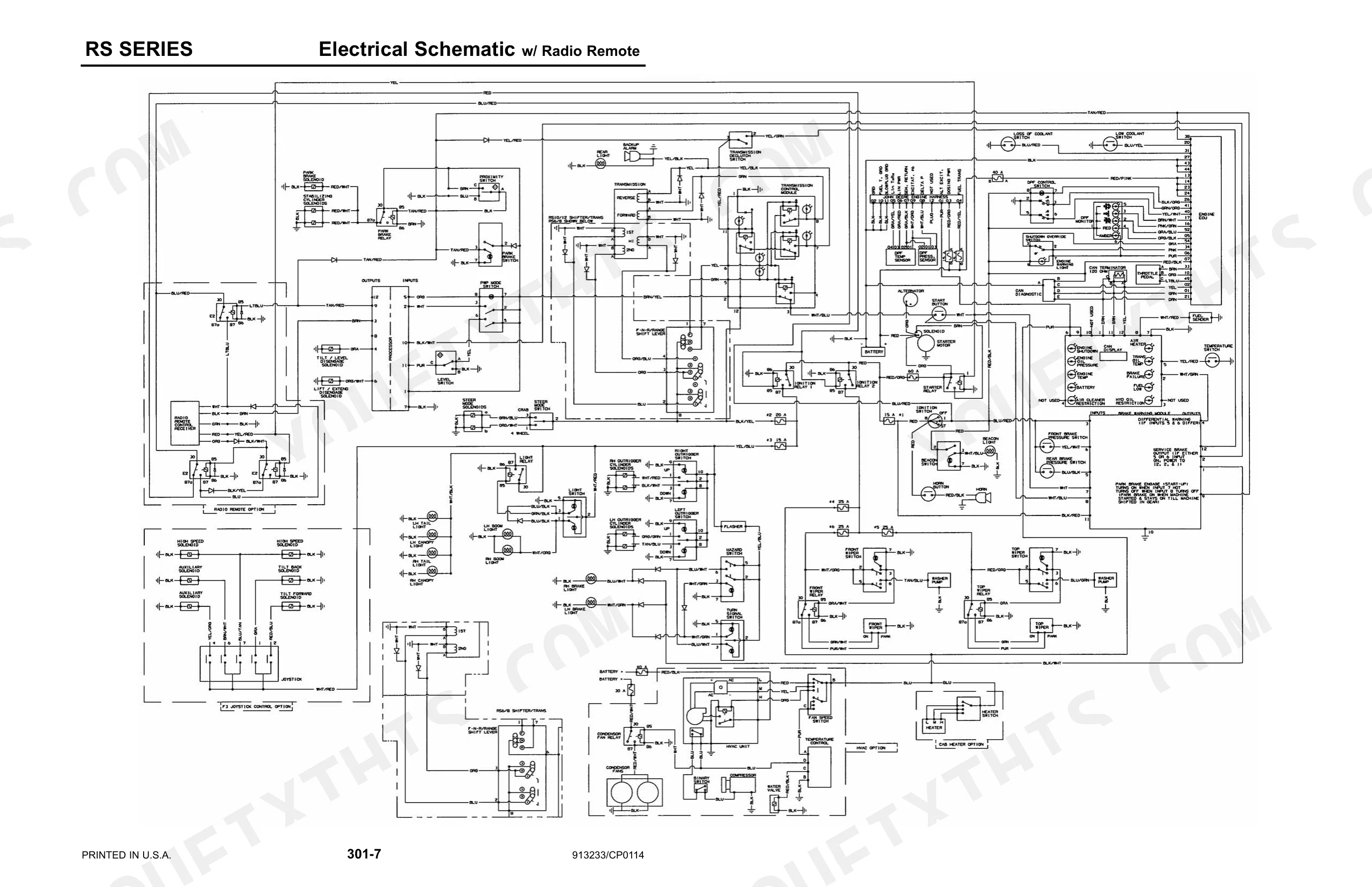
| Electrical & Battery | 63-92 | Instrument Panel and Bulb Replacement, Electrical Schematics, Battery Removal, Battery Installation |
| Steering, Transmission & Axles | 93-138 | Steering Control Valve Installation, Transmission Removal, Transmission Installation, Rear Axle Removal, Rear Axle Installation, Front Axle Removal, Front Axle Installation, Relieving Hydraulic Pressure |
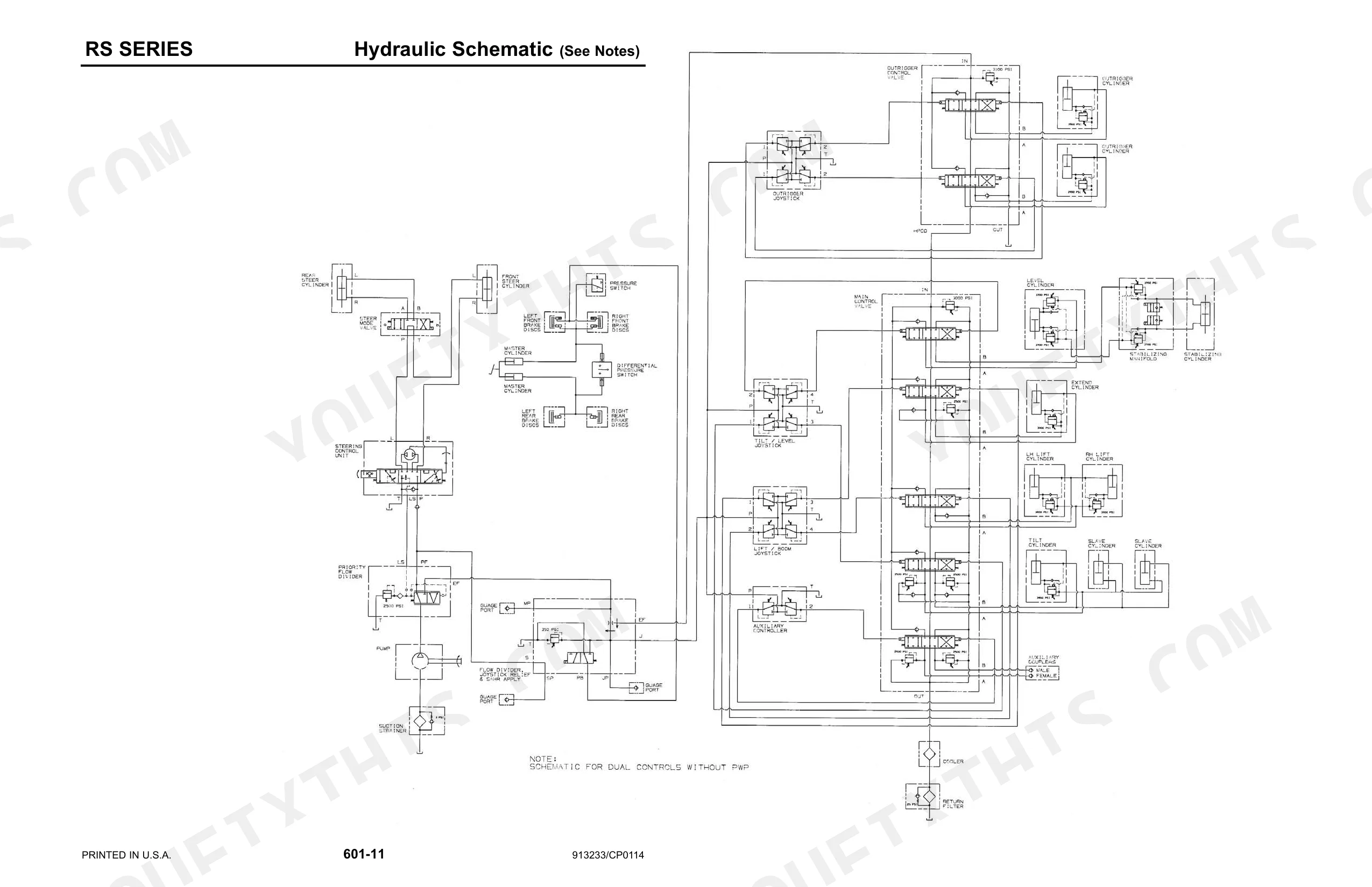
| Hydraulic System & Pump | 139-200 | Hydraulic Schematics, Testing and Adjustment Procedures, Hydraulic Specifications, Pump Removal, Pump Installation |
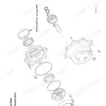
| Hydraulic Cylinders | 201-262 | Frame Leveling Cylinder, Tilt Cylinder, Cylinder Disassembly and Assembly, Stabilizing Cylinder Removal and Repair, Slave Cylinder, Lift Cylinder Removal and Adjustment, Relieving Hydraulic Pressure |
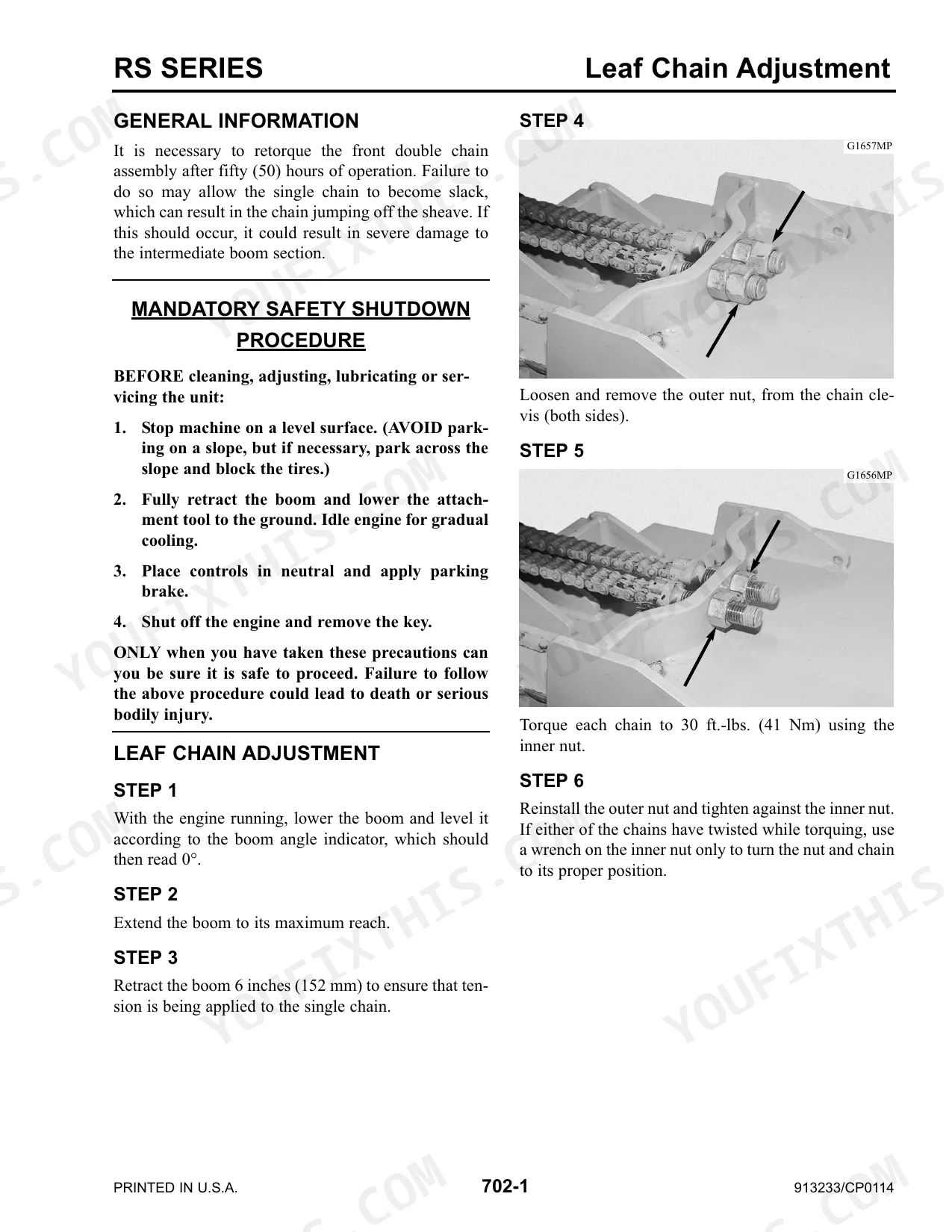
| Boom Cylinders & Assembly (3-Section Boom) | 263-330 | Boom Extend Cylinder, Boom Assembly Removal and Installation, Leaf Chain Adjustment and Maintenance, Inner Boom Removal, Double and Single Chain Roller Bearings, Intermediate Boom, Boom Slide Pad Replacement |
| Boom Assembly & Hose Replacement (4-Section Boom) | 331-400 | Boom Components Overview, Boom Assembly Removal and Installation, 1st and 2nd Intermediate Boom, Inner Boom Removal, Boom Hydraulic Hose and Tube Replacement, Boom Slide Pad Sizes and Maintenance |
| Boom Pad & Chain Replacement (4-Section Boom) | 401-482 | Outer Boom Pad Replacement (Top, Side, Bottom), Inner Boom Top and Bottom Chain, 2nd Intermediate Boom Chain, Outer Boom Chain and Roller Bearing, Boom Chain Adjustment |
| Hood and Cover | 483-498 | Front Hood Removal and Installation, Rear Hood Removal and Installation, Radiator Cover Removal and Installation, Side Door Removal |
Every system also includes mandatory safety shutdown procedure.
Quick Reference Specifications
| Specification | Value | Page |
|---|---|---|
| Wheel nuts torque | 450 ft.-lbs. (610 Nm) | p. 123 |
| Hydraulic filter type | In-tank return type, 10-micron media, replaceable element | p. 27 |
| Hydraulic filter rated flow | 100 gpm (379 L/min) | p. 27 |
| Battery cold cranking amps | 950 cold cranking amps | p. 26 |
| Battery voltage (test value) | 12 to 13 volts | p. 73 |
| SAE "O" Ring Boss (Steel) fittings torque (Minimum) | Varies by dash and fractional size (e.g., -3 (3/16): 8 Ft-Lbs, -24 (1-1/2): 270 Ft-Lbs) | p. 24 |
| SAE "O" Ring Boss (Steel) fittings torque (Maximum) | Varies by dash and fractional size (e.g., -3 (3/16): 10 Ft-Lbs, -24 (1-1/2): 360 Ft-Lbs) | p. 24 |
| Unified National Thread (Grade 2, Dry) torque | Varies by size (e.g., 8-32: 19 lb-in, 1-14: 210 lb-ft) | p. 23 |
| Unified National Thread (Grade 2, Lubed) torque | Varies by size (e.g., 8-32: 14 lb-in, 1-14: 210 lb-ft) | p. 23 |
| Main relief pressure | 3000 psi (207 bar) | p. 143 |
| Steering relief pressure | 2500 psi (172 bar) | p. 143 |
| Unified National Thread Torque (Grade 8, Dry, 1/2-13) | 110 lb-ft | p. 23 |
Gehl RS6–RS12 Series Common Problems This Manual Covers
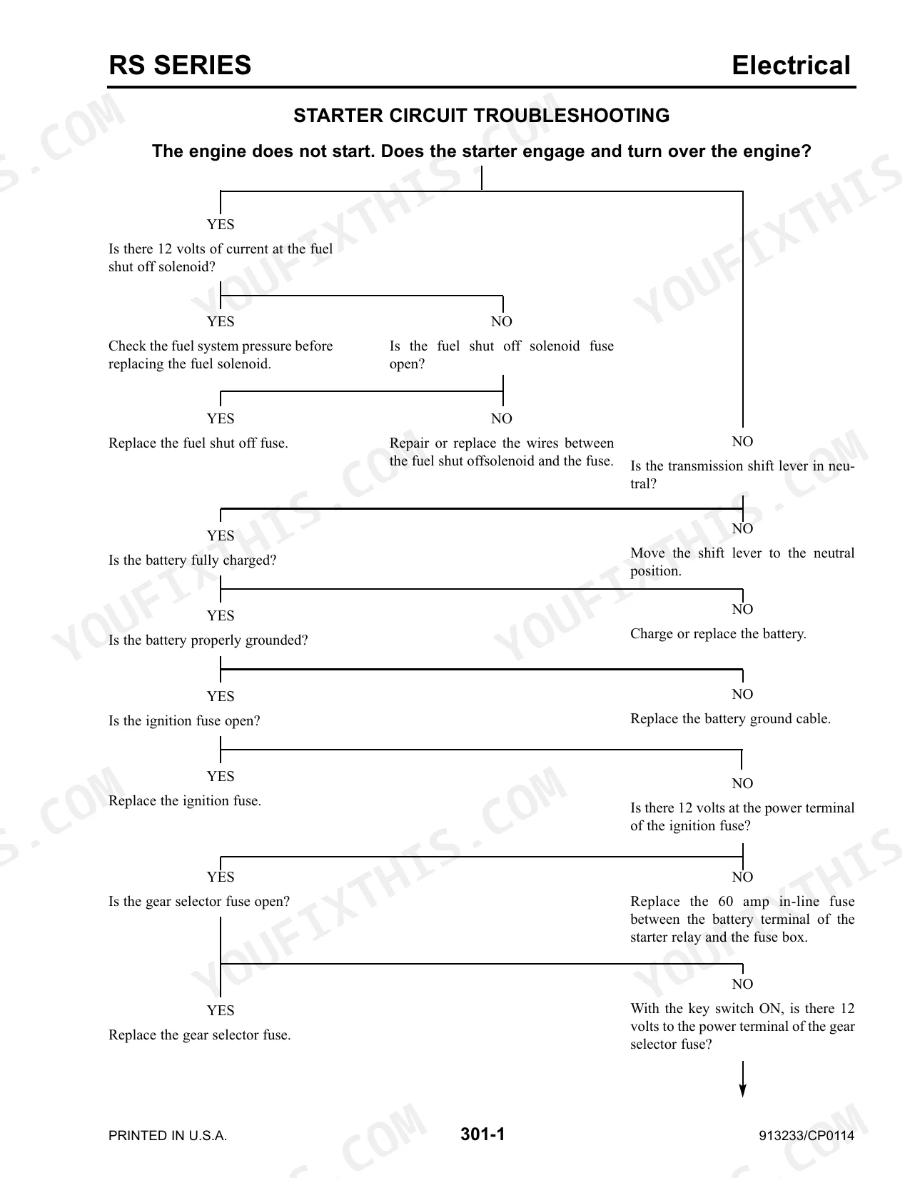
Machine will not start or run
Starting problems and machines that will not run are commonly reported on the RS6-42 family. Work through the starter circuit, key switch, and fuel shut-off solenoid tests before replacing parts.
Manual Section: 301 - Electrical p. 63Will not go into gear
The telehandler will not engage a gear or has drive problems. This usually points to a transmission, shift interlock, or control-system fault that the Transmission section helps isolate.
Manual Section: 501 - Transmission p. 101Boom or hydraulics weak and slow
Boom and attachment functions feel weak, slow, or inconsistent. Low or contaminated hydraulic fluid, pump wear, restricted filters, or pressure loss should be checked against the hydraulic tests.
Manual Section: 601 - Hydraulics p. 139Lift cylinder drifts or will not hold
A lift cylinder that drifts down or will not hold load usually has worn seals or an adjustment out of spec. The Lift Cylinder section covers removal, adjustment, and eccentric pin setting.
Manual Section: 609 - Lift Cylinder p. 249Boom extends or retracts poorly
Uneven boom extend or retract can stem from the extend cylinder or its hydraulic circuit. The Boom Extend Cylinder section covers removal, installation, and relieving hydraulic pressure.
Manual Section: 610 - Boom Extend Cylinder (3-section boom) p. 263Loss of power in cold weather
Owners report less power and hard starting in cold weather. Fuel and engine performance checks in the Engine section help sort cold-weather starting from deeper faults.
Manual Section: 201 - Engine p. 41Frequently Asked Questions
Which telehandlers does this manual cover?
It covers the Gehl RS Series telescopic handlers: the RS6-42, RS8-42, RS8-44, RS10-44, RS10-55, and RS12-42, all with the John Deere 4045T engine.
What is the hydraulic system main relief pressure?
The specifications list a hydraulic system main relief pressure of 3000 psi (207 bar) for all models. p. 27
What is the wheel nut torque?
The service data specifies a wheel nut torque of 450 ft.-lbs. (610 Nm) across the RS Series. p. 123
Are electrical schematics included?
Yes. The Electrical section provides schematics along with starter, park brake, and steering-mode circuit troubleshooting. p. 63
Is this Service Manual a digital download?
This is a 498-page searchable PDF that downloads the moment you check out. Open it on a laptop, tablet, or phone, and carry it straight to the shop floor.
Can I print specific sections of this Service Manual?
Yes. The PDF carries no DRM restrictions, so print any page or section your shop needs. It works with any standard printer.
Are there wiring harness diagrams in this Gehl RS6–RS12 Series manual?
Complete wiring diagrams are included, covering all electrical circuits, harness routing, and connector pinouts for the Gehl RS6–RS12 Series.


Reviews
There are no reviews yet.